 Open Access Article
Creative Commons Attribution 3.0 Unported Licence
Solvothermal water-diethylene glycol synthesis of LiCoPO4 and effects of surface treatments on lithium battery performance†
Min Zhang a,
Nuria Garcia-Araez
 a,
Andrew L. Hector
 *a,
John R. Owena,
Robert G. Palgrave
 b,
Michael G. Palmera and
Samantha Souléa
aSchool of Chemistry, University of Southampton, Highfield, Southampton SO17 1BJ, UK. E-mail: A.L.Hector@soton.ac.uk
bDepartment of Chemistry, University College London, 20 Gordon Street, London WC1H 0AJ, UK
First published on 4th January 2019
Abstract
Olivine-structured LiCoPO4 is prepared via a facile solvothermal synthesis, using various ratios of water/diethylene glycol co-solvent, followed by thermal treatment under Ar, air, 5%H2/N2 or NH3. The diethylene glycol plays an important role in tailoring the particle size of LiCoPO4. It is found that using a ratio of water/diethylene glycol of 1![[thin space (1/6-em)]](https://www.rsc.org/images/entities/char_2009.gif) :
:![[thin space (1/6-em)]](https://www.rsc.org/images/entities/char_2009.gif) 6 (v/v), LiCoPO4 is obtained with a homogenous particle size of ∼150 nm. The bare LiCoPO4 prepared after heating in Ar exhibits high initial discharge capacity of 147 mA h g−1 at 0.1C with capacity retention of 70% after 40 cycles. This is attributed to the enhanced electronic conductivity of LiCoPO4 due to the presence of Co2P after firing under Ar. The effects of carbon, TiN and RuO2 coating are also examined. Contrary to other studies, it is found that the solvothermally synthesised LiCoPO4 samples produced here do not require conductive coatings to achieve good performance.
6 (v/v), LiCoPO4 is obtained with a homogenous particle size of ∼150 nm. The bare LiCoPO4 prepared after heating in Ar exhibits high initial discharge capacity of 147 mA h g−1 at 0.1C with capacity retention of 70% after 40 cycles. This is attributed to the enhanced electronic conductivity of LiCoPO4 due to the presence of Co2P after firing under Ar. The effects of carbon, TiN and RuO2 coating are also examined. Contrary to other studies, it is found that the solvothermally synthesised LiCoPO4 samples produced here do not require conductive coatings to achieve good performance.
Introduction
Development of energy storage and conversion devices is vital to address the increasing energy crisis and ecological concerns in the 21st century.1 Although a variety of renewable energy technologies such as solar cells, fuel cells and biofuels have been developed,2–5 the need for efficient, cheap and reliable storage devices is still pressing when using renewable energies.5 Electrical energy storage like lithium batteries and supercapacitors are effective strategies in making the energy output much cleaner.6–8 As one of the most efficient energy storage devices, lithium-ion batteries (LIBs) are used in portable electronic devices and large-scale electric vehicles9–12 due to their high energy density, high power density and light weight compared with conventional batteries.13–15 The olivine-structured LiMPO4 (M = Fe, Mn, Co, Ni) phases have been intensively investigated as cathode materials for LIBs,15–18 especially LiFePO4 which has been successfully commercialised.19–24 LiCoPO4 has also attracted significant attention due to its high redox potential (4.8 V vs. Li/Li+) and high theoretical capacity (167 mA h g−1), making it a promising future cathode material for high-voltage LIBs.25–30 However, use of LiCoPO4 as a cathode in practical applications has been hindered by its unsatisfactory cycle stability and rate capability, which could be mainly attributed to its low electronic conductivity17,31–36 and poor Li+ ionic conductivity36–41 relating to the one-dimensional ion transport channels,42 as well as to the decomposition of electrolytes under high potentials.43Efforts to overcome the low electronic and ionic conductivity of LiCoPO4 have included: (1) size reduction and morphology control, decreasing the particle size of LiCoPO4 or tailoring its crystal growth orientation along the a–c plane to decrease the diffusion length of lithium ions in the insertion/extraction process;44,45 (2) surface modification (e.g. carbon coating), to enhance the electronic conductivity of the composite electrode by forming a conductive network among the LiCoPO4 particles;42,46 (3) ion doping with cations on either Li or Co sites to enhance the intrinsic electronic/ionic conductivity of LiCoPO4 although the mechanism is still in controversy.29,47 Among these approaches, the combination of size reduction and conductive agent coating (e.g. carbon coating) is regarded as an effective method to enhance the specific capacity and rate capability of LiCoPO4 cathode.48 Reducing the particle size of LiCoPO4 to the nanometer size range can shorten the Li ion transport distance, and thus reduce the time required for Li ion diffusion within the bulk LiCoPO4 material. Carbon coating not only improves the surface electrical conductivity of LiCoPO4 composite, which alleviates electrode polarization, but also provides effective protection from chemical attack by HF produced via electrolyte decomposition at high potentials in LiPF6 based electrolytes.48 Metal oxides30,49–52 and metal nitrides53–56 have been combined with other electrode materials to form structured composites with improved conductivity and stability. TiN and RuO2 are suitable for this purpose as they have good electrical conductivity, and good chemical and thermal stability.53,57
It is important to develop facile, easily scalable and controllable, time and energy saving synthetic routes to produce LiCoPO4 with good electrochemical performance.25 Various synthesis methods such as hydrothermal/solvothermal syntheses,42,44 sol–gel processes58,59 and solid-state reactions60,61 have been proposed. Hydrothermal/solvothermal synthesis is facile and easily scalable, with mild reaction conditions and advantages of producing nanomaterials with controllable particle sizes and morphologies.62 Mixing an organic solvent and water as a co-solvent has been employed in the solvothermal synthesis of LiCoPO4.44,45,62–64 The solvent mixture can be beneficial for effectively tailoring the particle size of LiCoPO4 due to the high viscosity of the organic solvent,62,63 and the water component can promote the dissolution of the reagents.62 However, optimisation of solvothermal conditions to achieve LiCoPO4 cathodes with good specific capacity and cycle performance is still challenging.
Herein, a novel, simple and fast solvothermal approach towards high-performance LiCoPO4 at relatively low temperatures (180 °C) using diethylene glycol (DEG) as a co-solvent is presented, followed by thermal treatment under Ar, air, 5%H2/N2 or NH3. Surface modification of LiCoPO4 with conductive agents like TiN, RuO2 and carbon has been investigated. Unusually in this work the electrochemical performance of samples produced by this method does not require the use of conductive coatings (e.g. carbon) to achieve good electrochemical performance.
Experimental
LiCoPO4 was prepared under solvothermal conditions. We previously reported the phase behaviour during charging of a sample made in this way.65 LiOH (0.359 g, 0.015 mol, Sigma Aldrich) was dissolved/dispersed in 45 ml deionised water/diethylene glycol (H2O/DEG) mixture, then H3PO4 aqueous solution (0.344 cm3, 0.005 mol, 85.3 wt% assay, Fisher Scientific) was added. CoSO4·7H2O (1.405 g, 0.005 mol, ≥ 99% purity, Sigma Aldrich) was dissolved in 25 ml H2O/DEG mixture and added slowly to the LiOH solution with constant stirring, during which time a blue/purple suspension formed. The volume ratio of H2O/DEG was set as pure H2O, 6![[thin space (1/6-em)]](https://www.rsc.org/images/entities/char_2009.gif) :
:![[thin space (1/6-em)]](https://www.rsc.org/images/entities/char_2009.gif) 1, 3
1, 3![[thin space (1/6-em)]](https://www.rsc.org/images/entities/char_2009.gif) :
:![[thin space (1/6-em)]](https://www.rsc.org/images/entities/char_2009.gif) 1, 1
1, 1![[thin space (1/6-em)]](https://www.rsc.org/images/entities/char_2009.gif) :
:![[thin space (1/6-em)]](https://www.rsc.org/images/entities/char_2009.gif) 1, 1
1, 1![[thin space (1/6-em)]](https://www.rsc.org/images/entities/char_2009.gif) :
:![[thin space (1/6-em)]](https://www.rsc.org/images/entities/char_2009.gif) 3, 1
3, 1![[thin space (1/6-em)]](https://www.rsc.org/images/entities/char_2009.gif) :
:![[thin space (1/6-em)]](https://www.rsc.org/images/entities/char_2009.gif) 6 and pure DEG. The precursor solution was heated in a Parr 4748 Teflon-lined autoclave (125 cm3) at 180 °C for 10 h. The precipitate was then washed with deionized water and ethanol, and dried at 80 °C for 5 h under vacuum. The resulting material was heated at 5 °C min−1 to 600 °C and maintained for 3 h under Ar, air, NH3 or 5% H2/N2 to crystallise LiCoPO4.
6 and pure DEG. The precursor solution was heated in a Parr 4748 Teflon-lined autoclave (125 cm3) at 180 °C for 10 h. The precipitate was then washed with deionized water and ethanol, and dried at 80 °C for 5 h under vacuum. The resulting material was heated at 5 °C min−1 to 600 °C and maintained for 3 h under Ar, air, NH3 or 5% H2/N2 to crystallise LiCoPO4.
To obtain carbon or RuO2 coated LiCoPO4 the uncrystallised or pre-fired LiCoPO4, (0.3 g, 1.87 mmol) was manually ground in a pestle and mortar with sucrose (C6H12O6, 0.0375 g, 0.11 mmol, Fisher Scientific) or ruthenium(III) chloride hydrate (RuCl3·xH2O, 0.0246 g, 0.12 mmol, Sigma Aldrich) to obtain a uniform mix that was then heated under Ar as described above. The products were black powders and were ground before further characterisation. TiN modified LiCoPO4 powders were prepared using a propylamine cross-linking sol–gel process53,66–68 under nitrogen using glove box or Schlenk line conditions. Ti(NMe2)4 (0.21 cm3, 0.9 mmol, prepared from TiCl4 and LiNMe2) was dissolved in dry THF (7.5 cm3, distilled from sodium/benzophenone), and added to 0.5 g dry LiCoPO4 powder. nPrNH2 (0.15 cm3, 1.8 mmol, distilled from BaO) was slowly added. The solution gradually changed colour from yellow to red-orange. The suspension was stirred at room temperature for ∼16 h and dried in vacuo to form a sticky powder. This was heated under Ar or NH3 as described above for LiCoPO4 samples.
Powder X-ray diffraction used a Bruker D2 Phaser with CuKα radiation, and data was fitted using the GSAS package.69 Scanning electron microscopy (SEM) used a JEOL JSM-6500F (30 kV). Transmission electron microscopy (TEM) used a FEI Tecnai T12 (120 kV). Brunauer–Emmett–Teller (BET) surface area and pore size distribution measurements via N2 physisorption analysis were carried out with a Micromeritics TriStar II analyser. Electrochemical testing used a Biologics VMP-2 multichannel potentiostat. X-ray photoelectron spectroscopy (XPS) was collected with a two chamber Thermo K-alpha spectrometer with a monochromated Al K-alpha X-ray source (1486.6 eV) in constant analyser energy mode. Sample charging was prevented by use of a dual beam flood gun. X-rays were focused to a 400 μm spot at the sample surface. High resolution core peak spectra were recorded at 50 eV pass energy. Spectra were analysed using Casa XPS software. The binding energy scale was calibrated from the carbon at 285.0 eV. Core peaks were analysed with a nonlinear Shirley-type background.70 The peak positions and areas were optimized using a weighted least-square fitting method with 70% Gaussian and 30% Lorentzian line shapes. Several spectral analyses were applied at different positions for each sample to ensure the results were statistically reliable. Electronic and ionic conductivity was determined from the current–voltage measurement and electrochemical impedance spectroscopy on gold-coated sintered LiCoPO4 disks (11 mm in diameter and ∼0.5 mm in thickness).31,71,72 Current–voltage plots were collected at 20 mV s−1 over the range of −0.3 to +0.3 V (or larger voltage ranges) at room temperature. Electrochemical impedance spectroscopies were collected at 500 mV in the frequency range of 0.1 Hz to 200 kHz at room temperature.
Electrodes for use in lithium half cells were prepared by manually mixing the LiCoPO4 or TiN/carbon/RuO2 coated LiCoPO4 powders (75 wt%) with acetylene black (Shawinigan Black, 20 wt%) and polytetrafluoroethylene (6C–N, DuPont, 5 wt%) in a pestle and mortar. The resulting solid paste was hand rolled (Durston Rolling Mill) into a film of ∼90 μm thickness and cut into circular disks with diameter of 11 mm. The pellet was then dried at 120 °C in vacuo for 12 h to obtain the cathode with a typical mass of ∼0.022 g. Swagelok cells were assembled in an argon-filled glove box with lithium foil (Rockwood Lithium GmbH) anodes and glass microfiber filter (Whatman, GF/F grade) separators soaked in 8 drops (∼0.4 ml) of 1 mol dm−3 LiPF6 in ethylene carbonate/ethylmethyl carbonate (EC![[thin space (1/6-em)]](https://www.rsc.org/images/entities/char_2009.gif) :
:![[thin space (1/6-em)]](https://www.rsc.org/images/entities/char_2009.gif) EMC = 3
EMC = 3![[thin space (1/6-em)]](https://www.rsc.org/images/entities/char_2009.gif) :
:![[thin space (1/6-em)]](https://www.rsc.org/images/entities/char_2009.gif) 7 in weight) electrolyte (BASF, LP57). Galvanostatic testing was carried out at 25 °C at various rates of charge/discharge (e.g. 0.1C for a theoretical specific capacity of 167 mA h g−1 corresponds to a specific current of 16.7 mA g−1) within the voltage range of 3.5–5 V (vs. Li/Li+).
7 in weight) electrolyte (BASF, LP57). Galvanostatic testing was carried out at 25 °C at various rates of charge/discharge (e.g. 0.1C for a theoretical specific capacity of 167 mA h g−1 corresponds to a specific current of 16.7 mA g−1) within the voltage range of 3.5–5 V (vs. Li/Li+).
Results and discussion
LiCoPO4 samples were prepared by a solvothermal method. First, we present a systematic study on the effect of the solvents and heating environment to optimise the solvothermal conditions. Then, LiCoPO4 samples were coated with TiN, carbon or RuO2 with a variety of processing conditions and thicknesses to determine whether the expected conductivity enhancement and increased surface stability improved the electrochemical behaviour of the materials.Effect of solvent on LiCoPO4 morphology in solvothermal synthesis
Uncoated LiCoPO4 samples were produced using H2O/DEG solvent mixtures with various volume ratios, followed by firing at 600 °C in an Ar environment, to determine the effect of solvents on their morphologies. The volume ratio of H2O/DEG in solvothermal synthesis was set as pure H2O, 6![[thin space (1/6-em)]](https://www.rsc.org/images/entities/char_2009.gif) :
:![[thin space (1/6-em)]](https://www.rsc.org/images/entities/char_2009.gif) 1, 3
1, 3![[thin space (1/6-em)]](https://www.rsc.org/images/entities/char_2009.gif) :
:![[thin space (1/6-em)]](https://www.rsc.org/images/entities/char_2009.gif) 1, 1
1, 1![[thin space (1/6-em)]](https://www.rsc.org/images/entities/char_2009.gif) :
:![[thin space (1/6-em)]](https://www.rsc.org/images/entities/char_2009.gif) 1, 1
1, 1![[thin space (1/6-em)]](https://www.rsc.org/images/entities/char_2009.gif) :
:![[thin space (1/6-em)]](https://www.rsc.org/images/entities/char_2009.gif) 3, 1
3, 1![[thin space (1/6-em)]](https://www.rsc.org/images/entities/char_2009.gif) :
:![[thin space (1/6-em)]](https://www.rsc.org/images/entities/char_2009.gif) 6 and pure DEG, which corresponds to samples defined as LCP-H2O(Ar), LCP-6
6 and pure DEG, which corresponds to samples defined as LCP-H2O(Ar), LCP-6![[thin space (1/6-em)]](https://www.rsc.org/images/entities/char_2009.gif) :
:![[thin space (1/6-em)]](https://www.rsc.org/images/entities/char_2009.gif) 1(Ar), LCP-3
1(Ar), LCP-3![[thin space (1/6-em)]](https://www.rsc.org/images/entities/char_2009.gif) :
:![[thin space (1/6-em)]](https://www.rsc.org/images/entities/char_2009.gif) 1(Ar), LCP-1
1(Ar), LCP-1![[thin space (1/6-em)]](https://www.rsc.org/images/entities/char_2009.gif) :
:![[thin space (1/6-em)]](https://www.rsc.org/images/entities/char_2009.gif) 1(Ar), LCP-1
1(Ar), LCP-1![[thin space (1/6-em)]](https://www.rsc.org/images/entities/char_2009.gif) :
:![[thin space (1/6-em)]](https://www.rsc.org/images/entities/char_2009.gif) 3(Ar), LCP-1
3(Ar), LCP-1![[thin space (1/6-em)]](https://www.rsc.org/images/entities/char_2009.gif) :
:![[thin space (1/6-em)]](https://www.rsc.org/images/entities/char_2009.gif) 6(Ar), LCP-DEG(Ar), respectively. The heating temperature affects purity, crystallite/particle size distribution and specific capacity of LiCoPO4.53 Most successful previous studies produce LiCoPO4 samples at 550–700 °C,45,73–75 and in this study samples were fired at 600 °C.
6(Ar), LCP-DEG(Ar), respectively. The heating temperature affects purity, crystallite/particle size distribution and specific capacity of LiCoPO4.53 Most successful previous studies produce LiCoPO4 samples at 550–700 °C,45,73–75 and in this study samples were fired at 600 °C.
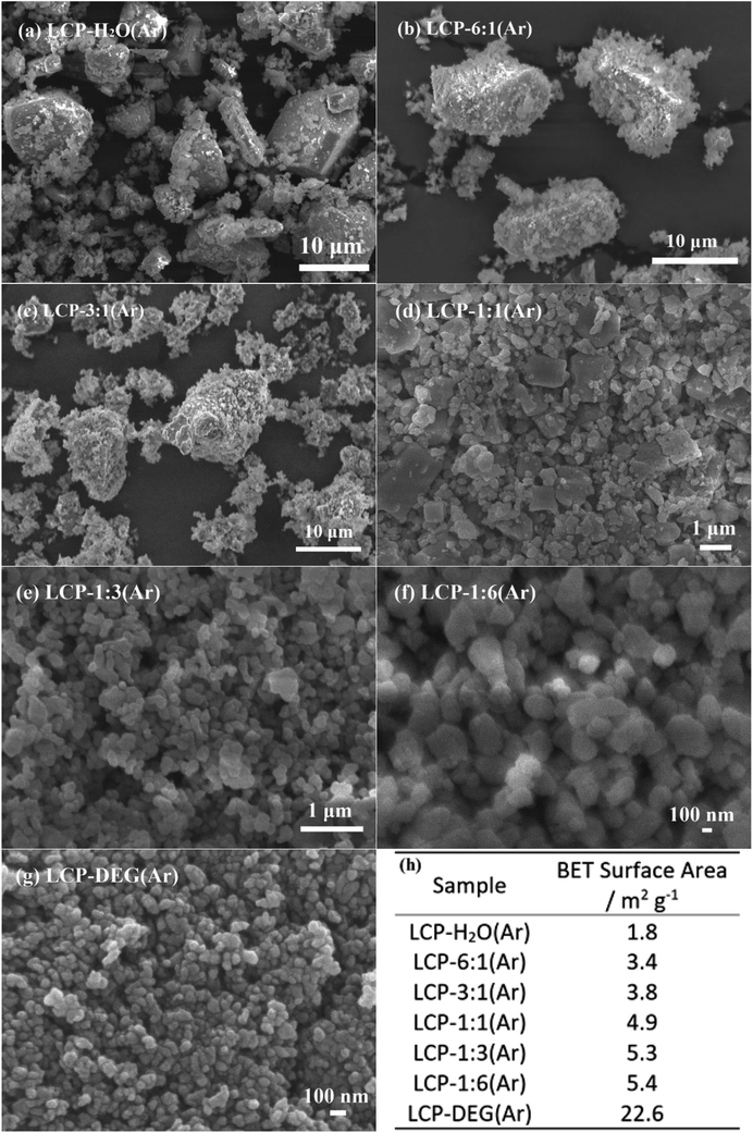
The SEM images (Fig. 1) show the morphologies of LiCoPO4 samples obtained using various ratios of H2O/DEG. The particle size of LiCoPO4 decreased from ∼10 μm to ∼80 nm with increasing DEG content (Fig. 1a–g), and its BET surface area increased from 1.8 to 22.6 m2 g−1 (Fig. 1h). As the ratio of H2O/DEG decreases to less than 1![[thin space (1/6-em)]](https://www.rsc.org/images/entities/char_2009.gif) :
:![[thin space (1/6-em)]](https://www.rsc.org/images/entities/char_2009.gif) 3, the particle size distribution of LiCoPO4 becomes homogeneous (Fig. 1f and g). LiCoPO4 particles readily grow to large sizes in hydrothermal (pure water) synthesis.42,76–78 The pore size distribution of LiCoPO4 samples obtained using various ratios of H2O/DEG were investigated via N2 physisorption analysis (ESI, Fig. S1†). The isotherms of LiCoPO4 samples belong to the type-II, which is reflective of nonporous or macroporous structure. The density functional theory (DFT) pore size distributions calculated from the adsorption curves reveal that the main pore sizes of LiCoPO4 samples are 4–20 nm. These mesopores are created by the interfaces between nonporous LiCoPO4 particles. The control of particle sizes in solvent mixtures has been attributed to the increased viscosity of the solvent mixture when increasing DEG concentration, which can reduce mass transport to growing crystallite surfaces, thus results in decreasing LiCoPO4 particle size.63,79 Also, the solubility of the precursors decreases as the solvent mix becomes less polar, which increases the nucleation rate during the solvothermal process.45 For a given amount of precursor, more nuclei means less matter for each nucleus.45,80 Therefore, larger nucleation rate in solvothermal process could result in smaller LiCoPO4 particle size.
3, the particle size distribution of LiCoPO4 becomes homogeneous (Fig. 1f and g). LiCoPO4 particles readily grow to large sizes in hydrothermal (pure water) synthesis.42,76–78 The pore size distribution of LiCoPO4 samples obtained using various ratios of H2O/DEG were investigated via N2 physisorption analysis (ESI, Fig. S1†). The isotherms of LiCoPO4 samples belong to the type-II, which is reflective of nonporous or macroporous structure. The density functional theory (DFT) pore size distributions calculated from the adsorption curves reveal that the main pore sizes of LiCoPO4 samples are 4–20 nm. These mesopores are created by the interfaces between nonporous LiCoPO4 particles. The control of particle sizes in solvent mixtures has been attributed to the increased viscosity of the solvent mixture when increasing DEG concentration, which can reduce mass transport to growing crystallite surfaces, thus results in decreasing LiCoPO4 particle size.63,79 Also, the solubility of the precursors decreases as the solvent mix becomes less polar, which increases the nucleation rate during the solvothermal process.45 For a given amount of precursor, more nuclei means less matter for each nucleus.45,80 Therefore, larger nucleation rate in solvothermal process could result in smaller LiCoPO4 particle size.
Our previous review on LiCoPO4 inferred that good rate capability is more likely to be achieved by LiCoPO4 with particle size less than 200 nm.25 For example, Wei et al. synthesized carbon coated LiCoPO4 with particle size of 150 nm via a microwave heating method. This nanostructured LiCoPO4 provides a specific capacity of 144 mA h g−1 at 0.1C, with reasonable rate capability of 116, 90 and 71 mA h g−1 at 5, 10 and 20C, respectively.81 In this work, sample LCP-1![[thin space (1/6-em)]](https://www.rsc.org/images/entities/char_2009.gif) :
:![[thin space (1/6-em)]](https://www.rsc.org/images/entities/char_2009.gif) 6(Ar) and LCP-DEG(Ar) showed homogeneous particle size distribution with nanoparticle of less than 200 nm. This small particle size can reduce the length of Li-ion migration paths, and facilitate easier Li-ion transfer in LiCoPO4 crystals, thus enhancing the rate performance of LIBs.45,79,82 However, nanosized LiCoPO4 particles with high surface area can enlarge the electrode/electrolyte interface area, which leads to undesirable electrode/electrolyte by-reactions, thus resulting in a poor cycle stability.20 Hence, sample LCP-1
6(Ar) and LCP-DEG(Ar) showed homogeneous particle size distribution with nanoparticle of less than 200 nm. This small particle size can reduce the length of Li-ion migration paths, and facilitate easier Li-ion transfer in LiCoPO4 crystals, thus enhancing the rate performance of LIBs.45,79,82 However, nanosized LiCoPO4 particles with high surface area can enlarge the electrode/electrolyte interface area, which leads to undesirable electrode/electrolyte by-reactions, thus resulting in a poor cycle stability.20 Hence, sample LCP-1![[thin space (1/6-em)]](https://www.rsc.org/images/entities/char_2009.gif) :
:![[thin space (1/6-em)]](https://www.rsc.org/images/entities/char_2009.gif) 6(Ar) with particle size of ∼150 nm and a relatively small surface area of 5.4 m2 g−1 (compared to LCP-DEG(Ar) with surface area of 22.6 m2 g−1) was chosen for the following studies.
6(Ar) with particle size of ∼150 nm and a relatively small surface area of 5.4 m2 g−1 (compared to LCP-DEG(Ar) with surface area of 22.6 m2 g−1) was chosen for the following studies.
Effect of heating environment on bare LiCoPO4
Ar or air are typical heating environments in thermal treatment to crystallise LiCoPO4, but the intrinsic role and effects of various heating gases on LiCoPO4 has still not been fully ascertained and remains controversial.25 NH3 and 5% H2/N2 are typical heating gases to coat TiN and carbon onto electrode materials.25,48,53 Thus, it is important to evaluate whether heating in NH3 or 5% H2/N2 caused a deterioration in the LiCoPO4 properties. In this section, uncoated LiCoPO4 samples were produced by using the 1![[thin space (1/6-em)]](https://www.rsc.org/images/entities/char_2009.gif) :
:![[thin space (1/6-em)]](https://www.rsc.org/images/entities/char_2009.gif) 6 (v/v) H2O/DEG co-solvent optimised above, and fired at 600 °C in Ar, air, 5% H2/N2 or NH3 to determine the effect of heating environment on their behaviour. Scheme 1 shows the labels used for different samples.
6 (v/v) H2O/DEG co-solvent optimised above, and fired at 600 °C in Ar, air, 5% H2/N2 or NH3 to determine the effect of heating environment on their behaviour. Scheme 1 shows the labels used for different samples.
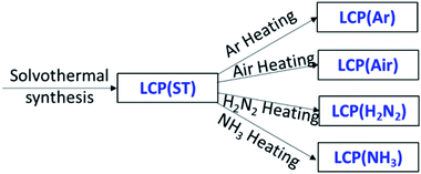 | ||
Scheme 1 Solvothermal synthesis to prepare LiCoPO4, using 1![[thin space (1/6-em)]](https://www.rsc.org/images/entities/char_2009.gif) : :![[thin space (1/6-em)]](https://www.rsc.org/images/entities/char_2009.gif) 6 (v/v) H2O/DEG co-solvent, followed by firing at 600 °C in Ar, air, 5% H2/N2 or NH3. 6 (v/v) H2O/DEG co-solvent, followed by firing at 600 °C in Ar, air, 5% H2/N2 or NH3. | ||
The X-ray diffraction peaks of the resulting LiCoPO4 samples (Fig. 2) were consistent with the standard olivine LiCoPO4 (JCPDS card no. 85–0002, space group Pnma) as expected. Table S1† shows the crystallographic data of LiCoPO4 samples. The Rietveld fits83 to this XRD data (ESI, Fig. S2†) resulted in similar lattice parameters (ESI, Table S1†) to those in the literature for LiCoPO4 indicating that the heating environment did not affect the crystal structure of LiCoPO4.84 The Lorentzian peak broadening in the Rietveld fit indicated average LiCoPO4 crystallite sizes of 119–132 nm. These were consistent with TEM (Fig. 3) and SEM (ESI, Fig. S3†) images of LiCoPO4 fired in Ar, air, 5%H2/N2 and NH3, which showed particle sizes of ∼150 nm. No hydrogen and nitrogen (<0.1 wt%) are detectable according to the microanalysis results (ESI, Table S1†) with a negligible amount of carbon (<0.5 wt%) in the LiCoPO4 samples.
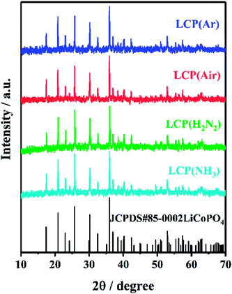 | ||
| Fig. 2 XRD patterns of LiCoPO4 samples heated under Ar, air, 5% H2/N2 and NH3, respectively, at 600 °C (labels explained in Scheme 1). The black stick pattern denotes the literature positions and intensities of LiCoPO4 reflections.85 | ||
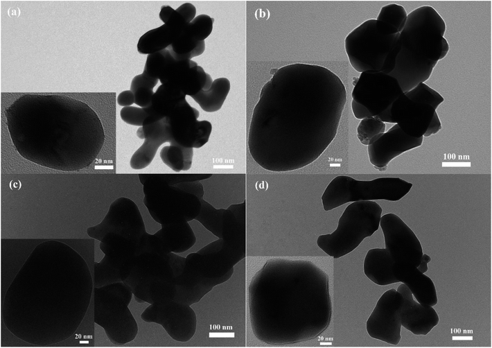 | ||
| Fig. 3 TEM images of (a) LCP(Ar), (b) LCP(air), (c) LCP(H2N2) and (d) LCP(NH3) (scale bar = 100 nm). (Inset) magnified TEM images of single LiCoPO4 particle (scale bar = 20 nm). Sample labels are explained in Scheme 1. | ||
The electrochemical performance of LiCoPO4 samples was assessed by galvanostatic cycling of Li half cells. The initial charge/discharge curves and the variations in discharge capacity and coulombic efficiency  over the first 40 cycles of LiCoPO4 fired in Ar, air, 5% H2/N2 and NH3 are shown in Fig. 4. LCP(Ar), LCP(air), LCP(H2N2) and LCP(NH3) had initial discharge capacities of 147, 130, 139 and 132 mA h g−1, respectively. The capacity of LCP(Ar) decayed gradually with continuous cycling, retaining 102 mA h g−1 after 40 cycles, and 88 mA h g−1 after 57 cycles. The low coulombic efficiency values in the first cycle for these samples are caused by the decomposition of the electrolyte during charge at high potentials.62,86 The coulombic efficiency of LCP(Ar), which improved upon cycling, was 92% in the second cycle and maintains values higher than 95% after five cycles. LiCoPO4 fired in air or in reducing gases had lower initial discharge capacities and lost capacity more rapidly on cycling. A comparison of relevant articles using a hydrothermal/solvothermal methodology in the synthesis of LiCoPO4 olivine phosphate cathodes is presented in Table 1. The obtained specific capacity and cycle stability of uncoated LCP(Ar) in our case is comparable or higher than most previous studies, even though in most of these reports LiCoPO4 has been optimised with conductive coatings (e.g. carbon). Overall the results suggested that Ar firing was the most effective heat treatment to apply for the crystallisation of LiCoPO4, but since air firing is also common in this system,75,87–89 both samples as well as uncrystallised LiCoPO4 were carried forward to test the surface modification of LiCoPO4 with TiN, RuO2 and carbon.
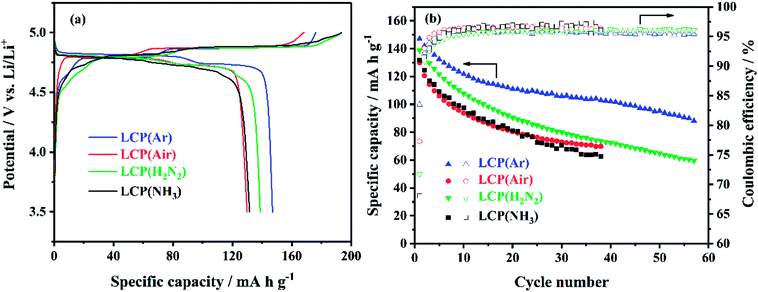 | ||
| Fig. 4 (a) The initial cycle voltage profile vs. specific capacity and (b) specific capacity and coulombic efficiency vs. cycle number of LiCoPO4/Li half cells under galvanostatic cycling between 3.5 and 5 V at 0.1C (sample labels explained in Scheme 1). | ||
| Morphology, particle size | Rate performance, mA h g−1 | Cycle stability | Ref. |
|---|---|---|---|
| Nanoparticles, 150 nm | 147 (0.1C) | 102 mA h g−1 at 0.1C after 40 cycles | This work |
| Irregular nanoparticle | 160 (0.1C), 138 (1C), 120 (2C), 88 (5C) | 138 mA h g−1 at 0.1C after 100 cycles | 73 |
| Hexagonal platelets, 200 × 100 × 50 nm to 1.2 × 1.2 × 0.5 μm | 136 (0.1C), 125 (0.2C), 115 (0.5C), 105 (1C), 95 (2C) | 108 mA h g−1 at 0.5C after 15 cycles | 63 |
| Square, rhombic and hexagonal platelets, 600–800 × 400–600 × 100–150 nm to 9 × 7 × 3 μm | 141 (0.1C), 135 (0.2C), 130 (0.5C), 123 (1C), 112 (2C) | 125 mA h g−1 at 0.5C after 15 cycles | 44 |
| Spherical or oblong spheroid, 50–250 nm | 145 (0.1C) | 74 mA h g−1 at 0.1C after 20 cycles | 90 |
| Irregular particles, 390 nm to 2.8 μm | 135 (0.1C), 132 (0.5C), 125 (1C), 117 (2C), 101 (5C) | 70 mA h g−1 0.1C after 30 cycles | 42 |
| Irregular particles, 200 nm to 1 μm | 155 (0.1C), 129 (1C), 98 (5C), 70 (10C), 51 (20C) | 141 mA h g−1 at 0.1C after 80 cycles | 74 |
| Particles, 100–500 nm | 97 (0.1C) | 82 mA h g−1 at 0.1C after 20 cycles | 85 |
| Particles, 500 nm to 10 μm | 124 (0.1C), 111 (0.5C), 100 (1C), 85 (2C), 51 (5C) | 103 mA h g−1 at 0.1C after 100 cycles | 45 |
| Hexagonal platelets, 400–600 × 700–800 × 100–220 nm | 137 (0.1C), 114 (0.5C), 97 (2C) | 78 mA h g−1 at 0.5C after 100 cycles | 62 |
| Hexagonal platelets, thickness < 200 nm | 120 (0.1C), 85 (0.5C), 75 (1C) | 90 mA h g−1 at 0.1C after 10 cycles | 64 |
| Flower-like, 5–10 μm (compose of plate-like, 1–2 μm × 200 nm) | 107 (0.05C), 60 (2C) | 30 mA h g−1 at 0.05C after 20 cycles | 78 |
| Hexagonal/octagonal platelet, thickness of 50–100 nm | 95 (0.1C), 76 (0.5C) | 75 mA h g−1 at 0.1C after 10 cycles | 91 and 92 |
| Nanoparticles agglomeration, 2–3 μm | 105 (0.2C) | 95 mA h g−1 at 0.2C after 30 cycles | 93 |
| Hedgehog-like, 5–8 μm (compose of nanorods, 40 nm × 1 μm) | 136 (0.1C), 85 (5C) | 124 mA h g−1 at 0.1C after 50 cycles | 94 |
| Rod, 300–700 nm × 5 μm | 65 (0.1C) | 50 mA h g−1 at 0.1C after 10 cycles | 77 |
| Cubes, 1.2–1.5 μm × 250 nm | 52 (0.1C) | 15 mA h g−1 at 0.1C after 25 cycles | 76 |
Synthesis, microstructure and electrochemistry of LiCoPO4 modified with TiN, RuO2 or C
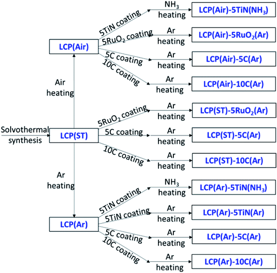
Three kinds of LiCoPO4 were chosen for coating, the uncrystallised LiCoPO4 directly after solvothermal synthesis, with the advantage of a single heating step, and the LiCoPO4 already crystallised in Ar or air (Scheme 2). RuO2 and C coatings were prepared by manually grinding the precursors (RuCl3·xH2O or sucrose) together with LiCoPO4, then firing under Ar.45,57 This solid-state process proved to be an easy and effective method to achieve carbon coatings on LiCoPO4.25,45 TiN coating used a propylamine-crosslinked sol–gel method, then firing under Ar or NH3. This sol–gel process has been shown to be effective to achieve TiN coatings onto LIB cathode materials according to our previous research.53 Scheme 2 summarises these approaches.All the X-ray diffraction peaks of the resulting TiN, RuO2 and C coated LiCoPO4 samples (Fig. 5) can be indexed to the standard olivine LiCoPO4 structure. The characteristic peaks of TiN and RuO2 were not detectable in coated LiCoPO4 composites due to their low concentrations. Carbon coatings on battery materials are typically amorphous when heating at around 600 °C,48,61,81 and also were not visible in the diffraction data. Fig. S4–S6† show the Rietveld fits to the XRD data, which yielded typical LiCoPO4 lattice parameters (ESI, Tables S2–S4†),84 suggesting that the coating processes did not affect the crystal structure of LiCoPO4.
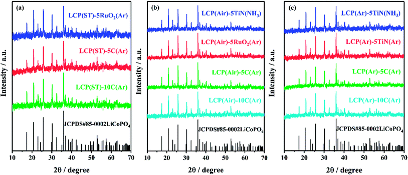 | ||
| Fig. 5 XRD patterns of uncrystallised LiCoPO4 directly after solvothermal synthesis (left), and LiCoPO4 heated under air (centre) or Ar (right) at 600 °C, then modified with TiN, RuO2 and carbon, respectively (labels explained in Scheme 2). The black stick pattern denotes the literature positions and intensities of LiCoPO4 reflections.85 | ||
Fig. 6 shows the initial charge/discharge curves at 0.1C and the cycle stability of electrodes produced from the coated materials. Carbon is the most commonly used battery material coating, but RuO2 has been used to coat electroactive materials to offer a high electronic conductivity and quick Li permeation.95–98 Due to its good electrical conductivity, chemical stability and thermal stability, TiN has been combined with other electrode materials to form structured composites with improved conductivity and stability.53,55,56
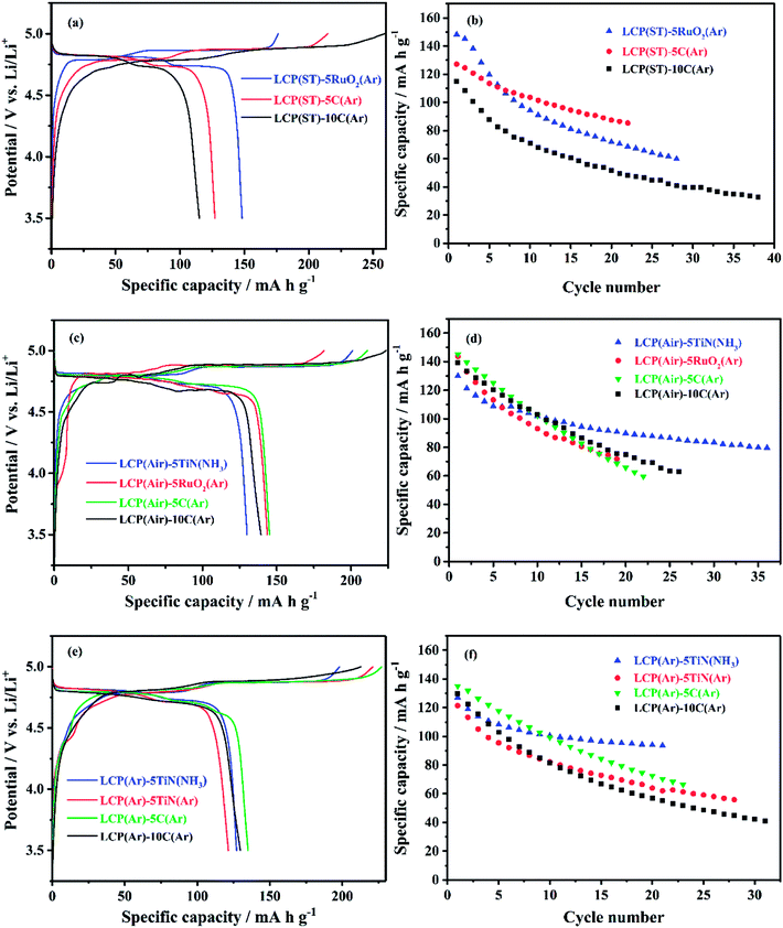 | ||
| Fig. 6 (a), (c) and (e) The initial cycle voltage profile vs. specific capacity, and (b), (d) and (f) specific capacity vs. cycle number of TiN, RuO2 or C coated LiCoPO4 samples made into Li half cells, under galvanostatic cycling between 3.5 and 5 V at 0.1C (sample labels explained in Scheme 2, with the percentage of TiN, RuO2 or C in the composite written after the hyphen). | ||
RuO2 coating of the unfired LiCoPO4 (Fig. 6a and b) resulted in a higher initial discharge capacity of 148 mA h g−1 as expected due to the utility of RuO2 in generating very effective mixed conducting heterogeneous electrodes.57 However, its capacity drops quickly in subsequent cycles. The carbon coated samples had lower capacities than their uncoated counterparts, and the drop in capacity when C content was increased from 5% to 10% suggests that the thicker carbon coating hindered lithium diffusion.
Air fired LiCoPO4 samples coated with TiN, RuO2, 5 wt% C or 10 wt% C (Fig. 6c and d) had initial discharge capacities of 130, 144, 145 and 139 mA h g−1, respectively. The TiN coated sample retained a fairly large fraction of the initial capacity during continuous cycling.53 However, the cycle stability was quite similar to the uncoated LCP(air) (Fig. 4), so the coatings did not significantly improve the electrochemical performance of LiCoPO4. Notably cycle stability was less good with RuO2 or C coatings than with uncoated material.
A similar position was observed with the Ar-fired LiCoPO4 (Fig. 6e and f). The capacities of the C or TiN coated samples dropped to around 100 mA h g−1 over 10 cycles, a poorer cycle stability than that of the uncoated LCP(Ar), which retained 102 mA h g−1 after 40 cycles (Fig. 4). The coatings did not deliver the expected improvement in electrochemical performance of LiCoPO4. However, the purpose of the conductive agent coating was to create a conductive network among the LiCoPO4 particles to improve the conductivity of the composites. These results show that, using these optimised solvothermal conditions, the conductivity of the bare LCP(Ar) sample is good enough to provide competitive specific capacity and cycle stability.
Further investigation of LiCoPO4 fired in Ar and air
The electronic and ionic conductivity of LiCoPO4 powders fired in Ar and air was evaluated with current–voltage measurements and electrochemical impedance spectroscopy. LiCoPO4 samples were pressed, sintered and gold-coated to produce self-standing LiCoPO4 disks, which were dry contacted with two silver paste electrodes. The linear current–voltage plots (Fig. 7) showed that the LCP(Ar) pellet behaves as a resistor and the current–voltage relationship is given by Ohm's law: V = IR. Hence, the resistance of the LiCoPO4 samples can be estimated as being equal to the inverse of the slope of the current–voltage plot. The conductivity of the samples is given by where σ is the conductivity, l is the thickness of the LiCoPO4 pellets (0.48 mm for LCP(Ar) and 0.64 mm for LCP(air) sample), A is the area of the LiCoPO4 pellets (95 mm2), and R is the resistance (42.2 Ω for LCP(Ar) and 1.7 × 10⁷ Ω for LCP(air) sample). The conductivities of LCP(Ar) and LCP(air) are calculated to be ∼10−3 S cm−1 and ∼10−9 S cm−1, respectively. Current–voltage plots with larger voltage ranges are shown in Fig. S7,† and they are in agreement with those in Fig. 7.
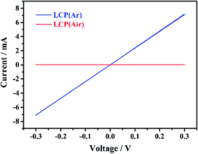 | ||
| Fig. 7 Current–voltage plots (3 cycles each) for LiCoPO4 samples fired in Ar and air, respectively, cycling at scanning rate of 20 mV s−1, showing the ohmic behaviour of the samples (labels explained in Scheme 1). | ||
These conductivity results can be confirmed by electrochemical impedance spectroscopy measurements of the gold-coated pressed LiCoPO4 pellets, as presented in Fig. S8.† The impedance of the LCP(Ar) sample shows purely resistor behaviour (ESI, Fig. S8a†). This is in agreement with the fact that this sample has reasonably high electronic conductivity of ∼10−3 S cm−1, estimated from the value of the resistance and taking into account the dimension of the pellet. On the other hand, the LCP(air) sample shows much higher values of impedance (ESI, Fig. S8b†). This is ascribed to the fact that this sample has much higher electronic resistance, thus it behaves as a resistor coupled to a capacitor (or a constant phase element) in parallel. In addition, the surface of the pellet cannot be polished prior to gold coating (due to the fragility of the pellet), thus the LiCoPO4–gold interphase behaves as a Warburg element, rather than a capacitor or a constant phase element. By fitting the data to the equivalent circuit shown in Fig. S8b,† the electronic conductivity of the LCP(air) sample is estimated to ∼10−9 S cm−1. This is in agreement with the estimation of the total conductivity of the samples by using current–voltage measurements, and the dramatic difference in conductivity between these two samples explains the fact that the sample fired in Ar showed better specific capacity and cycling performance.
Wolfenstine et al. investigated the effect of added carbon on the electronic conductivity and specific capacity of LiCoPO4, and found that the added carbon was partly consumed to reduce the LiCoPO4 surface layers to Co2P during heating under Ar atmosphere.33,34 The formation of highly conductive (∼10−1 S cm−1) Co2P phase in LiCoPO4 cathode led to improved electrochemical performance. As the amount of the Co2P phase increased to 4 wt%, the electronic conductivity increased to ∼10−4 S cm−1 with a maximum discharge capacity of ∼120 mA h g−1 obtained. However, for LiCoPO4 cathodes with higher concentrations of Co2P, the capacities dropped rapidly due to the electrochemically inert Co2P phase, which improves the electronic conductivity but tends to hinder the Li+ insertion/extraction. Similar phenomena were also observed by Xu99 and Indris et al.88 Ma et al. demonstrated that the presence of Co2P can accelerate the electrolyte decomposition at high voltage in the charge process for LiCoPO4 due to the catalytic property of Co2P.100 Dimesso et al. suggested that the formation of Co2P occurs due to reduction reactions at the grain boundaries of the LiCoPO4 crystalline phase during annealing at high temperatures.101–107 Brutti et al. synthesized LiCoPO4 via a solvothermal synthesis followed by heating under Ar atmosphere. It was found that the heating promotes Co2P precipitation on the LiCoPO4 particles surface together with loss of organic by-products formed in the solvothermal synthesis.108 Nallathamby et al. confirmed that the presence of Co2P as a second phase enhanced the conductivity and electrochemical performance of LiCoPO4. It was found that the Co2P is achievable only in an inert atmosphere. The LiCoPO4 cathode showed a discharge capacity of 123 mA h g−1 at 0.1C with capacity retention of 89% after 30 cycles, and rate capability of 81 mA h g−1 at 5C.61
Based on the discussion above, the better conductivity of LiCoPO4 heated in Ar was considered likely to be due to the presence of Co2P on the surface on LiCoPO4. X-ray photoelectron spectroscopy (XPS) of LiCoPO4 samples fired under Ar and air is shown in Fig. 8. These two samples had similar Li 1s and C 1s spectra (ESI, Fig. S9†). Particularly, for the LiCoPO4 fired under Ar, the Li 1s signal located at 55.7 eV is well in accordance with the value reported for LiCoPO4.61 The C 1s spectrum consists of three peaks, with the main component at 285.0 eV corresponding to C–C, and the other two peaks observed at 287.1 eV and 289.0 eV attributed to C–O and O![[double bond, length as m-dash]](https://www.rsc.org/images/entities/char_e001.gif) C–O environments of carbon.109 Fig. 8 shows clear differences between the chemical environments present in the P 2p and O 1s spectra of these samples. For the LiCoPO4 fired under Ar, the O 1s spectrum with a binding energy of 531.6 eV is in agreement with the air-fired sample and with the (PO4)3− environment in LiCoPO4,61 but an additional weak peak at 529.1 eV demonstrates the presence of a small amount of metal oxide (e.g. Li2O with binding energy of 528.6 eV for O 1s spectrum).110–112 The P 2p spectrum (2p3/2 and 2p1/2 doublet) shows the main component at 133.5–134.4 eV in accordance with LiCoPO4,91 and a doublet at lower binding energy (130.9–131.8 eV) that corresponds to Co2P.113 A small shift in binding energy of P 2p in Co2P (expected at around 129 eV) is likely to be due to a differential charging effect resulting from the different electrical conductivities at the surfaces of LiCoPO4 and Co2P.113–115 Co2P formation in Ar fired LiCoPO4 is attributed to the carbon-containing organic solvent (DEG) chosen for the synthesis, which can decompose at high temperature and the resulting carbon can cause carbothermal reduction to reduce the LiCoPO4 surface layers to Co2P during heating under inert atmosphere.33,34,61,101,105,108 This process also explains the relatively low carbon content measured in these samples by microanalysis. The Co 2p spectra are not fitted due to the complexity of the 2p spectra resulting from peak asymmetries, complex doublet splitting, shake-up and plasmon loss structure, and uncertain, overlapping binding energies.116 For the LiCoPO4 fired under Ar, the 2p3/2 and 2p1/2 doublet in the Co 2p spectrum has binding energy values of 781.5 and 797.6 eV, respectively. In LCP(air) these peaks are observed at 782.1 eV and 798.1 eV (2p3/2 and 2p1/2). The shift to lower binding energy can be attributed to the presence of Co2P in LCP(Ar).113 The difference of binding energy between Co 2p3/2 and its satellite peak is in agreement with the Co2+ environment in LiCoPO4.91,116 For the LiCoPO4 fired under air, a new chemical environment corresponding to P2O5 is identified with additional peaks in the P 2p (135.3–136.1 eV) and O 1s (533.3 eV) spectra.117,118
C–O environments of carbon.109 Fig. 8 shows clear differences between the chemical environments present in the P 2p and O 1s spectra of these samples. For the LiCoPO4 fired under Ar, the O 1s spectrum with a binding energy of 531.6 eV is in agreement with the air-fired sample and with the (PO4)3− environment in LiCoPO4,61 but an additional weak peak at 529.1 eV demonstrates the presence of a small amount of metal oxide (e.g. Li2O with binding energy of 528.6 eV for O 1s spectrum).110–112 The P 2p spectrum (2p3/2 and 2p1/2 doublet) shows the main component at 133.5–134.4 eV in accordance with LiCoPO4,91 and a doublet at lower binding energy (130.9–131.8 eV) that corresponds to Co2P.113 A small shift in binding energy of P 2p in Co2P (expected at around 129 eV) is likely to be due to a differential charging effect resulting from the different electrical conductivities at the surfaces of LiCoPO4 and Co2P.113–115 Co2P formation in Ar fired LiCoPO4 is attributed to the carbon-containing organic solvent (DEG) chosen for the synthesis, which can decompose at high temperature and the resulting carbon can cause carbothermal reduction to reduce the LiCoPO4 surface layers to Co2P during heating under inert atmosphere.33,34,61,101,105,108 This process also explains the relatively low carbon content measured in these samples by microanalysis. The Co 2p spectra are not fitted due to the complexity of the 2p spectra resulting from peak asymmetries, complex doublet splitting, shake-up and plasmon loss structure, and uncertain, overlapping binding energies.116 For the LiCoPO4 fired under Ar, the 2p3/2 and 2p1/2 doublet in the Co 2p spectrum has binding energy values of 781.5 and 797.6 eV, respectively. In LCP(air) these peaks are observed at 782.1 eV and 798.1 eV (2p3/2 and 2p1/2). The shift to lower binding energy can be attributed to the presence of Co2P in LCP(Ar).113 The difference of binding energy between Co 2p3/2 and its satellite peak is in agreement with the Co2+ environment in LiCoPO4.91,116 For the LiCoPO4 fired under air, a new chemical environment corresponding to P2O5 is identified with additional peaks in the P 2p (135.3–136.1 eV) and O 1s (533.3 eV) spectra.117,118
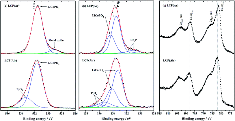 | ||
| Fig. 8 P 2p, O 1s and Co 2p XPS spectra of LiCoPO4 samples fired in Ar and air, respectively (labels explained in Scheme 1). The data points and enveloped fitting plot are overlaid in black dots and a red line, respectively. The fitting peaks and background are shown in blue and green, respectively. | ||
The best specific capacity (147 mA h g−1) and cycling performance of LiCoPO4 shown in Fig. 4, achieved by heating in Ar, can be attributed the good electronic conductivity (∼10−3 S cm−1) of LiCoPO4 due to the presence of Co2P after firing under Ar. Also, the nanosized LiCoPO4 obtained from DEG promoted solvothermal synthesis provides short Li-ion migration paths, and facilitates easier Li-ion transfer within the material. The LiCoPO4 fired in air showed relatively low initial specific capacity of 130 mA h g−1. This could be attributed to the poor electric conductivity of ∼10−9 S cm−1 (Fig. 7 and S8†) as there is no evidence of the presence of Co2P in this sample.
Conclusions
A facile solvothermal synthesis to prepare olivine-structured LiCoPO4 for high-voltage cathodes in LIBs has been developed, using various ratios of water/diethylene glycol as solvent, followed by thermal treatment under Ar, air, 5% H2 + N2 or NH3. The diethylene glycol plays an important role in tailoring the particle size of LiCoPO4. It is found that using a ratio of water/diethylene glycol of 1![[thin space (1/6-em)]](https://www.rsc.org/images/entities/char_2009.gif) :
:![[thin space (1/6-em)]](https://www.rsc.org/images/entities/char_2009.gif) 6 (v/v), LiCoPO4 is obtained with a homogenous particle size of ∼150 nm. The LiCoPO4 prepared after heating in Ar exhibits high initial discharge capacity of 147 mA h g−1 at 0.1C with capacity retention of 70% after 40 cycles. This is attributed to the enhanced electronic conductivity of LiCoPO4 due to the presence of Co2P after firing under Ar. The specific capacity and cycle stability of carbon, TiN and RuO2 coated LiCoPO4 were also examined, but did not improve the performance of the material. Hence, under our solvothermal synthesis conditions, LiCoPO4 with good discharge capacity and cycle stability, without need for separate conductivity coatings, were produced.
6 (v/v), LiCoPO4 is obtained with a homogenous particle size of ∼150 nm. The LiCoPO4 prepared after heating in Ar exhibits high initial discharge capacity of 147 mA h g−1 at 0.1C with capacity retention of 70% after 40 cycles. This is attributed to the enhanced electronic conductivity of LiCoPO4 due to the presence of Co2P after firing under Ar. The specific capacity and cycle stability of carbon, TiN and RuO2 coated LiCoPO4 were also examined, but did not improve the performance of the material. Hence, under our solvothermal synthesis conditions, LiCoPO4 with good discharge capacity and cycle stability, without need for separate conductivity coatings, were produced.
Conflicts of interest
There are no conflicts of interest to declare.Acknowledgements
MZ thanks the China Scholarship Council (CSC) and the University of Southampton for support. NGA thanks the EPSRC for an early career fellowship (EP/N024303/1) and SS is supported by EPSRC under EP/N035437/1. All data supporting this study are openly available from the University of Southampton repository at https://doi.org/10.5258/SOTON/D0767.Notes and references
- P. Poizot and F. Dolhem, Energy Environ. Sci., 2011, 4, 2003–2019 RSC.
- J. P. Correa-Baena, M. Saliba, T. Buonassisi, M. Grätzel, A. Abate, W. Tress and A. Hagfeldt, Science, 2017, 358, 739–744 CrossRef CAS PubMed.
- Z. M. Bhat, R. Thimmappa, M. C. Devendrachari, A. R. Kottaichamy, S. P. Shafi, S. Varhade, M. Gautam and M. O. Thotiyl, J. Phys. Chem. Lett., 2018, 9, 388–392 CrossRef PubMed.
- M. Guo, W. Song and J. Buhain, Renewable Sustainable Energy Rev., 2015, 42, 712–725 CrossRef CAS.
- L. Dimesso, C. Forster, W. Jaegermann, J. P. Khanderi, H. Tempel, A. Popp, J. Engstler, J. J. Schneider, A. Sarapulova, D. Mikhailova, L. A. Schmitt, S. Oswald and H. Ehrenberg, Chem. Soc. Rev., 2012, 41, 5068–5080 RSC.
- N. Mahne, S. E. Renfrew, B. D. McCloskey and S. A. Freunberger, Angew. Chem., Int. Ed., 2018, 57, 5529–5533 CrossRef CAS PubMed.
- E. Mourad, L. Coustan, P. Lannelongue, D. Zigah, A. Mehdi, A. Vioux, S. A. Freunberger, F. Favier and O. Fontaine, Nat. Mater., 2017, 16, 446–453 CrossRef CAS PubMed.
- N. C. Dargily, R. Thimmappa, Z. M. Bhat, M. C. Devendrachari, A. R. Kottaichamy, M. Gautam, S. P. Shafi and M. O. Thotiyl, J. Phys. Chem. Lett., 2018, 9, 2492–2497 CrossRef PubMed.
- N. Dupre, M. Cuisinier, J. F. Martin and D. Guyomard, ChemPhysChem, 2014, 15, 1922–1938 CrossRef CAS PubMed.
- F. Yu, L. Zhang, Y. Li, Y. An, M. Zhu and B. Dai, RSC Adv., 2014, 4, 54576–54602 RSC.
- S. Deng, H. Wang, H. Liu, J. Liu and H. Yan, Nano-Micro Lett., 2014, 6, 209–226 CrossRef.
- L.-X. Yuan, Z.-H. Wang, W.-X. Zhang, X.-L. Hu, J.-T. Chen, Y.-H. Huang and J. B. Goodenough, Energy Environ. Sci., 2011, 4, 269–284 RSC.
- C. Gong, Z. Xue, S. Wen, Y. Ye and X. Xie, J. Power Sources, 2016, 318, 93–112 CrossRef CAS.
- T. V. S. L. Satyavani, A. Srinivas Kumar and P. S. V. Subba Rao, Engineering Science and Technology, an International Journal, 2016, 19, 178–188 CrossRef.
- H. Wu, Q. Liu and S. Guo, Nano-Micro Lett., 2014, 6, 316–326 CrossRef PubMed.
- A. Eftekhari, J. Power Sources, 2017, 343, 395–411 CrossRef CAS.
- J. Wang and X. Sun, Energy Environ. Sci., 2012, 5, 5163–5185 RSC.
- Y. Wang, P. He and H. Zhou, Energy Environ. Sci., 2011, 4, 805–817 RSC.
- Z. Yang, Y. Dai, S. Wang and J. Yu, J. Mater. Chem. A, 2016, 4, 18210–18222 RSC.
- J. Wang and X. Sun, Energy Environ. Sci., 2015, 8, 1110–1138 RSC.
- Z. Bi, X. Zhang, W. He, D. Min and W. Zhang, RSC Adv., 2013, 3, 19744–19751 RSC.
- W.-J. Zhang, J. Power Sources, 2011, 196, 2962–2970 CrossRef CAS.
- D. Jugović and D. Uskoković, J. Power Sources, 2009, 190, 538–544 CrossRef.
- G. K. Singh, G. Ceder and M. Z. Bazant, Electrochim. Acta, 2008, 53, 7599–7613 CrossRef CAS.
- M. Zhang, N. Garcia-Araez and A. L. Hector, J. Mater. Chem. A, 2018, 6, 14483–14517 RSC.
- A. Mauger, C. M. Julien, M. Armand, J. B. Goodenough and K. Zaghib, Curr. Opin. Electrochem., 2017, 6, 63–69 CrossRef CAS.
- J. Ludwig and T. Nilges, J. Power Sources, 2018, 382, 101–115 CrossRef CAS.
- M. Hu, X. L. Pang and Z. Zhou, J. Power Sources, 2013, 237, 229–242 CrossRef CAS.
- L. Fang, H. J. Zhang, Y. Zhang, L. Liu and Y. Wang, J. Power Sources, 2016, 312, 101–108 CrossRef CAS.
- A. Örnek, J. Power Sources, 2017, 356, 1–11 CrossRef.
- J. Wolfenstine, U. Lee, B. Poese and J. L. Allen, J. Power Sources, 2005, 144, 226–230 CrossRef CAS.
- K. Tadanaga, F. Mizuno, A. Hayashi, T. Minami and M. Tatsumisago, Electrochemistry, 2003, 71, 1192–1195 CAS.
- J. Wolfenstine, J. Power Sources, 2006, 158, 1431–1435 CrossRef CAS.
- J. Wolfenstine, J. Read and J. L. Allen, J. Power Sources, 2007, 163, 1070–1073 CrossRef CAS.
- J. L. Allen, T. Thompson, J. Sakamoto, C. R. Becker, T. R. Jow and J. Wolfenstine, J. Power Sources, 2014, 254, 204–208 CrossRef CAS.
- K. Rissouli, K. Benkhouja, J. Ramos-Barrado and C. Julien, Mater. Sci. Eng., B, 2003, 98, 185–189 CrossRef.
- M. Prabu, S. Selvasekarapandian, M. V. Reddy and B. V. R. Chowdari, J. Solid State Electrochem., 2012, 16, 1833–1839 CrossRef CAS.
- J. Xie, N. Imanishi, T. Zhang, A. Hirano, Y. Takeda and Y. Yamamoto, J. Power Sources, 2009, 192, 689–692 CrossRef CAS.
- M. Prabu, S. Selvasekarapandian, A. R. Kulkarni, S. Karthikeyan, G. Hirankumar and C. Sanjeeviraja, Solid State Sci., 2011, 13, 1714–1718 CrossRef CAS.
- D. Shanmukaraj and R. Murugan, Ionics, 2004, 10, 88–92 CrossRef CAS.
- D. Morgan, A. Van der Ven and G. Ceder, Electrochem. Solid-State Lett., 2004, 7, A30–A32 CrossRef CAS.
- Y. Maeyoshi, S. Miyamoto, Y. Noda, H. Munakata and K. Kanamura, J. Power Sources, 2017, 337, 92–99 CrossRef CAS.
- Y. H. Ikuhara, X. Gao, C. A. J. Fisher, A. Kuwabara, H. Moriwake, K. Kohama, H. Iba and Y. Ikuhara, J. Mater. Chem. A, 2017, 5, 9329–9338 RSC.
- J. Ludwig, C. Marino, D. Haering, C. Stinner, H. A. Gasteiger and T. Nilges, J. Power Sources, 2017, 342, 214–223 CrossRef CAS.
- B. R. Wu, H. L. Xu, D. B. Mu, L. L. Shi, B. Jiang, L. Gai, L. Wang, Q. Liu, L. B. Ben and F. Wu, J. Power Sources, 2016, 304, 181–188 CrossRef CAS.
- N. Laszczynski, A. Birrozzi, K. Maranski, M. Copley, M. E. Schuster and S. Passerini, J. Mater. Chem. A, 2016, 4, 17121–17128 RSC.
- S. Brutti, J. Manzi, D. Meggiolaro, F. M. Vitucci, F. Trequattrini, A. Paolone and O. Palumbo, J. Mater. Chem. A, 2017, 5, 14020–14030 RSC.
- Y. Liu, M. Zhang, Y. Li, Y. Hu, M. Zhu, H. Jin and W. Li, Electrochim. Acta, 2015, 176, 689–693 CrossRef CAS.
- B. León, C. P. Vicente, J. Tirado, P. Biensan and C. Tessier, J. Electrochem. Soc., 2008, 155, A211–A216 CrossRef.
- H. Liu, G. X. Wang, D. Wexler, J. Z. Wang and H. K. Liu, Electrochem. Commun., 2008, 10, 165–169 CrossRef CAS.
- Y. Liu, C. Mi, C. Yuan and X. Zhang, J. Electroanal. Chem., 2009, 628, 73–80 CrossRef CAS.
- Y.-D. Li, S.-X. Zhao, C.-W. Nan and B.-H. Li, J. Alloys Compd., 2011, 509, 957–960 CrossRef CAS.
- M. Zhang, N. Garcia-Araez, A. L. Hector and J. R. Owen, J. Mater. Chem. A, 2017, 5, 2251–2260 RSC.
- S. Dong, X. Chen, L. Gu, X. Zhou, L. Li, Z. Liu, P. Han, H. Xu, J. Yao, H. Wang, X. Zhang, C. Shang, G. Cui and L. Chen, Energy Environ. Sci., 2011, 4, 3502–3508 RSC.
- I.-S. Kim, P. N. Kumta and G. E. Blomgren, Electrochem. Solid-State Lett., 2000, 3, 493–496 CrossRef CAS.
- M. Q. Snyder, S. A. Trebukhova, B. Ravdel, M. C. Wheeler, J. DiCarlo, C. P. Tripp and W. J. DeSisto, J. Power Sources, 2007, 165, 379–385 CrossRef CAS.
- Y. S. Hu, Y. G. Guo, R. Dominko, M. Gaberscek, J. Jamnik and J. Maier, Adv. Mater., 2007, 19, 1963–1966 CrossRef CAS.
- L. Dimesso, C. Spanheimer and W. Jaegermann, J. Power Sources, 2013, 243, 668–675 CrossRef CAS.
- T. Fukutsuka, T. Nakagawa, K. Miyazaki and T. Abe, J. Power Sources, 2016, 306, 753–757 CrossRef CAS.
- I. C. Jang, C. G. Son, S. M. G. Yang, J. W. Lee, A. R. Cho, V. Aravindan, G. J. Park, K. S. Kang, W. S. Kim, W. I. Cho and Y. S. Lee, J. Mater. Chem., 2011, 21, 6510–6514 RSC.
- Gangulibabu, K. Nallathamby, D. Meyrick and M. Minakshi, Electrochim. Acta, 2013, 101, 18–26 CrossRef CAS.
- J. Ludwig, C. Marino, D. Haering, C. Stinner, D. Nordlund, M. M. Doeff, H. A. Gasteiger and T. Nilges, RSC Adv., 2016, 6, 82984–82994 RSC.
- J. Ludwig, D. Haering, M. M. Doeff and T. Nilges, Solid State Sci., 2017, 65, 100–109 CrossRef CAS.
- J. Manzi, M. Curcio and S. Brutti, Nanomaterials, 2015, 5, 2212–2230 CrossRef CAS PubMed.
- M. G. Palmer, J. T. Frith, A. L. Hector, A. W. Lodge, J. R. Owen, C. Nicklin and J. Rawle, Chem. Commun., 2016, 52, 14169–14172 RSC.
- B. M. Gray, S. Hassan, A. L. Hector, A. Kalaji and B. Mazumder, Chem. Mater., 2009, 21, 4210–4215 CrossRef CAS.
- A. W. Jackson and A. L. Hector, J. Mater. Chem., 2007, 17, 1016–1022 RSC.
- A. L. Hector, Chem. Soc. Rev., 2007, 36, 1745–1753 RSC.
- A. Larson, R. Von Dreele, L. Finger, M. Kroeker and B. Toby, J. Appl. Crystallogr., 2001, 34, 210–213 CrossRef.
- D. A. Shirley, Phys. Rev. B, 1972, 5, 4709–4714 CrossRef.
- G. Wang, S. Bewlay, K. Konstantinov, H. Liu, S. Dou and J.-H. Ahn, Electrochim. Acta, 2004, 50, 443–447 CrossRef CAS.
- S. Shi, L. Liu, C. Ouyang, D.-S. Wang, Z. Wang, L. Chen and X. Huang, Phys. Rev. B, 2003, 68, 195108–195112 CrossRef.
- A. Örnek, J. Alloys Compd., 2017, 710, 809–818 CrossRef.
- A. Örnek, A. Yesildag, M. Can and S. Akturk, Mater. Res. Bull., 2016, 83, 1–11 CrossRef.
- R. Hanafusa, Y. Oka and T. Nakamura, J. Electrochem. Soc., 2015, 162, A3045–A3051 CrossRef CAS.
- A. V. Murugan, T. Muraliganth and A. Manthiram, J. Electrochem. Soc., 2009, 156, A79–A83 CrossRef.
- Y. J. Zhao, S. J. Wang, C. S. Zhao and D. G. Xia, Rare Met., 2009, 28, 117–121 CrossRef CAS.
- C. Neef, H. P. Meyer and R. Klingeler, Solid State Sci., 2015, 48, 270–277 CrossRef CAS.
- J. Ludwig, D. Nordlund, M. M. Doeff and T. Nilges, J. Solid State Chem., 2017, 248, 9–17 CrossRef CAS.
- M. Türk, J. Supercrit. Fluids, 2000, 18, 169–184 CrossRef.
- H. H. Li, J. Jin, J. P. Wei, Z. Zhou and J. Yan, Electrochem. Commun., 2009, 11, 95–98 CrossRef CAS.
- T. N. L. Doan and I. Taniguchi, J. Power Sources, 2011, 196, 5679–5684 CrossRef CAS.
- W. Hofmann and A. Schrader, Arch. Eisenhuettenwes., 1936, 10, 65–66 CAS.
- S. Okada, S. Sawa, M. Egashira, J. Yamaki, M. Tabuchi, H. Kageyama, T. Konishi and A. Yoshino, J. Power Sources, 2001, 97, 430–432 CrossRef.
- K. J. Kreder, G. Assat and A. Manthiram, Chem. Mater., 2016, 28, 1847–1853 CrossRef CAS.
- N. N. Bramnik, K. Nikolowski, D. M. Trots and H. Ehrenberg, Electrochem. Solid-State Lett., 2008, 11, A89–A93 CrossRef CAS.
- H. H. Li, Y. P. Wang, X. L. Yang, L. Liu, L. Chen and J. P. Wei, Solid State Ionics, 2014, 255, 84–88 CrossRef CAS.
- M. Kaus, I. Issac, R. Heinzmann, S. Doyle, S. Mangold, H. Hahn, V. S. K. Chakravadhanula, C. Kubel, H. Ehrenberg and S. Indris, J. Phys. Chem. C, 2014, 118, 17279–17290 CrossRef CAS.
- V. Aravindan, Y. L. Cheah, W. C. Ling and S. Madhavi, J. Electrochem. Soc., 2012, 159, A1435–A1439 CrossRef CAS.
- K. J. Kreder and A. Manthiram, ACS Energy Lett., 2017, 2, 64–69 CrossRef CAS.
- S. Brutti, J. Manzi, A. De Bonis, D. Di Lecce, F. Vitucci, A. Paolone, F. Trequattrini and S. Panero, Mater. Lett., 2015, 145, 324–327 CrossRef CAS.
- S. Brutti, J. Manzi, A. De Bonis, D. Di Lecce, F. Vitucci, A. Paolone, F. Trequattrini and S. Panero, Mater. Lett., 2016, 172, 98 CrossRef CAS.
- M. Li, Ionics, 2012, 18, 507–512 CrossRef CAS.
- F. Wang, J. Yang, Y. N. NuLi and J. L. Wang, J. Power Sources, 2011, 196, 4806–4810 CrossRef CAS.
- F. Croce, A. D'Epifanio, P. Reale, L. Settimi and B. Scrosati, J. Electrochem. Soc., 2003, 150, A576–A581 CrossRef CAS.
- M. Carewska, G. Appetecchi, F. Cardellini and S. Passerini, Solid State Ionics, 2001, 139, 211–218 CrossRef CAS.
- F. Zhang, S. Passerini, B. B. Owens and W. H. Smyrl, Electrochem. Solid-State Lett., 2001, 4, A221–A223 CrossRef CAS.
- P. Balaya, H. Li, L. Kienle and J. Maier, Adv. Funct. Mater., 2003, 13, 621–625 CrossRef CAS.
- J. Wu, Z. H. Li, L. Ju, D. C. Li, J. W. Zheng and Y. H. Xu, Rare Met. Mater. Eng., 2013, 42, 684–687 CrossRef CAS.
- W. B. Chen, H. S. Fang, B. Yang and W. H. Ma, ECS Electrochem. Lett., 2015, 4, A76–A78 CrossRef CAS.
- L. Dimesso, S. Jacke, C. Spanheimer and W. Jaegermann, J. Solid State Electrochem., 2012, 16, 911–919 CrossRef CAS.
- L. Dimesso, C. Spanheimer and W. Jaegermann, J. Alloys Compd., 2014, 582, 69–74 CrossRef CAS.
- L. Dimesso, C. Spanheimer, D. Becker and W. Jaegermann, J. Eur. Ceram. Soc., 2014, 34, 933–941 CrossRef CAS.
- L. Dimesso, C. Spanheimer and W. Jaegermann, Solid State Sci., 2014, 30, 89–93 CrossRef CAS.
- L. Dimesso, C. Spanheimer and W. Jaegermann, Ionics, 2014, 20, 621–628 CrossRef CAS.
- L. Dimesso, D. Becker, C. Spanheimer and W. Jaegermann, Prog. Solid State Chem., 2014, 42, 184–190 CrossRef CAS.
- L. Dimesso, C. Spanheimer, M. M. Mueller, H. J. Kleebe and W. Jaegermann, Ionics, 2015, 21, 2101–2107 CrossRef CAS.
- D. Di Lecce, J. Manzi, F. M. Vitucci, A. De Bonis, S. Panero and S. Brutti, Electrochim. Acta, 2015, 185, 17–27 CrossRef CAS.
- L. Castro, R. Dedryvère, J.-B. Ledeuil, J. Bréger, C. Tessier and D. Gonbeau, J. Electrochem. Soc., 2012, 159, A357–A363 CrossRef CAS.
- S. Tanaka, M. Taniguchi and H. Tanigawa, J. Nucl. Mater., 2000, 283, 1405–1408 CrossRef.
- K. P. Yao, D. G. Kwabi, R. A. Quinlan, A. N. Mansour, A. Grimaud, Y.-L. Lee, Y.-C. Lu and Y. Shao-Horn, J. Electrochem. Soc., 2013, 160, A824–A831 CrossRef CAS.
- H. Jadhav, S. Suryawanshi, M. More and S. Sinha, J. Alloys Compd., 2018, 744, 281–288 CrossRef CAS.
- H. Hou, Q. Peng, S. Zhang, Q. Guo and Y. Xie, Eur. J. Inorg. Chem., 2005, 2005, 2625–2630 CrossRef.
- P. E. Blanchard, A. P. Grosvenor, R. G. Cavell and A. Mar, Chem. Mater., 2008, 20, 7081–7088 CrossRef CAS.
- A. W. Burns, K. A. Layman, D. H. Bale and M. E. Bussell, Appl. Catal., A, 2008, 343, 68–76 CrossRef CAS.
- M. C. Biesinger, B. P. Payne, A. P. Grosvenor, L. W. Lau, A. R. Gerson and R. S. C. Smart, Appl. Surf. Sci., 2011, 257, 2717–2730 CrossRef CAS.
- B. Chowdari, K. Tan, W. Chia and R. Gopalakrishnan, J. Non-Cryst. Solids, 1991, 128, 18–29 CrossRef CAS.
- L. Guo, Y. Zhao and Z. Yao, Dalton Trans., 2016, 45, 1225–1232 RSC.
Footnote |
| † Electronic supplementary information (ESI) available. See DOI: 10.1039/c8ra08785g |
| This journal is © The Royal Society of Chemistry 2019 |

