
Carbon nanotube functionalization as a route to enhancing the electrical and mechanical properties of Cu–CNT composites†
Karolina Z.
Milowska‡
 *,
Marek
Burda
,
Lidia
Wolanicka
,
Paul D.
Bristowe
and
Krzysztof K. K.
Koziol§
*
*,
Marek
Burda
,
Lidia
Wolanicka
,
Paul D.
Bristowe
and
Krzysztof K. K.
Koziol§
*
Department of Materials Science and Metallurgy, University of Cambridge, 27 Charles Babbage Rd, CB3 0FS Cambridge, UK. E-mail: karolina.milowska@gmail.com
First published on 4th December 2018
Abstract
Copper–CNT (carbon nanotube) composite materials are promising alternatives to conventional conductors in applications ranging from interconnects in microelectronics to electrical cabling in aircraft and vehicles. Unfortunately, exploiting the full potential of these composites is difficult due to the poor Cu–CNT electro-mechanical interface. We demonstrate through large-scale ab initio calculations and sonication experiments that this problem can be addressed by CNT surface modification. Our calculations show that covalent functionalization of CNTs below 6.7 at% significantly improves Cu–CNT wetting and the mechanical properties of the composite. Oxidative pre-treatment of CNTs enhances the Young's modulus of the composite by nearly a factor 3 above that of pure Cu, whereas amination slightly improves the electrical current density with respect to the unmodified Cu–CNT system in the high bias regime. However, only nitrogen doping can effectively improve both the mechanical and electrical properties of the composite. As the experiments show, consistent with the calculations, substitutional doping with nitrogen effectively improves adhesion of the CNT to the Cu matrix. We also predict an improvement in the mechanical properties for the composite containing doped double-wall CNTs. Moreover, the calculations indicate that the presence of nitrogen dopants almost doubles locally the transmission through the nanotube and reduces the back scattering in the Cu matrix around the CNT. The computed electrical conductance of N-doped Cu–CNT “carpets” exceeds that of an undoped system by ∼160%.
1. Introduction
Combining copper, one of the oldest and most commonly used electrical conductors, with carbon nanotubes (CNTs), which were discovered only in the last century,1,2 holds great promise for the growing electrical power demands of our modern world. The incorporation of only a small concentration of CNTs into a copper matrix can enhance the current-carrying capacity of the composite by up to 100 times,3 its thermal conductivity by almost 180%,4 its yield strength by a factor of 2.3 (ref. 5) and its ultimate tensile strength by almost 3 times.6 It can also effectively reduce the weight of the composite per unit volume. It is not surprising that Cu–CNT composites have attracted much attention7–12 since they are clearly a promising alternative to conventional conductors for electrical wires and interconnects. Usually, a trade-off must be made between the electrical performance of a material and its mechanical strength.13 However, for a Cu–CNT composite, reaching a better overall performance compared to pure Cu is possible.10,14 As recently shown,14 strongly orienting the CNTs inside the Cu matrix allows the remarkable nanoscale properties of individual CNTs and their macrostructure to be fully utilised. Despite significant progress in the field, the uniform integration of CNTs into the Cu matrix still remains a key challenge in the mass production of Cu–CNT composites and, hence, practical applications.15,16 The inert nature of pristine CNTs, their aggregation affinity and extremely poor wettability by Cu11,17,18 leads to the formation of clusters in the Cu matrix, weak Cu/C interphase boundaries and even complete separation of the incompatible phases. Consequently, voids around CNTs, microns in size, can be observed in Cu–CNT composites11,19,20 adversely affecting their mechanical and electrical properties.17 These problems are common with most processing techniques15 and hinder complete utilisation of the superior features of Cu–CNT systems.Pretreating the CNTs is the simplest way of improving their interaction with the metal matrix. Although non-covalent functionalization can offer a significant permanent increase in the electrical conductance of CNTs,21 it is not practical for Cu–MWCNT composites and covalent functionalization is commonly used.22–24 In particular, oxygen functionalization significantly improves the Cu–CNT binding by simultaneously facilitating the homogeneous dispersion and mixing of the CNTs in the matrix.19,25,26 This consequently leads to a significant strengthening of the Cu–CNT composite.19,23 The preferential nucleation of copper occurs particularly at oxidized sites and, hence, depends strongly on the concentration of functional groups.20,27,28 Increasing the degree of functionalization increases the amount of nucleated copper24 and, as a result, the bonding between the Cu matrix and the CNTs improves. Importantly, oxygen atoms covalently attached to the CNTs cannot be easily reduced23 and thus will not trigger corrosion of the Cu. The corrosive damage may rather occur at Cu grain boundaries on the surface of the material, even though the diffusivity of oxygen at the Cu grain surface is poor.29 Similar to oxygen-bearing functionals, nitrogen-containing surface groups, such as amines, can also facilitate strong Cu–CNT binding27 and therefore are worth considering as a solution to the interface problem.
Unfortunately, covalent functionalization of CNTs also has an adverse impact on their structural, mechanical and electrical transport properties which worsen with increasing concentration of functional groups.30–34 Adsorbates form covalent bonds with the CNT's lateral surfaces, disturbing and weakening the sp2 carbon network, inducing defect formation and increasing back-scattering in the system. Previous experimental work also suggests24 that this type of functionalization, in particular oxidative pretreatment of CNTs, does not improve the electrical performance of the Cu–CNT composite. Therefore, the idea of using N-doped CNTs (nCNTs), instead of covalently functionalized CNTs, is particularly interesting. Nitrogen doping allows the structure of nanotubes to be controlled, especially their chirality, and helps to align them in the desired direction.35 It can also strengthen the carbon systems36 and increase the available carrier density37,38 improving their electrical conductivity.39 Furthermore, the pyridine nitrogen atoms can effectively form the initial nucleation sites27 and, due to strong nitrogen-metal bonding, reduce the leaching of metal nanoparticles during catalysis. The substitutional doping of MWCNTS by nitrogen not only prevents the nanotubes from agglomerating but also promotes the stabilization of small Cu nanoparticles on their surfaces and protects these nanoparticles from bulk oxidation in the long-term under ambient conditions.40
To predict those functionalization routes that will simultaneously enhance both the mechanical and electrical properties of Cu–fCNT composites, it is necessary to fully understand how funtionalized CNTs (fCNTs) interact with the Cu matrix. As previous studies9,11 have shown, large-scale first-principles calculations provide useful fundamental understanding of the physical mechanisms governing the extraordinary performance of metal–CNT composites at the atomistic level. Although computationally demanding, they are ideal for the purpose since they can fully account for all the mechanical and electronic changes that occur when the CNTs are embedded into the metal matrix.
In the present study we follow a similar computational approach and examine the structural, mechanical, electronic and transport properties of Cu–fCNT composites using density functional theory and the non-equilibrium Green's function scheme. We have compared the influence of four different CNT surface modifications, namely oxygenation, carboxylation, amination and N-doping, on the properties of three different CNTs, two single-walled nanotubes, (5,5) and (6,4), and one double walled nanotube, (10,10)@(5,5) fully embedded in a Cu matrix. The ‘carpet’ configuration, which is a dense arrangement of vertically aligned CNTs, has been also considered. Experimental evidence for the benefits of surface modification, specifically for a Cu–nCNT composite, are presented to motivate and focus the study. The computational results show that covalent functionalization significantly improves Cu wetting of the CNT and its adhesion to the metal matrix, while N-doping improves only the adhesion. Surface modifications, especially covalent functionalization, provides good bonding between the CNTs and the Cu matrix and facilitates the load transfer. Unfortunately, such treatment greatly disturbs the CNT structure which, in most cases, results in a lower Young's modulus compared to the undoped system, but is still larger than that of Cu. Finally, the transport analysis shows that only N-doping effectively increases the current density and the conductance of the composite with respect to the pure composite system. In particular, the predicted conductance of N-doped Cu–CNT carpets exceed that of an undoped system by ∼160%. The presence of nitrogen dopants almost doubles locally the transmission through the nanotube and to a small extent reduces back scattering in the Cu matrix around the CNT with respect to the unmodified system. Functional groups, on the other hand, especially those containing oxygen atoms, act as carrier traps and increase back-scattering in the system.
2. Results and discussion
2.1. Deposition and sonication experiments
Compared to covalent functionalization, N-doping has received very little attention as a method for improving the metal–CNT interface in Cu–CNT composites. Therefore, we performed some new deposition and sonication experiments to study how the Cu matrix interacts with the CNTs in a system that is doped with nitrogen. Sonication agitates the system and determines how strongly the Cu particles are adhered to the nanotubes. Heat treatment can be used to control the amount of nitrogen adsorbed onto the CNTs. High temperature treatment (2000 °C) of N-doped CNTs should eliminate most of the nitrogen while heat treatment at only 500 °C should retain around 5.3 at% N.41As-synthesised N-doped CNT carpets were prepared and part of the batch was vacuum heat treated at 2000 °C. The annealing process improves the crystalline quality of the CNTs but also decreases the N concentration mainly by releasing molecular N2. Both sets of carpets were sonicated in acetone to enable deposition of thin CNT coatings for subsequent magnetron sputtering with Cu. The sputtered CNT films were vacuum heat treated at 500 °C to facilitate Cu–CNT interaction and again sonicated in acetone. The films were then analysed using Scanning Electron Microscopy (SEM). The nanoscale sputtered copper coating melts at temperatures much lower than the melting point of bulk copper and subsequently forms spherical particles that do not wet the CNTs.11 Due to melting point depression42 and non-wetting behavior of CNT by Cu,18 the SEM images show Cu particles on the CNTs’ surface. Comparing the SEM images of Cu sputtered CNT carpets containing N and those without N reveals a striking difference between them. As shown in Fig. 1, sonication in acetone removes most of Cu particles from nitrogen-free nanotubes (b), while N-doped nanotubes remain coated by Cu (c). Clearly, N-doping improves adhesion between the Cu and the CNTs. This observation agrees well with experimental results presented by Ramu et al.40 who performed extensive SEM, TEM (Transmission Electron Microscopy), Raman, TG (Thermogravimetric), and X-ray analysis of small Cu nanoparticles stabilized on nitrogen-doped multi-walled carbon nanotubes. Their results also showed a strong interaction between nitrogen and copper atoms. Therefore, we believe that our sonication experiment is an interesting alternative method for studying the interactions between the components of the composite.
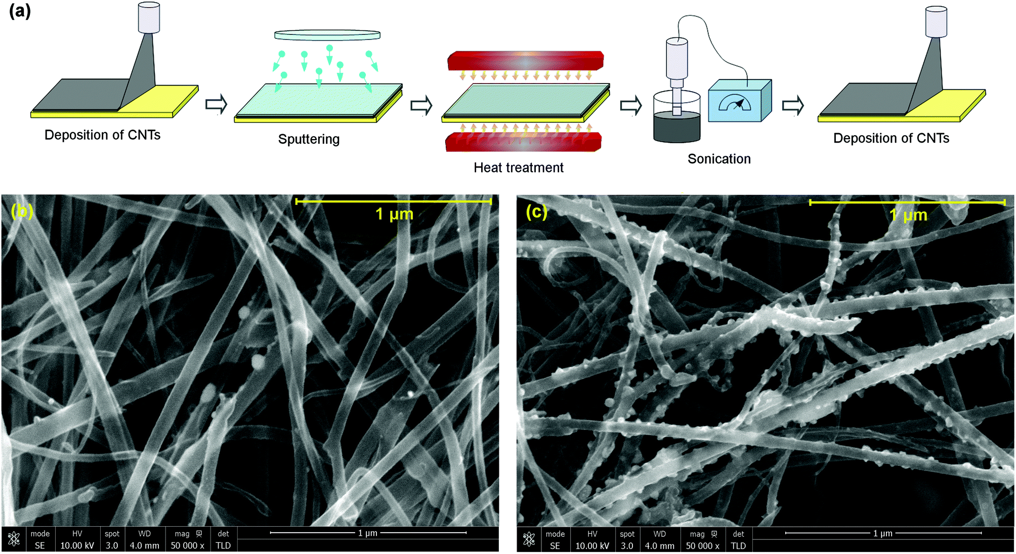 | ||
| Fig. 1 Interaction of N-doped CNTs with Cu. (a) Experimental setup for studying interactions between the CNTs and metal matrix. SEM images of Cu sputtered on (b) N-free CNTs and (c) N-doped CNTs after vacuum heat-treatment at 500 °C followed by sonication in acetone. Sonication in acetone removes most of Cu particles from nitrogen-free nanotubes while non-heat treated (N-doped) nanotubes are still coated. | ||
2.2. Computed structures and mechanical properties
In order to understand the influence of CNT surface modifications on the structural, mechanical and electronic properties of the composite system, we have performed first principles calculations on various Cu-fCNT composite systems shown schematically in Fig. 2(a). We have considered four different surface modifications, namely oxygenation, carboxylation, amination and N-doping, of three different CNTs embedded in a Cu matrix. Composites containing such modified CNTs are denoted Cu–O–CNT, Cu–OO–CNT, Cu–N–CNT and Cu–nCNT, respectively. Two of the CNTs considered are single-walled, (5,5) and (6,4), and one is double-walled, (10,10)@(5,5) (see Fig. S6 in the ESI†). Doping takes place by substitution of a C atom by a N atom, whereas covalent functionalization involves the presence of functional groups around the lateral surface of the CNTs. In case of substitutional doping, only graphitic N atoms are considered. After heat treatment it is assumed that hydrogen atoms connected with the functional groups have dissociated from the system. Most of the calculations were carried out using a rectangular 7 × 7 × 8 supercell of ca. la = lb = 18.2 Å and lc = 7.4 Å and focused on the (5,5) nanotube whose atomistic cross-sectional and side views are shown in Fig. 2(a). This corresponds to a CNT density of about 3.0 × 1013 cm−2. Due to the 3D periodic boundary conditions, our composite model can be viewed as a grid of infinitely long parallel CNTs embedded in a Cu matrix allowing for the best representation of individual nanosized CNTs and their macrostructure.10,14 Each CNT was placed inside a predefined cylindrical cavity in the fully optimized fcc bulk Cu. The size of the cavity and the CNT orientation in the Cu matrix were carefully chosen to minimize the lattice mismatch between the metal and the carbon nanotube9,11,43 including the optimal separation distance between Cu and C atoms (1.9–2.4 Å (ref. 44 and 45)).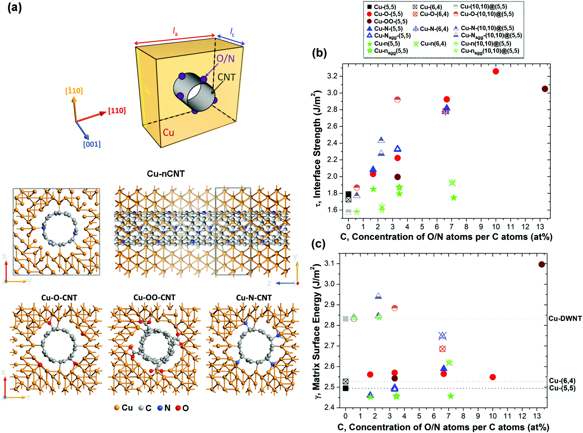 | ||
| Fig. 2 Structural and energetic properties of Cu–fCNT composites. (a) Upper panel: Schematic view of the model used for the structural and elastic calculations of the Cu–fCNT composites. Middle panel: Atomistic cross-sectional and side views of fully optimized Cu-n(5,5) system. For clarity, some layers of Cu atoms in the side view are drawn with different degrees of transparency. Supercells are marked by grey lines. Bottom panel: The cross-sectional views of the composites containing oxygenated, carboxylated and aminated CNTs. (b) The interface strength τ, and (c)the matrix internal surface energy γ as a function of the concentration of dopants/adsorbates. Seventeen different Cu–CNT composite systems were considered as indicated by the different symbols. Subscript “agg” refers to systems with aggregated dopants or adsorbates. | ||
The structural and chemical stability of the embedded CNTs together with the formation of favourable metal–CNT interfaces have been identified as critical in determining the strength of the composites as well as enhancing their electrical performance.11,15,17,19,23,46 Therefore, we start by presenting an analysis of the structural stability of the Cu-fCNT composites studied in this work. This stability can be assessed using a combination of the interfacial strength τ the matrix internal surface energy γ and the degree to which the CNT structure is distorted defined by the coefficient of CNT radius variation CV11 (see ESI† for details). High τ indicates strong bonding between the CNT and the metal matrix implying the formation of a continuous or quasi-continuous metallic layer around the nanotube. Low γ suggests a tendency for the CNT to de-adhere possibly leading to the formation of metal clusters on the surface. Higher CV values indicate a greater disturbance to the sp2 carbon network. Fig. 2(b) and (c) show how the interface strength τ and the matrix internal surface energy γ for each type of Cu–fCNT composite considered vary with the concentration of O/N atoms relative to the number of C atoms in the nanotube. As expected,15,23,24,26–28,47 the presence of functional groups on the lateral surface of the CNT enhances its binding with the Cu. Among all surface modifications, covalent functionalization improves the interface strength the most. Comparing the aminated (Cu–N–CNT), carboxylated (Cu–OO–CNT) and oxygenated (Cu–O–CNT) composite systems clearly shows that oxygenation and amination are the most efficient ways of improving the Cu–CNT interface strength. Oxygenation competes with nitrogen functionalization at higher concentrations (cf. blue triangles and red dots in Fig. 2(b)) as indicated by the higher τ. All Cu–O–CNT systems considered also have higher γ than the pure Cu–CNT composite suggesting that this type of functionalization slightly improves solid–solid wetting. In contrast to previous theoretical studies of binding a single Cu atom to a single walled CNT (SWNT) functionalized with various oxygen bearing groups,26 our calculations on the Cu–O–SWNT and Cu–OO–SWNT composites immediately show that oxygenation gives better results than carboxylation. Cu–O–SWNT systems are characterized by slightly higher τ and much smaller CV than Cu–OO–SWNT systems (see Table S1 in the ESI†). As opposed to oxygenation, the carboxylated composite not only creates –COOH surface groups but also simultaneously forms a vacancy defect which significantly weakens the carbon network.46,48 Moreover, above a certain concentration of carboxyl groups, carboxylation may cause the CNTs to aggregate,49 thus making strong carboxylation useless for solving one of the critical issues in the processing of Cu–CNT composites.15 Further carboxylation may even lead to complete deterioration of the CNT structure.48,50,51
Substitutional doping with nitrogen causes the smallest structural changes to the CNT backbone for all surface modifications investigated (see Tables S1, S2 and S3 in the ESI†). However, it does not improve the Cu–CNT interfacial strength as much as covalent functionalization. Matrix internal surface energies (γ) of the Cu-n(5,5) and Cu-n(10,10)@(5,5) systems are lower than, or comparable with, the corresponding undoped systems indicating that such surface modification does not improve wetting. Interestingly, all surface modifications considered increase τ and γ beyond that of the pure system for a composite containing a semiconducting (6,4) CNT suggesting that the improvement in wetting depends on the character of the CNT that is embedded.
Adhesion between the metal matrix and the fCNT also depends on the particular arrangement of functionals. An energetically favourable47,48 uniform distribution of functional groups over the nanotube surface improves the interfacial bonding between functionalized double walled CNTs (DWNT) and the Cu matrix (cf. half-filled blue triangles in Fig. 2(b)). The difference in τ between Cu-fSWNT systems with two functionals oriented either as close as possible or as distant as possible, is negligible. A different trend can be observed for systems containing N-doped CNTs. When N atoms, separated by at least one C atom,37 accumulate on one side of the tube, the tube displaces toward the Cu matrix on that side. The effective reduction in separation distance improves the adhesion of the CNT to the metal matrix. The differences in τ between systems having accumulated and homogeneously distributed nitrogen dopants are seen for composites containing both SWNTs and DWNTs (see green stars in Fig. 2(b)).
Good interfacial bonding enables not only a homogeneous distribution of CNTs in the metal matrix but also facilitates the load transfer between them and, consequently, enhances the mechanical properties of the composite.15,22,23 However, covalent functionalization of CNTs strongly affects their structure, disturbing the fragile sp2 network and reducing their stiffness.32,48,52–55 The reduction in CNT elastic modulus depends on the type of functional and its concentration. Therefore, it is important to analyse the influence of both factors on the mechanical properties of the Cu–fCNT composites. To do so, we have applied a small uniaxial tensile strain to their equilibrium structures along the ẑ (longitudinal) axis and calculated the response, i.e. the corresponding component of the stress tensor. Fig. 3 shows how one of the most important elastic constants of a Cu–fCNT composite, the Young's modulus (see ESI† for details), is affected by the different types of functionalization and their concentration.
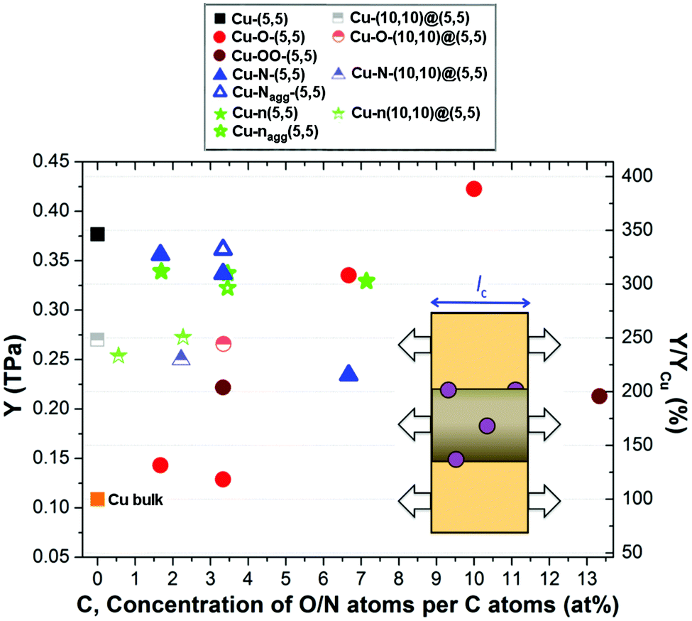 | ||
| Fig. 3 Elastic properties of Cu–fCNT composites. Young's modulus Y of the Cu–fCNT composites as a function of dopant concentration. The change in Young's modulus with respect to pure bulk Cu (along [001]) is depicted on the right axis. The direction of applied strain is indicated by arrows on the schematic inset of the system. | ||
For better comparison, the relative change in Young's modulus of the Cu–fCNT composite with respect to pure bulk Cu is presented on the right axis. It is worth noting that the calculated elastic modulus of bulk Cu is in good agreement with reported experimental values,56,57 while the calculated moduli of the Cu–CNT composites are 2–3 times higher than previously cited19,22 depending on the nanotube type. The elastic properties of the composite depend strongly on the concentration and orientation of the CNTs in the Cu matrix. Previous experiments58 have shown that the largest enhancement can be obtained for composites containing a certain CNT concentration. Our results indicate that composites containing pure single walled nanotubes are characterized by a higher Young's modulus than composites containing pure double-walled nanotubes, but the former are much more affected by covalent functionalization since they possess only one wall per nanotube. The reduction of the Cu–CNT composite stiffness with increasing number of CNT walls, also observed in experiments,17 can be associated with a weakening of the interface between the Cu matrix and the CNT due to inter-tubular interactions attracting the inner and outer walls toward the centre of the strand, away from the surrounding Cu.59 Employing covalently functionalized SWNTs can result in a 66% reduction in the Young's modulus compared to the pure Cu-SWNT composite, although this is still larger than that of bulk Cu. Comparison of composite systems containing different types of functionals reveals a striking difference between Cu–O–CNT and other composites containing covalently functionalized CNTs. The Young's modulus of the Cu–O–CNT composite increases with increasing concentration of functional groups, in agreement with previous experimental results,23 whereas the Young's moduli of the Cu–OO–CNT and Cu–N–CNT composites follow the opposite trend. This is because oxygenation effectively improves the bonding between the CNTs and the Cu matrix causing only small structural changes to the nanotube backbone (see Fig. 2(b) and Table S1†). Interestingly, nitrogen doping of the CNT reduces by only a small amount the Young's modulus of the composite containing SWNTs and was found to slightly improve the stiffness of the composite containing DWNTs, in the N concentration range considered (see green stars in Fig. 3). The elastic properties of the fabricated composite depend strongly on the quality of the CNTs utilized, especially in the case of SWNTs. As our calculations show, the mutual orientation of functional groups and N-dopants around the CNT can cause the differences in the stiffness of the resultant composite.
2.3. Computed electronic properties
To determine whether CNT functionalization can enhance the electrical properties of the composite it is first necessary to analyse the ground-state electronic properties of all the Cu–fCNT systems studied and with this in mind Fig. 4 presents their projected density of states (PDOS). As earlier investigations show,9,11 the total DOS of a pure Cu–CNT composite system is dominated by Cu states and does not resemble the intrinsic electronic structure of the CNT (see Fig. S7 in the ESI†). The weak coupling between Cu-d and C-p orbitals causes inefficient electrical conduction and therefore modification of the composite's components is required if its transport properties are to be improved.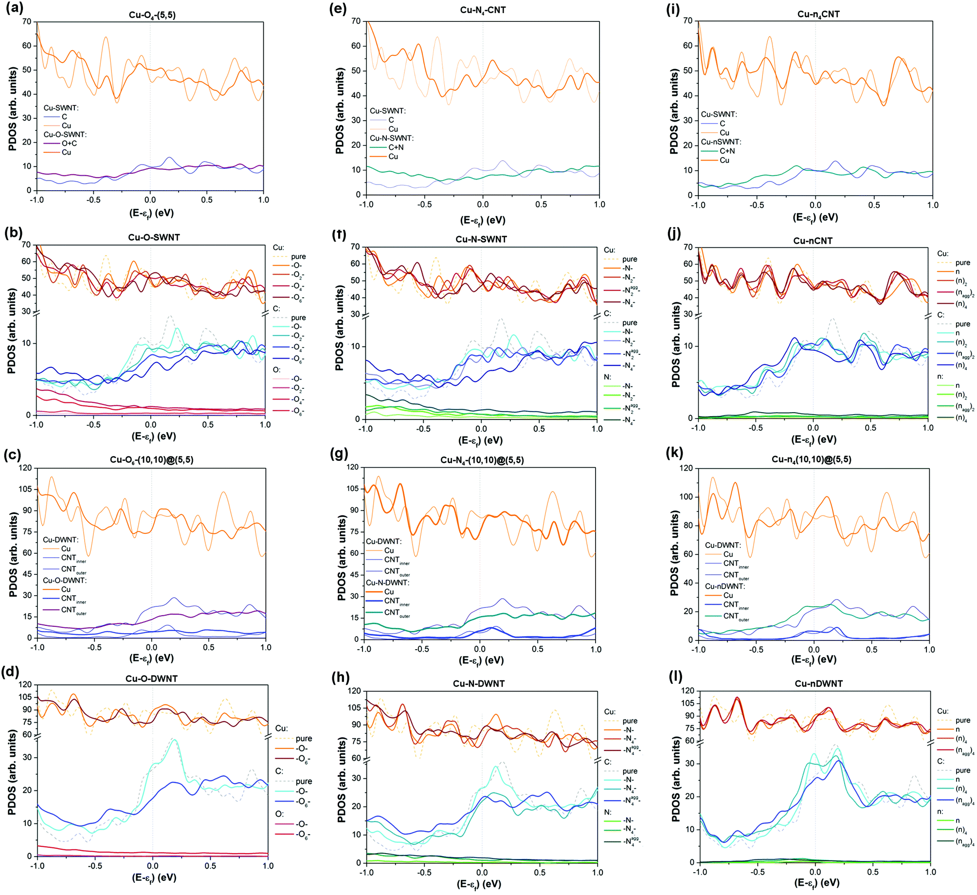 | ||
| Fig. 4 Electronic properties of Cu–fCNT composites. Projected density of states (PDOS) of all Cu–fCNTs composites considered: (a)–(d) Cu–O–CNT, (e)–(h) Cu–N–CNT, and (i)–(l) Cu–nCNT systems. εF is the Fermi energy. | ||
Our results indicate that covalent functionalization of SWNTs below 6.7 at% can increase the number of available Cu states at the Fermi level, although the sum of C and O/N states in Cu-fSWNT systems is smaller than the number of C states in the Cu-SWNT system (see Fig. 4(a), (e) and Fig. S9(a), (b) in the ESI†). For Cu-fDWNT systems, where only the outer tube is functionalized, it is also possible to observe an increase in the sum of C and O/N states above the level of the pure composite (see Fig. 4(d) and (h)) for small concentrations of functionals. Importantly, the covalent functionalization of DWNTS can affect not only the level of Cu states and those originating from the outer tube, but also those which are associated with the inner tube (see Fig. 4(g)). Note that a small concentration of oxygen atoms can enhance the total density of states at the Fermi level in both types of functionalization considered – oxygenation and carboxylation, above the level of the pure composite (see Fig. 4(a) and Fig. S8(a) in the ESI†). Clearly, such functionalization introduces new states which can contribute to electron injection and enables the opening of new conduction channels in the composites. Previous theoretical studies26,47 have also shown that the presence of oxygen bearing groups promotes electron exchange between the CNT and Cu, which might improve poor charge transfer along the side contacts in Cu–CNT composite systems.9,11 However, our results show that the type, concentration and spatial distribution of functional groups need to be carefully adjusted. As can be seen in Fig. 4(b), (d), (f) and (h), increasing concentration of groups decreases the number of available states at the Fermi level. Comparison between Cu–O–CNTs (see Fig. 4(b) and Fig. S9(a) in the ESI†) and Cu–N–CNTs (see Fig. 4(f) and Fig. S9(b) in the ESI†) reveals that a small concentration of oxygen bearing groups has slightly more positive impact on the electronic properties of the composite than amines, regardless the metallic/semiconducting character of the nanotube. Further analysis indicates that the spatial localization of groups also plays an important role, in both types of system, Cu-fSWNT and Cu-fDWNT. Aggregation of groups between the CNT and the Cu matrix effectively reduces the separation distance between them thereby forming a better interface, which is signalled by more states at the Fermi level compared to the case of homogenously distributed groups. It also needs to be emphasized that, above a certain threshold, covalent functionalization adversely affects the electronic properties of the composite reducing not only the number of states which are associated with the CNT but also those originating from neighbouring Cu atoms (see Fig. 4(c)).
N-doping has a different influence on the electronic properties of the composite since no new covalent bonds between the CNT and the Cu matrix are formed, although it can improve interfacial adhesion. As opposed to covalent functionalization, substitutional doping of SWNTs does not increase the number of available Cu states at the Fermi level, even for small concentrations of N atoms (see Fig. 4(i), (j) and Fig. S9(c) in the ESI†). However, for a particular range of N doping, an increase of available electronic states at the Fermi level associated with the tube itself is clearly apparent. As can be seen in Fig. 4(j), the density of C states in the Cu-nSWNT composite is higher than the original level in the undoped system for 3.45 at% concentration of N atoms per number of C atoms in the nanotube, but is lower for 1.67 at% and 7.14 at% concentrations, respectively. Closer inspection reveals that the distribution of N atoms around the lateral surface of the CNT plays an important role. The composite system containing a CNT doped with N atoms which are homogenously distributed around the nanotube has a smaller number of conducting channels than the system with the same concentration of N atoms but where these atoms are located closer to each other. This suggests that the local concentration of N atoms also needs to be in the proper range.
The positive effect of N-doping on the electronic properties of the composite is more pronounced in the Cu-nDWNT systems. As can be seen in Fig. 4(k), the effect of the excess number of free electron charge carriers that nitrogen doping introduces is clearly apparent through an increase in the total available electronic states at the Fermi level. The number of available states at the Fermi level originating not only from the outer tube, but also the inner tube and the Cu matrix is increased with respect to the undoped system. Similar to the situation in Cu-nSWNT composites, the total number of conducting channels in Cu-nDWNT systems depends strongly on the concentration, mutual orientation and distribution of dopants (cf.Fig. 4(j) and (l)).
The results of the electronic structure analysis suggest that small concentrations of all types of functional groups and N-dopants increase the number of available conducting channels. However, the number of conduction channels constitutes only the upper limit of the conductance. Further analysis of the transport properties of Cu–fCNT systems is required to enable us to predict which CNT modification will improve the electrical performance of the composite.
2.4. Computed transport properties
The transport calculations have been performed mainly on the device models shown schematically and atomistically in Fig. 5(a). The central part of each model, sandwiched between two semi-infinite copper electrodes, consists of the same supercell utilized in the previous structural, mechanical and electronic properties analysis but doubled in size. For computational convenience, we focused on Cu-f(5,5) systems, however test calculations on composites containing a double-wall CNT and a chiral nanotube were also performed and showed similar trends11 (see also Fig. S10(a) in the ESI†). Considering the results of the preceding analysis on the electronic properties, we have chosen for further study Cu–O–CNT, Cu–N–CNT and Cu–nCNT composites containing no more than 7.2 at% of O/N atoms per number of C atoms in the nanotube (below 0.3 wt% of O/N atoms in the composite) since they seem the most promising.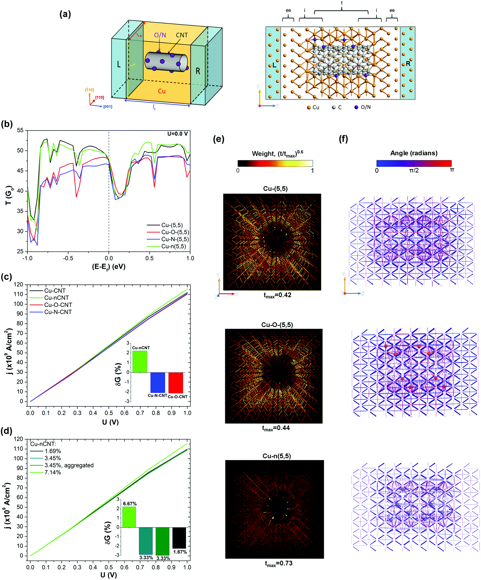 | ||
| Fig. 5 Transport properties of Cu–fCNT composites. (a) 3D visualisation and atomistic side view of the model used for the transport calculations of Cu–fCNT composite systems. The semi-infinite electrodes consisting of perfect copper are depicted in blue. For clarity, some metal layers from the side view have been removed. ee denotes the extended electrode region, i is the interface region and t is the transport region. (b) The zero-bias transmission spectra for all types of Cu-f(5,5) composites containing 8 O/N atoms in the supercell. EF is the Fermi energy. (c)–(d) The current density as a function of applied voltage for all types of Cu-f(5,5) composites and all concentration of dopants in the Cu-n(5,5) composites considered, including aggregates. Insets: The relative change in differential conductance of Cu-f(5,5) composites with respect to the undoped system. (e)–(f) Cross-sectional and longitudinal views of the transmission pathways in the Cu-(5,5), Cu–O-(5,5) and Cu-n(5,5) composites. The thickness of an arrow illustrates the magnitude of the relative local transmission component (t) with respect to the maximum value (tmax) for each system according to the legend. An arrow is only drawn when its magnitude is at least 5% of the maximum local transmission. The colour of an arrow on the side views depends on the direction of the local flow, according to the colour bar. The positions of the oxygen (red) and nitrogen (blue) atoms are shown on the side views. | ||
The zero-bias transmission spectra for each Cu–fCNT composite system studied and containing the same number of O/N atoms (eight) are presented in Fig. 5(b). In general, the transmission spectra within the chosen energy window are similar and indicate that the transport channels are completely delocalised.9,11 However, closer inspection reveals that only nitrogen doping preserves transmission through the composite to the same degree as the pure Cu–CNT system, within the presented energy range. Covalent functionalization significantly suppresses the transmission channels below the Fermi energy. At the Fermi level, the transmission coefficients of both Cu–nCNT and Cu–O–CNT systems increase above the values of the pure composite, while the value for the Cu–N–CNT system almost reaches this level suggesting that electron transport through all systems is rather similar. For electron energies higher than the Fermi energy, the transmission coefficients of all systems become comparable to the pure composite values, when it starts to differ again, increasing for Cu–nCNT and decreasing for Cu–N–CNT and Cu–O–CNT.
The application of a finite bias voltage to all these systems allows us to observe how different types of functionalization influence the current density and the conductance. Consistent with previous experimental findings,23,24Fig. 5(c) shows that covalent functionalization of CNTs leads to a small reduction in the current density and in the differential conductance of the composite. Detailed analysis of the Cu–N–CNT system (see Fig. S10(b) and (c) in the ESI†) containing different amounts of amine reveals that the electrical properties depend strongly on the concentration of functional groups. As the degree of covalent functionalization increases so does the electrical resistance of the composite. Also, aggregation of functional groups on the CNT surface does not favourably affect the transport properties of Cu–N–CNT systems. Interestingly, upon application of a finite voltage, the resistance of Cu–N–CNT systems decreases. For a small concentration of homogeneously distributed amines, the resistance the Cu–N–CNT composite can even be reduced below that of the pure composite in the high bias regime (U ≥ 1 V). As clearly seen in Fig. 5(b), among all CNT modifications studied, only nitrogen doping effectively increases the current density and improves the conductance of the composite with respect to the pure Cu–CNT system. Importantly, the beneficial effect on the transport properties of the composite can only be observed above a certain concentration of dopants (see Fig. 5(d)). In contrast to the adsorbates, the mutual orientation of the substitutional dopants has little effect on the conductance of the Cu–nCNT systems, thus making this surface modification a practical method for boosting the electrical performance of the composite system. Furthermore, this result directly indicates that, contrary to alloying the Cu matrix to improve conductance,11 it is possible to establish efficient ‘side’ contact between the Cu matrix and the CNT by an appropriate surface modification of the latter. The ‘side’ type of the contact, which incorporates metal atoms around the lateral surface of the CNT, should also maximize the binding of the CNT to the Cu matrix thereby enhancing the overall mechanical properties of the composite. In summary, the calculations strongly suggest that Cu–CNT composites whose conductance and strength are simultaneously and significantly improved are viable and can be formed when the synthesis and doping conditions are chosen appropriately.
As shown in previous work,11 current injection at a CNT/metal interface is not only related to a high density of delocalized states at the Fermi level throughout the interface region, but also to a favourable interface geometry and a low interfacial potential barrier reducing contact resistance. To understand why covalent functionalization, as opposed to N-doping, does not effectively improve the electrical transport properties of the composite, it is necessary to discuss further the interface geometry and potential barrier. The composite systems containing covalently functionalized nanotubes are characterized by slightly higher CV values than the Cu–nCNT system with a comparable concentration of N atoms (see Table S4 in the ESI†). The disruption of the CNT structure is higher in the oxygenated case than the aminated case. Further analysis of the interface morphology corroborates these observations. The separation distance between the CNT backbone and the surrounding Cu matrix is smaller in Cu–nCNT compared to the two covalently functionalized systems. However, it should be noted that the separation distances of all the systems considered are close to that of the pure system. Also, the heights of the potential barriers in the functionalized composite are rather comparable to the pure composite.
To gain further insight into the calculated results we have investigated the local charge transmission mechanism on an atomic scale. Fig. 5(e) and (f) show the transmission pathways for the pure Cu–CNT, Cu–O–CNT and Cu–nCNT composites through their cross-section and along their longitudinal axis, respectively. The electron flow is represented by arrows in the direction of the chemical bonds between the atoms. For better illustration of the local transmission mechanisms in the interface region, the transmission pathways have been normalized with respect to the largest value of the local transmission component tmax in each plot, scaled, and drawn only above a 5% threshold. The thickness of an arrow illustrates the relative local transmission component with respect to the maximum value in each system. Arrows in Fig. 5(f) are coloured from blue to purple when the transmission components are in the direction of net current flow, whereas colours from purple to red indicate the opposite direction, thereby reducing the overall conductance. Comparison between the Cu–CNT and Cu–O–CNT systems reveals that the transmission pathways in the Cu matrix immediately next to the oxygen groups are significantly quenched around them. A similar effect is induced by the presence of amines on the CNT surface (see left panel in Fig. S11 in the ESI†). The presence of oxygen surface groups also suppresses the electron transmission through nanotube itself. The transmission pathways through the CNT in Cu–O–Cu system are hardly visible in Fig. 5(e). A closer look on the corresponding plot in Fig. 5(f) shows relatively thick red arrows next to the oxygen atoms implying that the main back scattering in the Cu–O–CNT system is caused by oxygen atoms. Interestingly, nitrogen atoms in the Cu–N–CNT system do not cause such a strong back scattering effect leaving the conduction channels in the CNT similar to those in the pure system (cf. first plot in Fig. 5(f) and right panel in Fig. S11 in the ESI†). As opposed to covalent functionalization, nitrogen doping almost doubles locally the transmission through the nanotube and to a small extent reduces back scattering in the Cu matrix around the CNT with respect to the pure system. This explains the differences in the transport properties of the Cu–fCNT composites shown in Fig. 5(c).
Finally, we have tested the most promising surface modification, N-doping, on “carpet” composites which can be utilized in vertical vias within microelectronic interconnects, e.g. in batteries. As illustrated in the inset of Fig. 6, we have constructed a model of closely packed, vertically aligned, CNTs connected at both ends to the Cu matrix. To reproduce experimental conditions, in which copper on the nanoscale does not penetrate the space between the CNTs within the dense carpet,11 the dimensions of the supercell perpendicular to the longitudinal axis of the nanotubes were reduced to ca. 10 Å and Cu atoms were excluded from the space between them. The lack of connecting metal matrix between neighbouring CNTs results in a higher potential barrier for holes and the electrons at the end interface and, consequently, in an overall smaller current density compared to the fully embedded Cu–CNT composite system (cf. Tables S4 and S5 in the ESI†). The reduction in current density can be effectively overtaken by N-doping of the CNT (see Fig. 6). The current density of the N-doped system becomes nearly 160% greater than the undoped carpet system when U = 1 V and almost as high as of the best bimetal carpet systems, Cu–Ni-((5,5) carpet).11 This result underpins the argument that N-doping of CNTs, is another effective method for creating highly conductive Cu–CNT composite systems.
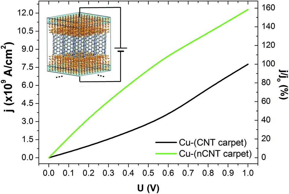 | ||
| Fig. 6 Transport properties of carpet systems. Current density as a function of applied voltage for “carpet” systems with and without N-doping. The computational model is presented in the inset. The relative changes in current density with respect to the undoped carpet system are depicted on the right axis. jo is the current density of the Cu-(CNT carpet) system when U = 1 V is applied to electrodes. | ||
3. Conclusions
In summary, we have presented a simple method for addressing the problem of poorly interacting metal–carbon interfaces in Cu–CNT composites. Our method predicts simultaneous enhancement of both the mechanical and electron transport properties of the composite. Density functional theory calculations supported by sonication experiments show that nitrogen doping of CNTs can effectively improve adhesion between them and the Cu matrix, and hence the mechanical properties and most importantly the electrical performance of the composite. Moreover, our calculations indicate that nitrogen doping can improve the electrical conductance of Cu sputtered CNT carpets by ∼160% compared to the undoped system. In addition, we show that covalent functionalization of CNTs, which in general greatly disturbs their structure, can significantly improve adhesion and CNT wetting by Cu. In effect the mechanical properties of the Cu–CNT composite are enhanced, if the concentration of functionals is below 6.7 at%. In particular, oxidative pre-treatment of the CNTs increases the Young's modulus of the composite by up to 289% above that of pure Cu. Furthermore, our theoretical model clearly explains why such surface modification, contrary to substitutional doping of CNTs, does not effectively improve the electrical performance of the composite. Functional groups, especially those containing oxygen atoms, act as carrier traps reducing the carrier density and increasing back-scattering in the system, whereas nitrogen dopants almost double locally the transmission through the nanotube and reduce back scattering in the Cu matrix around the CNT. By understanding the nature of the interactions between Cu and the functionalized CNT, a practical method could be developed for preparing ultra-strong and ultra-conductive Cu–CNT composites that will help improve the efficiency of power distribution around the world.4. Methods
4.1. Synthesis of N-doped CNTs
Nitrogen doped carbon nanotubes were synthesised by a chemical vapour deposition method within a horizontal quartz reaction tube. The synthesis setup was composed of a pre-heater, furnace, quartz reaction tube, injection pump with a syringe, inert gas flow meter and exhaust purifier as presented in Fig. S1 in the ESI.† The feedstock solution for the growth of N-doped nanotubes was composed of ferrocene (Acros Organics, 98%), toluene (Acros Organics, 99+%) and Pyrazine (Sigma Aldrich, 99+%). Ferrocene was used as a source of the metal catalyst (iron) and carbon. Pyrazine was used as a source of nitrogen. Toluene was used as a solvent for ferrocene and the main source of carbon. A solution of 3 wt% ferrocene and 30 wt% of pyrazine in toluene was injected into a preheater (180 °C) and feedstock vapour was transported by argon carrier gas (flow rate 0.7 L min−1) to the hot zone of the reactor tube (760 °C).4.2. Characterisation of CNT carpets
After 4 h of synthesis, approximately 200 μm long nanotubes were collected from the reactor tube and analysed using Scanning Electron Microscopy (SEM), Thermogravimetric analysis (TGA) and Raman spectroscopy.SEM observation was made using a Nova NanoSEM 450 scanning electron microscope. After each synthesis, the cross sections of the CNT carpets were examined using SEM in order to analyse the length, diameter and alignment of the nanotubes, whereas SEM observation of the top and bottom surfaces allowed evaluation of surface purity (see Fig. S2 in the ESI†).
TGA analysis was carried out using the TGA Q500, TA Instruments (see Fig. S4 in the ESI†). 5 mg samples were heated in air (60 ml min−1) from room temperature up to 1000 °C (heating rate of 20 °C min−1).
Raman characterisations were made using a Renishaw Ramascope-1000 system with a 632.8 nm red laser (see Fig. S5 in the ESI†). Before analysis, the device was calibrated using a silicon wafer with a characteristic Raman spectra showing a sharp peak at a wavenumber of 521 cm−1. From each synthesis, five randomly collected samples were analysed for 10 s exposure time, 100% laser power, grating with 1200 grooves per millimeter (g mm−1), 100–3200 spectrum range and one accumulation. Curve fitting and reading of peak parameters was made using Wire 3.3 software.
4.3. Heat treatment of CNT carpets
Heat treatment was performed using a Webb 134 Red Devil high vacuum furnace (see Fig. S3 in the ESI†). CNT carpets were placed within a graphite crucible with lid and the furnace was pumped down to 10−7 mbar prior to heating. In order to remove N completely from the samples,41 heating up to 2000 °C was carried at a rate of 20 °C min−1 and holding for 10 minutes at the target temperature.4.4. Sputtering of CNT carpets with Cu
As-made N-doped CNTs and heat-treated N-free CNTs were sputtered with copper (99.99% copper target) using an Emitech K575 Sputter Coater, Emitech Ltd, Ashford Kent, UK. The sputtering time was maintained at 360 seconds.4.5. Structural, mechanical and electronic property calculations
The structural, mechanical and electronic properties of the Cu–fCNT composites were calculated within the framework of spin-polarized Density Functional Theory (DFT)60 as implemented in the Atomistix ToolKit (ATK) and SIESTA numerical packages61 The computations were carried out employing the Generalized Gradient Approximation (GGA) with the Perdew–Burke–Ernzerhof (PBE)62 parameterization for the exchange–correlation functional and a double-ζ numerical basis set of orbitals localized on atoms with polarization functions (DZP). Long-range dispersion interactions were included in the total binding energy as proposed by Grimme.63 The Brillouin zone was sampled using a 3 × 3 × 3 Monkhorst–Pack scheme, whereas the kinetic energy cutoff for real-space integration was set at 150 Ry for the structural and mechanical calculations and increased up to 300 Ry for the density of states calculations. The self-consistent field (SCF) cycle was iterated until and the density matrix changed by less than 0.002 Ry. The composite models schematically presented in Fig. 2(a) were fully optimized until the maximum force converged to less than 0.03 eV Å−1 and the total energy changed by less than 10−4 eV per atom. Further computational details are given in the ESI.†4.6. Electron transport calculations
The electronic coherent transport calculations were performed employing the non-equilibrium Green's function (NEGF) technique, within the Keldysh formalism as implemented in the TranSIESTA and ATK codes.61b All systems were treated as two-probe systems with the central scattering region sandwiched between fully relaxed semi-infinite source (left) and drain (right) copper electrode regions as presented in Fig. 5 and 6. Both electrodes and their extensions (ee) in the central scattering region of the Cu-SWNT full composite models contain 7 × 7 × 2 atoms (ca. 18.2 × 18.2 × 3.7 Å3), whereas for the Cu-DWNT their size was extended to 10 × 10 × 2 atoms (ca. 25.9 × 25.9 × 3.7 Å3). The total length of each device (ca. lc = 34 Å) was smaller than the electron mean free path in copper (ca. 400 Å) allowing for calculations in the ballistic regime. Due to the size of the system, the energy window for calculating the transport properties was chosen in the range of (−1,1) eV, using 51 points. The Brillouin zone of the two-probe system was sampled using a 1 × 1 × 100 Monkhorst–Pack scheme. The calculations were performed at 300 K. Other computational details are the same as given in the previous section. More details of the method for calculating the transport properties are provided in the ESI.†Conflicts of interest
There are no conflicts to declare.Acknowledgements
This work has been supported by the European Commission through the FP7-NMP programme (project UltraWire, grant no. 609057). We gratefully acknowledge the Cambridge High Performance Computing Cluster and the Interdisciplinary Centre for Mathematical and Computational Modelling at the University of Warsaw (Grant No. G47-5 and G54-8) for providing computer facilities.References
- L. Radushkevich and V. Lukyanovich, Zurn. Fisic. Chim., 1952, 26, 88–95 CAS.
- S. Iijima, Nature, 1991, 354, 56–58 CrossRef CAS.
- C. Subramaniam, A. Sekiguchi, T. Yamada, D. N. Futabab and K. Hata, Nanoscale, 2016, 8, 3888–3894 RSC.
- G. Chai and Q. Chen, J. Compos. Mater., 2010, 44, 2863–2873 CrossRef CAS.
- K. T. Kim, J. Eckert, S. B. Menzel, T. Gemming and S. H. Hong, Appl. Phys. Lett., 2008, 92, 121901 CrossRef.
- G. Chai, Y. Sun, J. J. Sun and Q. Chen, J. Micromech. Microeng., 2008, 18, 035013 CrossRef.
- C. Subramaniam, T. Yamada, K. Kobashi, A. Sekiguchi, D. N. Futaba, M. Yumura and K. Hata, Nat. Commun., 2013, 4, 2202 CrossRef PubMed.
- H.-J. Hwang, S.-J. Joo and H.-S. Kim, ACS Appl. Mater. Interfaces, 2015, 7, 25413–25423 CrossRef CAS PubMed.
- M. Ghorbani-Asl, P. D. Bristowe and K. Koziol, Phys. Chem. Chem. Phys., 2015, 17, 18273–18277 RSC.
- S. Sun, W. Mu, M. Edwards, D. Mencarelli, L. Pierantoni, Y. Fu, K. Jeppson and J. Liu, Nanotechnology, 2016, 27, 335705 CrossRef PubMed.
- K. Z. Milowska, M. Ghorbani-Asl, M. Burda, L. Wolanicka, N. Ćatić, P. D. Bristowe and K. K. K. Koziol, Nanoscale, 2017, 9, 8458–8469 RSC.
- R. Sundaram, T. Yamada, K. Hata and A. Sekiguchi, Sci. Rep., 2017, 7, 9267 CrossRef PubMed.
- L. Lu, Y. Shen, X. Chen, L. Qian and K. Lu, Science, 2004, 304, 422–426 CrossRef CAS PubMed.
- J. Shuai, L. Xiong, L. Zhu and W. Li, Composites, Part A, 2016, 88, 148–155 CrossRef CAS.
- S. R. Bakshi, D. Lahiri and A. Agarwal, Int. Mater. Rev., 2010, 55, 41–64 CrossRef CAS.
- D. Janas and B. Liszka, Mater. Chem. Front., 2018, 2, 22–35 RSC.
- S. M. Uddin, T. Mahmud, C. Wolf, C. Glanz, I. Kolaric, C. Volkmer, H. Höller, U. Wienecke, S. Roth and H.-J. Fecht, Compos. Sci. Technol., 2010, 70, 2253–2257 CrossRef CAS.
- M. Burda, A. Lekawa-Raus, A. Gruszczyk and K. K. K. Koziol, ACS Nano, 2015, 9, 8099–8107 CrossRef CAS PubMed.
- W. M. Daoush, B. K. Lim, C. B. Mo, D. H. Nam and S. H. Hong, Mater. Sci. Eng., A, 2009, 513–514, 247–253 CrossRef.
- P.-M. Hannula, A. Peltonen, J. Aromaa, D. Janas, M. Lundström, B. P. Wilson, K. Koziol and O. Forsén, Carbon, 2016, 107, 281–287 CrossRef CAS.
- D. Janas, K. Z. Milowska, P. D. Bristowe and K. K. K. Koziol, Nanoscale, 2017, 9, 3212–3221 RSC.
- S. I. Cha, K. T. Kim, S. N. Arshad, C. B. Moa and S. H. Hong, Adv. Mater., 2005, 17, 1377–1381 CrossRef CAS.
- K. T. Kim, S. I. Cha, T. Gemming, J. Eckert and S. H. Hong, Small, 2008, 4, 1936–1940 CrossRef CAS PubMed.
- P.-M. Hannula, J. Aromaa, B. P. Wilson, D. Janas, K. Koziol, O. Forsén and M. Lundström, Electrochim. Acta, 2017, 232, 495–504 CrossRef CAS.
- P. Martis, B. R. Venugopla, J.-F. Seffer, J. Delhalle and Z. Meckhalif, Acta Mater., 2011, 59, 5040–5047 CrossRef CAS.
- M. Park, B.-H. Kim, S. Kim, D.-S. Han, G. Kim and K.-R. Lee, Carbon, 2011, 49, 811–818 CrossRef CAS.
- S. Biniak, M. Pakula, G. S. Szymanski and A. Swiatkowski, Langmuir, 1999, 15, 6117–6122 CrossRef CAS.
- N. Khusnun, A. Jalil, S. Triwahyono, N. Jusoh, A. Johari and K. Kidama, Phys. Chem. Chem. Phys., 2016, 18, 12323–12331 RSC.
- Y.-T. Zheng, F.-Z. Xuan and Z. D. Wang, Procedia Eng., 2015, 130, 1184–1189 CrossRef CAS.
- J. Zhao, H. Park, J. Han and J. P. Lu, J. Phys. Chem. B, 2004, 108, 4227–4230 CrossRef CAS.
- K. Z. Milowska and J. A. Majewski, J. Chem. Phys., 2013, 138, 194704 CrossRef PubMed.
- K. Z. Milowska and J. A. Majewski, Phys. Chem. Chem. Phys., 2013, 15, 14303–14309 RSC.
- K. Z. Milowska, Ph.D. thesis, University of Warsaw, 2013 Search PubMed.
- J. E. Moreno-Marcelino, S. Enrique, V. G. Lopez-Tellez and S. Hernandez-Lopez, J. Nano Res., 2014, 28, 51–61 Search PubMed.
- K. Koziol, M. Shaffer and A. Windle, Adv. Mater., 2005, 17, 760–763 CrossRef CAS.
- K. Z. Milowska, M. Woińska and M. Wierzbowska, J. Phys. Chem. C, 2013, 117, 20229–20235 CrossRef CAS.
- M. Woińska, K. Z. Milowska and J. A. Majewski, Phys. Status Solidi C, 2013, 10, 1167–1171 CrossRef.
- J. D. Wiggins-Camacho and K. J. Stevenson, J. Phys. Chem. C, 2009, 113, 19082–19090 CrossRef CAS.
- D. Janas, Vacuum, 2018, 149, 48–52 CrossRef CAS.
- V. G. Ramu, A. Bordoloi, T. C. Nagaiah, W. Schuhmann, M. Muhler and C. Cabrele, Appl. Catal., A, 2012, 431–432, 88–94 CrossRef CAS.
- H. C. Choi, S. Y. Bae, W.-S. Jang, J. Park, H. J. Song, H.-J. Shin, H. Jung and J.-P. Ahn, J. Phys. Chem. B, 2005, 109, 1683–1688 CrossRef CAS PubMed.
- (a) P. R. Couchman and W. A. Jesser, Nature, 1977, 269, 481–483 CrossRef CAS; (b) Y. Shibuta and T. Suzuki, Chem. Phys. Lett., 2010, 498, 323–327 CrossRef CAS.
- A. Maiti and A. Ricca, Chem. Phys. Lett., 2004, 395, 7–11 CrossRef CAS.
- F. Gao, J. Qu and M. Yao, Appl. Phys. Lett., 2010, 96, 102108 CrossRef.
- F. Gao, J. Qu and M. Yao, Physica E, 2011, 44, 146–151 CrossRef.
- M. Alsawat, T. Altalhi, T. Kumeria, A. Santos and D. Losic, Carbon, 2015, 93, 681–692 CrossRef CAS.
- C. Bittencourt, X. Ke, G. V. Tendeloo, S. Thiess, W. Drube, J. Ghijsen and C. P. Ewels, Chem. Phys. Lett., 2012, 535, 80–83 CrossRef CAS.
- K. Z. Milowska, J. Phys. Chem. C, 2015, 119, 26734–26746 CrossRef CAS.
- X. Liu, R. H. Hurt and A. B. Kane, Carbon, 2010, 48, 1961–1969 CrossRef CAS PubMed.
- C.-M. Yang, J. S. Park, K. H. An, S. C. Lim, K. Seo, B. Kim, K. A. Park, S. Han, C. Y. Park and Y. H. Lee, J. Phys. Chem. B, 2005, 109, 19242–19248 CrossRef CAS PubMed.
- R. Sitko, B. Zawisza and E. Malicka, Trends Anal. Chem., 2012, 37, 22–31 CrossRef CAS.
- K. Milowska, M. Birowska and J. A. Majewski, Diamond Relat. Mater., 2012, 23, 167–171 CrossRef CAS.
- P. H. Shah and R. C. Batra, Modeling of carbon nanotubes, graphene and their composites, Springer International Publishing, Switzerland, 2014, vol. 188, pp. 111–134 Search PubMed.
- I. K. Petrushenko and K. B. Petrushenko, Mod. Phys. Lett. B, 2016, 30, 16501181 Search PubMed.
- P. K. Singh, K. Sharma, A. Kumar and M. Shukla, J. Compos. Mater., 2017, 51, 671–680 CrossRef CAS.
- S.-Y. Chang and S.-J. Lin, Scr. Mater., 1996, 35, 225–231 CrossRef CAS.
- D. T. Read, Meas. Sci. Technol., 1998, 9, 676–685 CrossRef CAS.
- X.-Y. Liu, X.-Z. Xiang, F. Niu and X.-J. Bai, Rare Met., 2013, 32, 278–283 CrossRef CAS.
- I. Awad and L. Ladani, J. Nanotechnol. Eng. Med., 2014, 5, 031007 CrossRef.
- (a) P. Hohenberg and W. Kohn, Phys. Rev., 1964, 136, B864–B871 CrossRef; (b) W. Kohn and L. Sham, Phys. Rev., 1965, 140, A1133–A1138 CrossRef.
- (a) Atomistix ToolKit version 2015, QuantumWise A/S (http://www.quantumwise.com); (b) M. Brandbyge, J.-L. Mozos, P. Ordejón, J. Taylor and K. Stokbro, Phys. Rev. B: Condens. Matter Mater. Phys., 2002, 65, 165401 CrossRef; (c) J. M. Soler, E. Artacho, J. D. Gale, A. Garcia, J. Junquera, P. Ordejon and D. Sanchez-Portal, J. Phys.: Condens. Matter, 2002, 14, 2745 CrossRef CAS.
- J. P. Perdew, K. Burke and M. Ernzerhof, Phys. Rev. Lett., 1996, 77, 3865–3868 CrossRef CAS PubMed.
- S. Grimme, J. Comput. Chem., 2006, 27, 1787–1799 CrossRef CAS PubMed.
Footnotes |
| † Electronic supplementary information (ESI) available. See DOI: 10.1039/C8NR07521B |
| ‡ Present address: TCM Group, Cavendish Laboratory, University of Cambridge, 19 J. J. Thomson Avenue, Cambridge CB3 0HE, United Kingdom. |
| § Present address: Cranfield University, School of Aerospace, Transport and Manufacturing, Building 61, Cranfield, Bedfordshire, MK43 0AL, United Kingdom. Tel: +44 (0) 1234 754038; E-mail: k.koziol@cranfield.ac.uk. |
| This journal is © The Royal Society of Chemistry 2019 |