
Highly efficient thermophones based on freestanding single-walled carbon nanotube films†
Stepan A.
Romanov
 *a,
Ali E.
Aliev
b,
Boris V.
Fine
ac,
Anton S.
Anisimov
d and
Albert G.
Nasibulin
*ae
*a,
Ali E.
Aliev
b,
Boris V.
Fine
ac,
Anton S.
Anisimov
d and
Albert G.
Nasibulin
*ae
aSkolkovo Institute of Science and Technology, Nobel Str. 3, Moscow 121205, Russia. E-mail: stepan.romanov@skolkovotech.ru; a.nasibulin@skoltech.ru
bAlan G. MacDiarmid NanoTech Institute, University of Texas at Dallas, Richardson, TX 75083, USA
cInstitute for Theoretical Physics, University of Heidelberg, Philosophenweg 19, 6912, Heidelberg, Germany
dCanatu Ltd., Konalankuja 5, 00390, Helsinki, Finland
eDepartment of Applied Physics, Aalto University, Puumiehenkuja 2, FI-00076 Espoo, Finland
First published on 7th May 2019
Abstract
We present the state-of-the-art performance of air-coupled thermophones made of thin, freestanding films of randomly oriented single-walled carbon nanotubes (SWCNTs). The work demonstrates both experimentally and theoretically that extremely low heat capacity per unit area of SWCNT films allows centimeter-sized thermophones to achieve record sound pressures (normalized to the input power and geometry) in the frequency range of 1–100 kHz. Our SWCNT films have an aerogel structure. We systematically investigated their thermoacoustic performance as a function of the film thickness and purity. On the theoretical side, we obtained an analytic formula for the sound pressure in the ultrasound region and confirmed it by experiments and numerical simulations.
New conceptsFor the first time, we demonstrated that free-standing SWCNT films can be utilized as a material for ultrasound generation, which exhibits state-of-the-art performance. Particularly the efficiency was 4 times greater than the previously reported values. We developed a theoretical model to predict the ultrasound propagation in the space from a thermophone, which takes into account the diffraction effect causing the inhomogeneous sound pressure distribution. This model was verified numerically and experimentally. We utilized the thermoacoustic measurements as a method of indirect estimation of heat capacity and density of conducting nanomaterials. We introduced a method to remove catalyst particles from carbon nanotubes by resistive heating under vacuum conditions. Therefore, we were able to decrease the heat capacity per unit area (HCPUA) of the films and further increase the sound pressure level from our films. |
Introduction
Acoustic waves are usually produced by mechanical vibration of rigid or semi-rigid objects. There exists, however, a different mechanism of sound generation, which is based on the thermoacoustic effect, defined as a direct conversion of heat into acoustic energy. Practically any conducting material under resistive heating caused by alternating current can produce sound due to the thermoacoustic effect. A sound-producing device exploiting this effect is called a “thermophone”. It has a wide bandwidth and does not contain any mechanically vibrating parts.The first thermophone based on a metallic film was discovered at the end of the 19th century by Braun.1 In 1917, Arnold and Crandall2 theoretically explained the thermal origin of sound in thermophones. According to their theory, alternating current causes Joule heating, which leads to temperature oscillations in a conductor, which, in turn, lead to periodic thermal expansion of the surrounding gas and, as a result, generate sound. The principal relation of the theory was 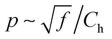 , where p is the sound pressure, f is the output sound frequency (doubled frequency of the applied alternating current), and Ch = ρaC is the heat capacity per unit area (HCPUA). The latter is defined as the product of the heat capacity of material per unit mass, C, and the areal density of the sample, ρa = hρh, where h is the thickness of the sample and ρh is its density. The first thermophones had a low sound pressure and low efficiency, because they were based on metallic films having large thickness and high density, which means high HCPUA.
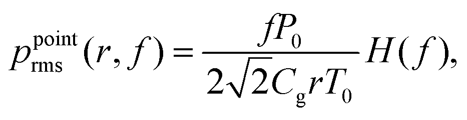
Recent advances in materials science and technology have sparked a new wave of research on thermophones.3 Novel nanomaterials became thinner and sparser. Hence, they had lower HCPUA, which resulted in a significant increase of the sound pressure and made thermophones attractive for many acoustic applications. Experimental investigations with materials having a small HCPUA also shed light on the theory of thermophones. The gas heat capacity of air per unit mass, Cg, was observed to be the new limiting factor for achieving higher sound pressures. In 2008 Xiao et al.4 introduced the relation for the sound pressure of materials with small HCPUA, p ∼ f/Cg.
Promising results for air-coupled thermophones based on different nanostructured conducting materials were observed for gold nanowires,5 poly(3,4-ethylenedioxythiophene):poly(styrene sulfonic) (PEDOT:PSS),6 silver nanowires,7 indium tin oxide (ITO),8 thin titanium film,9 graphene10 and thin aluminum wires11 (Fig. 1). To the date, the best performance in the thermophones was demonstrated by carbon allotropes. Prior to this study, the highest sound pressure level was obtained for freestanding aerogel-type multiwalled carbon nanotube (MWCNT)12 films, which was the consequence of their small HCPUA.
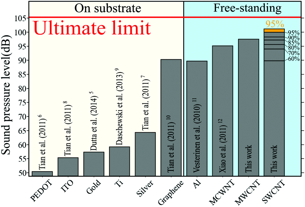 | ||
| Fig. 1 Reported experimental sound pressure level for various thermophone materials at 100 kHz (the sound pressure level for PEDOT, silver, ITO and graphene was measured at 50 kHz and theoretically extrapolated by authors to 100 kHz). The results are normalized to the distance of 3 cm and the input power of 1 W. This work corresponds to freestanding MWCNTs and SWCNT samples of different transmittance. The highest pressure level was measured for the purified sample SWCNT-95% (orange color). Red line: the “ultimate” theoretical limit (defined by eqn (3a) with Ch = 0, r = 3 cm, φ = 0 and θ = 0). The sound pressure level in decibels was normalized with the reference level of 20 μPa. | ||
In addition to having small HCPUA, the aerogel structure of carbon nanotube films (volumetric thermophones) is permeable to gas molecules, which turns these films into very efficient heaters, because the whole volume of the film participates in the thermoacoustic wave generation process. In contrast, for the majority of non-volumetric thermophones, only surface contributes to the sound generation.
Comprehensive theoretical work, which described both surface and volumetric heaters, was recently carried out by Aliev et al.,13 who showed that thermoacoustic equations can be split into the heat and acoustic parts, which can then be solved independently. They obtained the following equation for the root-mean-squared sound pressure, ppointrms, at distance, r, from point-like thermophones
 | (1) |
 , where αT is the gas thermal diffusivity and ρg is the gas density.‡ On the basis of eqn (1), one can define the so-called “ultimate limit” for the thermophone sound pressure in the low-frequency regime: it corresponds to zero HCPUA (Ch = 0), which means χ(f) = 0. The main limitation of eqn (1) is the point-source approximation. It is not applicable when wavelengths become comparable or smaller than the size of the sample. As a result, eqn (1) predicts too large sound pressures at high frequencies.
In this work, we systematically investigated the thermoacoustic performance of SWCNT films as a function of their thickness and purity. The experiments were carried out in the frequency range from 1 kHz to 100 kHz. The main experimental result of the present work is the demonstration of the record thermoacoustic performance of the aerogel-type freestanding single-walled carbon nanotube (SWCNT) films which showed four times higher efficiency in comparison with other thermophone materials under equivalent conditions (see Fig. 1). By decreasing the thickness and purifying the SWCNT films, we obtained the sound pressure level as high as 101 dB (at 100 kHz) when measured at the distance of 3 cm with the input power of 1 W. In addition, we extended the theoretical description of the thermophone sound generation from the point-source regime to the regime of finite and large sources and thereby defined the ultimate limit for the sound pressure in these regimes.
Experimental
Synthesis
The SWCNTs were synthesized in a flow reactor by an aerosol chemical vapor deposition (CVD) method described in detail elsewhere.14 Briefly, the SWCNTs grew on the surface of iron catalyst particles floating in the gas phase in the atmosphere of carbon monoxide at a temperature of 880 °C. The SWCNTs were collected downstream of the reactor in the form of randomly oriented nanotube films (inset of Fig. 2a on the right) on a microporous filter. The method makes it easy to vary the sample thickness depending on the collection time.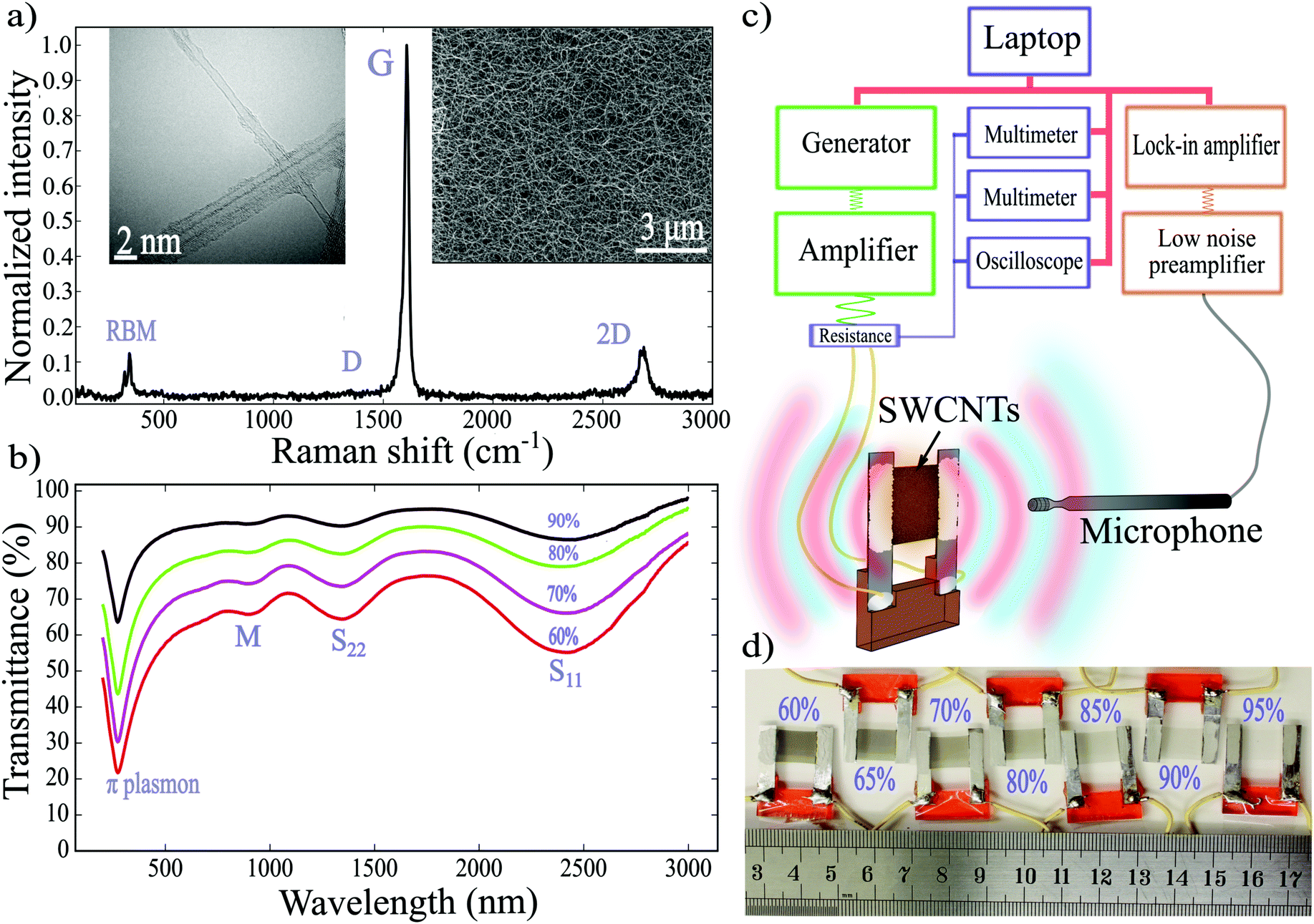 | ||
| Fig. 2 (a) Raman spectrum of SWCNT-90%. Insets show TEM (on the left) and SEM (on the right) images of the produced SWCNTs. (b) Transmittance spectra for SWCNT films of different thicknesses. (c) Schematic diagram of the experimental setup, where the power equipment marked by green color; the sound detection part by orange color and the signal acquisition part by purple color. (d) Freestanding samples of 1 × 1 cm2 SWCNT-N% films (N = 95, 90, 85, 80, 70, 65, 60) named for their optical transmittance at the wavelength of 550 nm. | ||
Characterization
The quality of the SWCNTs was controlled by Raman spectroscopy, ultraviolet-visible-near infrared (UV-VIS-NIR) spectroscopy, scanning electron microscopy (SEM), transmission electron microscopy (TEM) (Fig. 2a and b). The large ratio of G- and D-peaks in the Raman spectrum shown in Fig. 2a (G/D ∼ 100) indicates a low level of defects in the synthesized SWCNTs. The mean diameter of SWCNTs is estimated from Van Hove singularities (S11, S22, M11) in the UV-VIS-NIR spectra (see Fig. 2b) and from the TEM images to be about 2.2 nm. Another important advantage of the filter-based collection is the great flexibility of the further use of the SWCNT films. The films can be easily transferred from the filter onto various substrates and even in the freestanding form, because the SWCNTs have low adhesion to filters.15Samples preparation
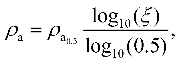
For our experiments, we fabricated samples using the dry-transfer technique.14 We suspended the SWCNT films between two aluminium strips and then covered the strips with a silver paste, for a better electrical contact (see Fig. 2d and a movie in ESI†).14 We kept the sample size of 1 × 1 cm2. Fabricated films had equal density and different thicknesses. Higher thickness corresponded to lower optical transmittance.In experiments, we used films with the following values of transmittances at wavelength 550 nm: 95%, 90%, 85%, 80%, 70%, and 60%, which corresponded to HCPUA of 2.9, 6.0, 9.3, 12.7, 20.4, 30.2 (× 10−3 J m−2 K−1) obtained as Ch = Cρa, where C = 0.72 J g−1 K−1 and
 | (2) |
We also performed additional experiments with purified films, where iron catalyst particles, whose original content was about 17% of film's weight, were removed by means of a high temperature (>1200 °C) annealing under vacuum conditions (see Section S1.2 in ESI†).
Thermoacoustic measurements
The thermoacoustic sound was generated by applying a non-biased alternating current. The experimental setup was designed to measure the dependence of the sound pressure on frequency and on the azimuth angle between the sample and the microphone (see Fig. 2c and Section S1.3 in ESI†). The input power was adjusted to make the average temperature on the surface of the films approximately equal to 80 °C. All the measurements were normalized to the input power of 1 W.Results and discussion
Our main experimental findings are presented in Fig. 3a, which shows plot of frequency-dependent sound pressure level at the point located at the distance of 3 cm from the center of the sample in the direction perpendicular to sample's plane. The plotted data correspond to SWCNT samples of different HCPUA: larger transmittance listed in percent next to each plot corresponds to smaller thickness and hence smaller HCPUA. The value of HCPUA decreases further once the sample is purified by removing iron catalyst particles. The dependence of HCPUA shown in Fig. 3b. As expected on the basis of eqn (1), sound pressure level plotted in Fig. 3a increase with the decrease of sample's HCPUA.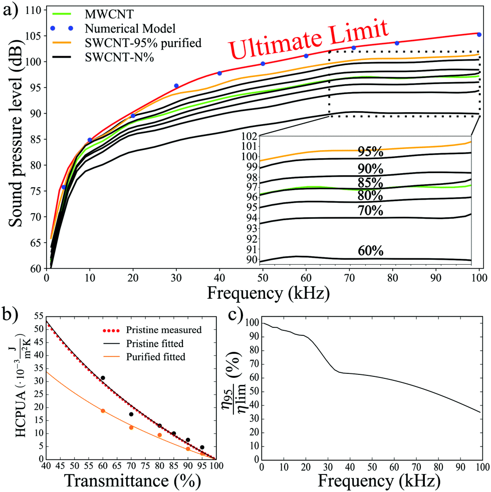 | ||
| Fig. 3 (a) Sound pressure level vs. frequency for various samples normalized to input power 1 W. Black lines: averaged curves for SWCNT-N% (N = 60, 70, 80, 90, 95) samples. Orange line: purified SWCNT-95% sample. Green line: MWCNT sample. Red line: the “ultimate” theoretical limit (defined by eqn (3a) with Ch = 0, r = 3 cm, φ = 0 and θ = 0). Blue points: 3D numerical COMSOL modelling (see Section S2.6 in ESI†). (b) Dependence of HCPUA on transmittance for pristine and purified films. Red dots present HCPUA of pristine SWCNT films measured using areal density from eqn (2). Black and orange dots present HCPUA for pristine and purified films respectively, which were found from fitting of eqn (3a) to the measured sound pressure vs. frequency. (c) The efficiency of purified SWCNT-95% sample normalized to the efficiency in the theoretical limit (eqn (4)). The sound pressure level in decibels was normalized with reference level 20 μPa. | ||
In order to judge the efficiency of thermophones, it is necessary to compare the measured pressures with the ultimate limit of zero HCPUA corresponding to χ(f) = 0. However, as mentioned earlier, eqn (1) gives the correct ultimate limit only at low frequencies (roughly below 16 kHz in our case). In order, to describe generated sound pressures at intermediate and high frequencies, the diffraction correction to eqn (1) must be taken into account as a function of the azimuthal and polar angles towards the microphone.
Before describing the above correction theoretically, let us first present the measured anisotropy of the sound pressure. In order to do this, we placed the purified SWCNT-95% sample on a stepper motor and rotated it with respect to the microphone, changing the angle, θ, in the range of [0,2π], while the sound frequency was fixed at 6, 32, 40, or 64 kHz (Fig. 4). At 6 kHz, we detected nearly isotropic pressure distribution associated with a point-like sound source. At frequencies of 32, 40 and 64 kHz, we observed a transition from the isotropic point-source regime to the anisotropic regime caused by the finite size of the source in terms of the sound wavelength. In the latter regime, the natural diffraction focusing appears in both sides of the sample for θ = 0° and 180°(see Section S2.1 and a movie in ESI†). The transition between the regimes is defined by geometric parameters of the system. In our experimental setting, the wavelength varies from λ = 0.34 cm (at 100 kHz) to 34.3 cm (at 1 kHz), while the sample size and the distance to the microphone are fixed to 1 cm × 1 cm and r = 3 cm, respectively.
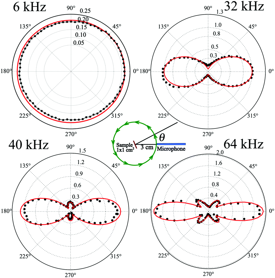 | ||
| Fig. 4 Sound pressure, measured in pascals, dependence of purified SWCNT-95 on azimuthal angle, θ ∈ [0,2π], for frequencies: 6, 32, 40 and 64 kHz. Red lines represent the theoretical limit calculated from eqn (3a) black dots represent experimental data. Measurements were normalized to the input power of 1 W at the distance of 3 cm. | ||
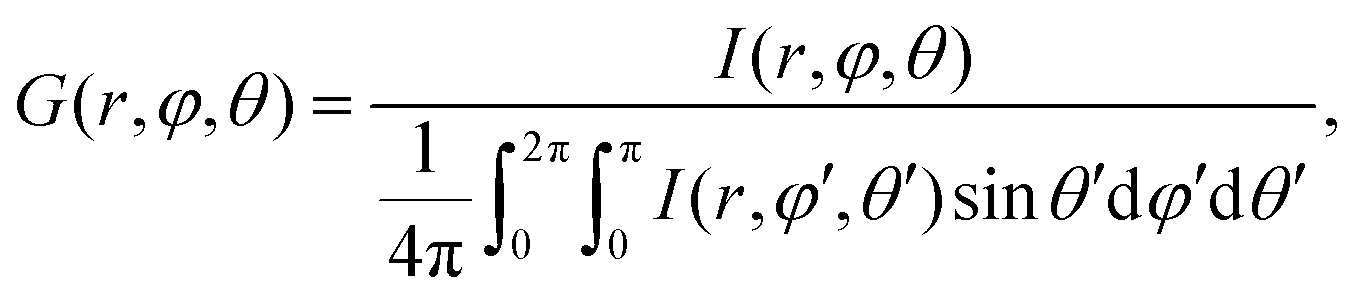
In order to describe all frequency regimes, we theoretically derived the following equation for a surface heater placed in a medium without sound attenuation losses (Section S2 in ESI†):
 | (3a) |
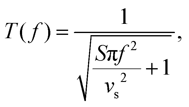 | (3b) |
 | (3c) |
Function T(f) given by eqn (3b) is responsible for the transition between low- and high-frequency regimes for the sound pressure near the sample surface. In terms of wavelength, λ = vs/f, the low-frequency regime corresponds to 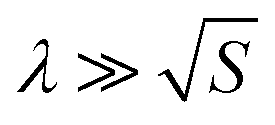 , and the high-frequency regime to
 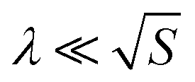 . In derivation of eqn (3a) we used spherical approximation of the sound pressure near a non-spherical sample surface (see Section S2.4 in ESI†). We tested this approximation by direct 3D COMSOL simulations based on coupled Novier–Stocks and Helmholtz equations and found it to be accurate (Fig. 3a, see Section S2.6 in ESI†).
The directivity gain function G(r,φ,θ) defined by eqn (3c) describes the modulation of the sound intensity due to diffraction. We computed it using Huygens–Fresnel principle (see Section S2.5 in ESI†). The experimental measurements presented in Fig. 3a correspond to the direction of the maximum intensity, namely, φ = 0, θ = 0 (shown in Fig. 4). Once G(r,0,0) was obtained, it was substituted into eqn (3a) to find the ultimate pressure limit plotted in Fig. 3a.
We now demonstrate that thermoacoustic measurements can be used as an indirect method to obtain HCPUA and in some cases areal density of materials. In order to do this, we compare the sound pressures predicted by eqn (3a) with the measured sound pressures presented in Fig. 3a. For the freestanding SWCNT films, the HCPUA values were found from the least-squares fitting of eqn (3a) to the sound pressure frequency dependencies using HCPUA as the only fitting parameter. The fitted HCPUA values were then compared with those obtained directly from measurements of areal density with the help of eqn (2). The fitted and measured values of HCPUA were found to be in a very good agreement (see Fig. 3b). This method of obtaining HCPUA can be particularly useful when direct weighing is not possible because of the equipment sensitivity.
The performance of purified SWCNT films without iron catalyst particles was also measured, and then the fitting procedure was repeated for the purified samples (see Fig. 3b). We found that overall HCPUA was indeed reduced by purification, which improved the performance of the SWCNT thermophones.
To demonstrate the effect of volume on the thermophone performance in the aerogel structures we compared surface thermophones from SWCNT films with volumetric thermophone from freestanding films of aligned MWCNTs, which were synthesized by a catalytic CVD method in the form of forests.17 In spite having different values of HCPUA, the samples SWCNT-85% (h ≈ 30 nm, Ch = 9.3 × 10⁻³ J m−2 K−1)16 and MWCNT (T550 = 82%, h ≈ 18 μm, Ch = 19.4 × 10⁻³ J m−2 K−1)17 demonstrated similar sound pressure level (Fig. 3a), due to higher volumetric effect in the MWCNT film. Detailed investigations of the role of the volumetric effect in thermophones will be published elsewhere.
Another way to assess the results presented in Fig. 3a is to look at the efficiency of the measured thermophones. The absolute efficiency of thermophones is defined as the ratio of the average output acoustic power, Pa, to the average applied electric power, P0:
 | (4) |
Let us now enumerate the advantages that make SWCNT films attractive for thermophone applications in comparison with other nanostructured materials. These advantages are in terms of sound generation: (i) the highest sound pressure, (ii) low sheet resistance and (iii) positive temperature coefficient of resistance at high temperatures; and in terms of synthesis: (iv) easy sample handling, and (v) fast, scalable and inexpensive production. The excellent performance of our thermophones opens a new avenue for a number of potential applications. The wide bandwidth and flat amplitude–frequency response of our thermophones can be applied in the devices for calibrations of ultrasound transducers. The possibility to produce thermophones from thin SWCNT films in a flexible shape and with a large surface area allows to make devices with a wide directivity, which can be used, for instance, in robots positioning applications.
Conclusions
To summarize, we demonstrated the state-of-the-art performance of freestanding SWCNTs as a material for thermophone applications. The extremely low HCPUA of 3.2 × 10⁻³ (J m−2 K−1) of the purified SWCNT-95% film allowed our sample to generate a record sound pressure at the frequency of 100 kHz and four fold increase in the efficiency in comparison to previously reported materials utilized in thermophones under equivalent conditions. We also showed the importance of taking into account the anisotropy of sound pressure at high frequencies and modified the equation for the sound pressure of a thermophone to include the effects of diffraction. Finally, we demonstrated the potential of using thermoacoustics as a method for indirect measurement of HCPUA.Conflicts of interest
There are no conflicts to declare.Acknowledgements
Author thanks Dr Vladislav A. Kondrashov for programmable rotating stage, Dr Sergey Yankin for his help with calculations in COMSOL software, Dr Evgenia Gilshteyn for SEM and TEM images and Alexey P. Tsapenko for areal density measurements and Raman spectra. This work was supported by Skoltech NGP Program (Skoltech-MIT joint project). The authors (S. R. and A. G. N.) acknowledge Russian Science Foundation (Project identifier: 17-19-01787) for the support of the experimental part of the research. A. E. A. acknowledges the Office of Naval Research grant N00014-17-1-2521.Notes and references
- F. Braun, Ann. Phys., 1898, 301.6, 358–360 CrossRef.
- H. D. Arnold and I. B. Crandall, Phys. Rev., 1917, 10, 22–38 CrossRef.
- H. Shinoda, T. Nakajima, K. Ueno and N. Koshida, Nature, 1999, 400, 853–855 CrossRef CAS.
- L. Xiao, Z. Chen, C. Feng, L. Liu, Z. Q. Bai, Y. Wang, L. Qian, Y. Zhang, Q. Li, K. Jiang and S. Fan, Nano Lett., 2008, 8, 4539–4545 CrossRef CAS PubMed.
- R. Dutta, B. Albee, W. E. Van Der Veer, T. Harville, K. C. Donovan, D. Papamoschou and R. M. Penner, J. Phys. Chem. C, 2014, 118, 29101–29107 CrossRef CAS.
- H. Tian, D. Xie, Y. Yang, T. L. Ren, T. T. Feng, Y. F. Wang, C. J. Zhou, P. G. Peng, L. G. Wang and L. T. Liu, Appl. Phys. Lett., 2011, 99, 233503 CrossRef.
- H. Tian, D. Xie, Y. Yang, T. L. Ren, Y. X. Lin, Y. Chen, Y. F. Wang, C. J. Zhou, P. G. Peng, L. G. Wang and L. T. Liu, Appl. Phys. Lett., 2011, 99, 253507 CrossRef.
- H. Tian, D. Xie, Y. Yang, T.-L. Ren, Y.-F. Wang, C.-J. Zhou, P.-G. Peng, L.-G. Wang and L.-T. Liu, Appl. Phys. Lett., 2011, 99, 043503 CrossRef.
- M. Daschewski, R. Boehm, J. Prager, M. Kreutzbruck and A. Harrer, J. Appl. Phys., 2013, 114, 114903 CrossRef.
- H. Tian, T. L. Ren, D. Xie, Y. F. Wang, C. J. Zhou, T. T. Feng, D. Fu, Y. Yang, P. G. Peng, L. G. Wang and L. T. Liu, ACS Nano, 2011, 5, 4878–4885 CrossRef CAS PubMed.
- V. Vesterinen, A. O. Niskanen, J. Hassel and P. Helistö, Nano Lett., 2010, 10, 5020–5024 CrossRef CAS PubMed.
- L. Xiao, P. Liu, L. Liu, Q. Li, Z. Feng, S. Fan and K. Jiang, J. Appl. Phys., 2011, 110, 084311 CrossRef.
- A. E. Aliev, Y. N. Gartstein and R. H. Baughman, Nanotechnology, 2013, 24, 235501 CrossRef PubMed.
- A. Kaskela, A. G. Nasibulin, M. Y. Timmermans, B. Aitchison, A. Papadimitratos, Y. Tian, Z. Zhu, H. Jiang, D. P. Brown, A. Zakhidov and E. I. Kauppinen, Nano Lett., 2010, 10, 4349–4355 CrossRef CAS PubMed.
- A. G. Nasibulin, A. Kaskela, K. Mustonen, A. S. Anisimov, V. Ruiz, S. Kivistö, S. Rackauskas, M. Y. Timmermans, M. Pudas, B. Aitchison, M. Kauppinen, D. P. Brown, O. G. Okhotnikov and E. I. Kauppinen, ACS Nano, 2011, 5, 3214–3221 CrossRef CAS PubMed.
- G. M. Mikheev, A. G. Nasibulin, R. G. Zonov, A. Kaskela and E. I. Kauppinen, Nano Lett., 2012, 12, 77–83 CrossRef CAS PubMed.
- M. Zhang, S. Fang, A. A. Zakhidov, S. B. Lee, A. E. Aliev, C. D. Williams, K. R. Atkinson and R. H. Baughman, Science, 2005, 309, 1215–1219 CrossRef CAS PubMed.
- A. E. Aliev, D. Codoluto, R. H. Baughman, R. Ovalle-Robles, K. Inoue, S. A. Romanov, A. G. Nasibulin, P. Kumar, S. Priya, N. K. Mayo and J. B. Blottman, Nanotechnology, 2018, 29, 325704 CrossRef PubMed.
Footnotes |
| † Electronic supplementary information (ESI) available: Supporting information movie. See DOI: 10.1039/c9nh00164f |
| ‡ Heating of the sample by high frequencies sinusoidal current leads to the decrease of the sound pressure due to the heat accumulation, which is described by function H(f) with χ(f) > 0. Changing from sinusoidal alternating current to pulsed signals with small duty cycle overcomes the heat accumulation problem due to the increase of the cooling time.18 |
| This journal is © The Royal Society of Chemistry 2019 |