Patterning polymer-filled nanoparticle films via leaching-enabled capillary rise infiltration (LeCaRI)†
R. Bharath
Venkatesh
 a,
Syung Hun
Han
 b and
Daeyeon
Lee
 *a
*a
aDepartment of Chemical and Biomolecular Engineering, University of Pennsylvania, Philadelphia, Pennsylvania 19104, USA. E-mail: daeyeon@seas.upenn.edu
bDepartment of Bioengineering, University of Pennsylvania, Philadelphia, Pennsylvania 19104, USA
First published on 8th April 2019
Abstract
Polymer-infiltrated nanoparticle films (PINFs) are a class of nanocomposites with unusual and synergistic physical properties due to the extremely high loadings (well above 50 vol%) of nanoparticles (NP). Thermal and solvent-based routes have been utilized to induce polymer infiltration into the interstitial pores of NP packings to make PINFs. Patterning these highly filled PINFs could be extremely useful for applications that require lateral modulation of properties. In this work, we take advantage of leaching of mobile, uncrosslinked species from an elastomer network to enable rapid patterning of PINFs at room temperature without use of any solvents. When a NP film is brought into contact with an elastomer network, uncross-linked chains are leached out of the elastomer into the pores of the NP packing by capillarity. The extent of infiltration can be controlled by varying the particle size and the humidity. By using elastomers with surface features, infiltration of mobile species can be localized to pattern PINFs. The mobile species in the patterned regions spread laterally over time making it possible to generate laterally graded compositions. Alternatively, the patterns can also be fixed in space using oligomers that can be crosslinked upon UV exposure. LeCaRI holds great potential as a general approach to the scalable manufacturing of patterned polymer nanocomposite films for applications that require lateral modulation of optical, mechanical and wetting properties.
New conceptsCapillarity is a powerful force at the nanoscale. Taking advantage of this force, we develop an inexpensive, rapid and versatile process to make patterned nanocomposite films. Leaching-enabled capillary rise infiltration (LeCaRI) is a powerful method to generate composites by inducing leaching and subsequent infiltration of uncross-linked chains from an elastomer network into the pores of a nanoparticle packing at room temperature without use of any solvents. This method offers a unique and rapid capability to create both non-permanent and permanent patterned microdomains of composites. Unlike conventional methods of patterning composites, this method can be performed at room temperature without the need for any sophisticated equipment and solvents to produce nanocomposite patterns with extremely high fill fractions. Laterally graded patterns and features can be fabricated to produce surface structures with laterally graded optical, mechanical and wetting properties. This method can potentially emerge as an environmentally friendly scalable method to manufacture polymer infiltrated nanoparticle films for applications in water collection and optical grating. |
Introduction
Polymer-infiltrated nanoparticle films (PINFs) represent a unique class of nanocomposites made of polymers and nanoscale materials.1–8 The extremely high volume fraction, typically well above 50 vol%, of nanoparticles (NPs) present in PINFs imparts high strength and toughness to these composites, making them ideal for protective coating applications.8–12 High volume fractions of NP also make the PINFs useful for fabricating photonic structures13–16,27,28 and gas barrier coatings.17,18 Inducing polymer imbibition into the voids of NP packings is a powerful strategy to produce polymer-infiltrated NP films (PINFs)1–7 with high loadings of NPs (>60 vol%). This method circumvents challenges associated with conventional methods of nanocomposite fabrication in which NPs are directly dispersed into a polymer matrix via blending or compounding.19–23Polymer infiltration into NP packings can be achieved using different approaches. Thermal annealing has been used to induce polymer wicking into the nanopores in capillary rise infiltration (CaRI).1 When a bilayer of a glassy polymer film and a NP packing is heated to a temperature above the glass transition temperature of the polymer, the polymer fills up the voids in the packing via capillary wicking to make a PINF. Solvent condensation into the nanopores of NP films, and subsequent plasticization of the glassy polymer can also be used to induce polymer mobility to produce PINFs in solvent-driven infiltration of polymers (SIP).4 These methods have shown enormous potential to fabricate PINFs with unique architecture or properties such as blends in NP films,5 graded porous PINFs6 and PINFs with high toughness and strength.8
Patterning of composite structures like PINFs could drastically expand the potential application of these useful nanocomposite films. For example, wave-like patterns are used as optical gratings.24 Self-assembly of colloids25 and block-copolymers26–28 have been used to make laterally patterned structures for use as microsensors and diffractive optical elements. Laterally imprinted NP films also have been used to generate a wetting gradient used to divert water from hydrophillic to hydrophobic regions.29–33 Conventional methods available to enable patterning of nanocomposites include ink-jet printing,34 liquid bridge-enabled nanotransfer,35 nanoimprinting and nanolithography.36–45 Progress in nanoimprinting technologies, in particular, has led to a variety of methods to generate and replicate patterned composite films with feature size ranging from microns to nanoscale.45,56–59 These methods, however, are costly, involve multiple steps, require access to cleanroom facilities or supercritical fluid processes, and are severely limited in the fabrication of patterns of nanocomposite structures with extremely high volume fractions (>60 vol%) of NPs.
In this work, we present a simple, room temperature, solvent-free and rapid method of patterning PINFs using leaching-enabled CaRI (LeCaRI). We take advantage of capillarity at the nanoscale along with the presence of mobile chains in an elastomer network. When an elastomer network is formed by inducing crosslinking between low molecular weight oligomers or monomers, some of these chains do not fully become incorporated into the network and are left within the crosslinked network as mobile species. When this elastomer is brought into contact with a NP packing, capillarity leaches these chains out of the elastomer network into the voids of the packing to form a PINF. Patterns of highly filled nanocomposite can be prepared by using soft lithography techniques. Given the simplicity of the method, we believe LeCaRI is a powerful and potentially scalable strategy to pattern PINFs prepared with various polymers and NPs for fabrication of designer surfaces with patterned optical, wetting and mechanical properties.
Results and discussion
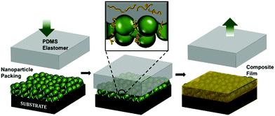
To illustrate LeCaRI, we use a commonly used elastomer made of poly(dimethylsiloxane) (PDMS). The most widely used form of the PDMS elastomer, SYLGARD™ 184, is made of vinyl terminated PDMS chains. By inducing crosslinking between the PDMS chains, a monolithic PDMS elastomer can be prepared. Prior publications have reported that during the curing of PDMS elastomer, not all oligomers in the mixture get incorporated into the network.46 Rather, in a single piece of PDMS elastomer, a large number of un-crosslinked PDMS oligomeric chains are present. These uncross-linked chains have been removed using different methods.46–51 Although the presence of these uncrosslinked oligomers is often regarded as an undesirable nuisance, we take advantage of the fact that these oligomers have high mobility and that they can be leached out of the network. The presence of uncross-linked chains in the PDMS elastomer and their ability to leach out make PDMS an invaluable reservoir of oligomers that can be infiltrated into a NP packing by LeCaRI as illustrated in Scheme 1.LeCaRI is demonstrated by inducing infiltration of oligomeric PDMS into films of randomly packed silica (SiO2) NPs. A 250 nm thick film of 27 nm SiO2 NP is prepared using spin coating. A slab of PDMS (1 × 1 × 0.5 cm3) is then brought into conformal contact with the top of the NP film and held in place for 5–10 seconds as shown in Scheme 1. The PDMS is then detached from the NP film slowly. The refractive index of the NP film, as measured by ellipsometry, increases indicating the infiltration of oligomeric species into the voids of the NP packing. Oligomer infiltration is further confirmed by scanning electron microscopy (SEM) of the NP film before and after LeCaRI. The voids of the NP packing appear dense and filled after LeCaRI as shown in Fig. 1. The void spaces between the spherical NPs have been filled with a darker material in the top surface, and the cross-sectional SEM micrograph shows that the NPs are covered with a thin liquid like film made of the infiltrated PDMS oligomers. There is no change in the thickness of the packing after infiltration, indicating that the volume fraction of the packing remains constant above 60 vol%.
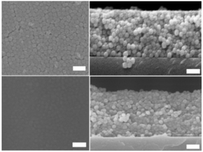 | ||
| Fig. 1 SEM images of the top-down (left) and cross-section (right) of the NP packings before (top) and after (bottom) LeCaRI. All the scale bars represent 100 nm. | ||
To confirm whether it is in fact oligomeric PDMS chains that have infiltrated the SiO2 NP film, we remove the uncross-linked chains from PDMS elastomer before LeCaRI by soaking freshly cured PDMS in a good solvent (toluene)46,50 for a week. The PDMS elastomer shrinks due to the loss of the oligomers and loses its weight by 4.5 wt%. The elastomer is subsequently, soaked in ethanol for a day to make it more flexible. When such a PDMS elastomer is brought into conformal contact with a SiO2 NP film, there is no change in the refractive index of the NP film, which indicates that LeCaRI has not taken place. Thus, the presence of uncross-linked and thus mobile chains in the PDMS elastomer is an important criterion for LeCaRI to occur.
Monitoring the kinetics of the infiltration process shows that the LeCaRI process is extremely fast. Complete infiltration is achieved within 5–10 seconds of establishing conformal contact between the NP film and the PDMS elastomer as shown in ESI.† If the time of infiltration is estimated based on the Lucas–Washburn model, which has successfully described capillary rise of polymers in nanoconfined pores,1,6,7,52–54 it would indeed take less than 1 s for complete infiltration to occur (see ESI,† for details).
We believe there are two important factors that control the extent of oligomer infiltration (i.e., volume fraction of oligomers): NP size and relative humidity. The capillary pressure that induces LeCaRI is inversely proportional to the NP size. It is also well known that water vapor undergoes capillary condensation in these NP packings. This water exists in the narrow necks between adjoining NPs forming liquid bridges.4,55 The high curvature of the liquid/vapor interface of the liquid bridge between NPs leads to a depressed vapor pressure of the condensate liquid. Increased relative humidity results in greater amount of capillary condensed water.
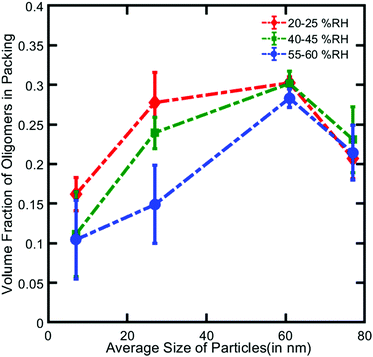
To study the effects of NP size and relative humidity on the extent of LeCaRI, SiO2 NPs of various average sizes ranging from 7 to 77 nm are used to prepare NP films, which are subsequently exposed to three different levels of relative humidity: 20–25 RH% under ambient conditions, and 40–45 RH% and 55–60 RH% in a humidity-controlled chamber. PDMS elastomer is brought into conformal contact with each NP film and left in contact for 5–10 seconds. Comparing the change in the refractive index values before and after LeCaRI enables calculation of the volume of oligomers in the packing as summarized in Fig. 2 (details of calculation are provided in ESI†).
Two general trends are observed. For a constant particle size, the amount of oligomers inside the packing decreases with the increase in the humidity level likely due to a greater amount of capillary condensed water in the packing. This decrease is starkly evident in the NP packings with small SiO2 NPs (7 nm and 27 nm) in which the amount of capillary-condensed water is higher compared to that in the packings with larger SiO2 NPs (i.e., 61 nm and 77 nm). Increasing humidity therefore decreases the void volume available for infiltration and decreases the oligomer fraction in the packing.
For a given relative humidity, we observe a maximum in the extent of oligomer infiltration at the particle size of 61 nm. This non-monotonic dependence can be explained by considering the two opposing factors: the driving force for LeCaRI and the tendency of water vapor to undergo capillary condensation. The NP size primarily controls the driving force of LeCaRI (∼1/r, where r is the size of NP). Capillary force that drives LeCaRI is very strong in the small sized NP packings where the void sizes are proportionately smaller. Thus, in the absence of capillary condensed water, the packing with the smallest particle size would induce the largest extent of LeCaRI. For a value of RH that is greater than 0%, however, the particle size determines the amount of capillary condensed water that resides within the packing before LeCaRI takes place.55 At room temperature and humidity (18–22 °C and 20–25% RH in our experiments), for example, packings of 7 nm and 27 nm diameter NP have 15% and 10%, respectively, of their void volume filled with water due to capillary condensation (see ESI,† for detailed description on how the amount of water was determined). Smaller NPs induce higher degree of water vapor condensation. This trend means that the larger particle packings have more void volume available for infiltration than the smaller particle packings. Therefore, these two factors – driving force for LeCaRI and the amount of capillary-condensed water – show opposing trends with particle size at a constant humidity value. We believe this trade-off leads to a maximum in the oligomer content at an intermediate particle size of 61 nm. In the case of 7 nm packing, the driving force is high but the pores are occupied heavily by capillary condensed water, whereas in the 77 nm packing, there is more void volume available for the infiltration of oligomers but the driving force for LeCaRI is weak. These results demonstrate that the amount of oligomers infiltrated in the SiO2 NP films can be varied by adjusting the relative humidity and NP size at room temperature.
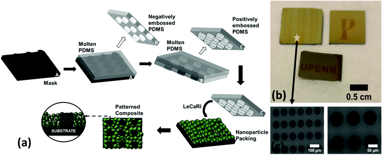
LeCaRI is a rapid, simple, and potentially scalable route to the manufacturing of PINFs. One important advantage of using PDMS elastomer is that the PDMS can be patterned to have micron-sized surface features. Soft lithography has been widely used to enable microcontact printing and patterning on planar surfaces.56–59 We take advantage of this versatility of PDMS to induce localized LeCaRI to produce patterned PINFs. A patterned PDMS stamp is prepared using the common soft lithography technique. PDMS precursor is poured onto a hard master that has surface features. PDMS is subsequently cured and peeled from the master and used to make a patterned PDMS stamp as schematically illustrated in Fig. 3a. We use a PDMS stamp with cylindrical pillars of 60 μm radius and 100 μm height with 30 μm inter-pillar distance to induce infiltration into circular regions in 27 nm-SiO2 NP films with a thickness of 250 nm. Patterned regions can be clearly observed to the naked eye due to the difference in the refractive indices of the infiltrated and neat NP packings (Fig. 3b). The feature size imprinted on the NP films are comparable to the size of the patterns on the PDMS elastomers as seen in Fig. 3c and d.
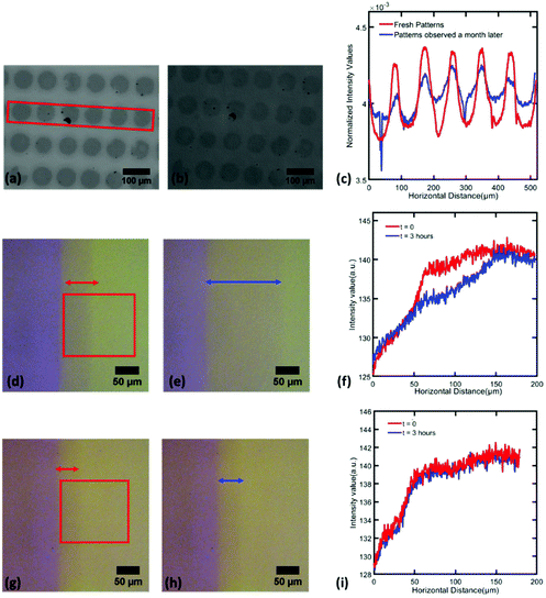
PDMS oligomers that infiltrate into NP packings in LeCaRI are low molecular weight species and are therefore highly mobile. Thermal energy is sufficient to induce diffusion of the oligomer chains, and this motion is expected to occur even within the NP packing after LeCaRI at room temperature. The mobility of these oligomers can be directly observed by monitoring freshly prepared circular patterns over a period of one month. As shown in Fig. 4, the patterns fade over time and the contrast difference between the infiltrated and the originally uninfiltrated regions decreases with time as seen in Fig. 4c which shows the average grayscale intensity of pixels in a rectangular region drawn around the patterns for freshly made samples (red) and samples observed a month later (blue).
The contrast in the intensities of patterned region seen in the red curve are reduced in the blue curve (Fig. 4c) indicating lateral spreading of the oligomer over time. Patterns which spread out and fade away over time offer potential applications in making self-destructive patterns with coded messages that can vanish away with time. Another promising application is in the manufacture of patterned surfaces with a graded wetting properties which has been previously been realized by using topographic features on surfaces.32,55 LeCaRI enables room-temperature and solvent-free fabrication of patterned regions with a gradient in wetting without using any tedious or costly micro-patterning techniques.
Although spreading of infiltrated oligomers can provide advantages for some applications, it could also be desirable to permanently fix the freshly prepared or laterally graded patterns for other applications. To demonstrate that patterns can be permanently localized, we use a variant of commercial PDMS that can be crosslinked under ultraviolet (UV) irradiation. This UV-crosslinkable PDMS (UV-PDMS) is incorporated into the PDMS elastomer by simply adding it to the precursor prior to thermal curing (see ESI,† for details). UV-PDMS is subsequently induced to undergo LeCaRI, leaching out of the PDMS elastomer and into the voids in a 27 nm-SiO2 NP film with a thickness of 250 nm.
When patterning is performed using UV-PDMS, a region with intermediate light intensity between the infiltrated (purple region) and uninfiltrated (dull yellow) regions is observed close to the edge of the pattern (blue arrow in Fig. 4d). This intermediate region indicates that there is an immediate lateral spreading of the oligomer upon performing LeCaRI. The width of this middle region increases with time as indicated by the red arrow in Fig. 4e as well as the intensity profile in Fig. 4f. The spreading front moves approximately 80 μm in distance in 3 hours. When the patterned LeCaRI film is irradiated with UV upon producing the pattern via LeCaRI, no spreading of this intermediate region is observed as observed in Fig. 4g–i, due to the crosslinking of UV-PDMS oligomers inside the NP film; the crosslinked UV-PDMS loses the mobility to undergo spreading. Thus, the patterns can be permanently locked into the original regions where LeCaRI has taken place. In addition, LeCaRI potentially could enable the removal of un-infiltrated NP packings to produce patterns of highly filled composite materials on the surface. The feasibility of such a patterning method likely will depend on the interplay of particle–particle, particle–polymer, polymer–substrate and NP–substrate interactions.
Conclusions and outlook
In conclusion, we have presented a powerful and rapid method to induce infiltration of oligomeric species from PDMS elastomer into NP films, which can be used to pattern PINFs. The entire process is completed in a matter of seconds at room temperature without the need for solvents. Because of the simplicity and rapidity of the process, there is immense possibilities in up-scaling this method to enable scalable manufacturing of patterned PINFs. LeCaRI films have high fill fractions of NPs and the extent of oligomer infiltration can be controlled by varying the humidity of the surroundings and the NP size. The patterns of PINFs prepared using PDMS spread over time giving lateral gradients in compositions. The patterns can also be locked in permanently by inducing crosslinking of infiltrated oligomers, which we demonstrate using light-activated crosslinking. The incorporation and subsequent infiltration of UV-PDMS suggests that LeCaRI can potentially be used with other species that can be incorporated in PDMS or other types of elastomeric network (e.g., polyurethane), making it a general method of patterning PINFs with low glass transition temperature polymers. Our on-going work focuses on testing different pairs of polymers and NPs to establish an understanding of how polymer–NP interactions would affect LeCaRI.There are multiple fundamental questions as well as interesting avenues for further extension and development of this work. The lateral spreading of oligomers provides a powerful platform to study the transport phenomena in nanoporous structure with high degrees of confinement. By infusing PDMS elastomers with monodisperse PDMS chains, it will be possible to study the impact of confinement on the dynamics of PDMS by simply following the spreading of patterns using optical microscopy. Technologically, the laterally patterned and graded regions can be engineered to have properties desired for applications in water management, microsensors, photonic and optical applications.
Conflicts of interest
There are no conflict of interests to declare.Acknowledgements
This work was supported by Penn MRSEC (DMR 1720530). We thank Dr Xu A. Zhang for his inputs on UV-PDMS and its curing process.Notes and references
- Y. R. Huang, Y. Jiang, J. L. Hor, R. Gupta, L. Zhang, K. J. Stebe, G. Feng, K. T. Turner and D. Lee, Nanoscale, 2015, 7, 798–805 RSC.
- K. M. Coakley, Y. Liu, M. D. McGehee, K. L. Frindell and G. D. Stucky, Adv. Funct. Mater., 2003, 13, 301–306 CrossRef CAS.
- W. Chen, L. Qu, D. Chang, L. Dai, S. Ganguli and A. Roy, Chem. Commun., 2008, 163–165 RSC.
- N. Manohar, K. J. Stebe and D. Lee, ACS Macro Lett., 2017, 6, 1104–1108 CrossRef CAS.
- Y. Qiang, N. Manohar, K. J. Stebe and D. Lee, Mol. Syst. Des. Eng., 2018, 3, 96–102 RSC.
- J. L. Hor, Y. Jiang, D. J. Ring, R. A. Riggleman, K. T. Turner and D. Lee, ACS Nano, 2017, 11, 3229–3236 CrossRef CAS PubMed.
- P. E. de Jongh and T. M. Eggenhuisen, Adv. Mater., 2013, 25, 6672–6690 CrossRef CAS PubMed.
- Y. Jiang, J. L. Hor, D. Lee and K. T. Turner, ACS Appl. Mater. Interfaces, 2018, 10, 44011–44017 CrossRef CAS PubMed.
- S. Sen, J. D. Thomin, S. K. Kumar and P. Keblinski, Macromolecules, 2007, 40, 4059–4067 CrossRef CAS.
- Q. Chen, S. Gong, J. Moll, D. Zhao, S. K. Kumar and R. H. Colby, ACS Macro Lett., 2015, 4, 398–402 CrossRef CAS.
- U. G. Wegst, H. Bai, E. Saiz, A. P. Tomsia and R. O. Ritchie, Nat. Mater., 2015, 14, 23–36 CrossRef CAS PubMed.
- E. Munch, M. E. Launey, D. H. Alsem, E. Saiz, A. P. Tomsia and R. O. Ritchie, Science, 2008, 322, 1516–1520 CrossRef CAS PubMed.
- F. Flory, L. Escoubas and G. Berginc, J. Nanophotonics, 2011, 5, 052502 CrossRef.
- M. R. Bockstaller and E. L. Thomas, J. Phys. Chem. B, 2003, 107, 10017–10024 CrossRef CAS.
- J. Zhang, N. Coombs and E. Kumacheva, J. Am. Chem. Soc., 2002, 124, 14512–14513 CrossRef CAS PubMed.
- Y. Y. Li, V. S. Kollengode and M. J. Sailor, Adv. Mater., 2005, 17, 1249–1251 CrossRef CAS.
- T. C. Merkel, B. D. Freeman, R. J. Spontak, Z. He, I. Pinnau, P. Meakin and A. J. Hill, Science, 2002, 296, 519–522 CrossRef CAS PubMed.
- M. B. Shiflett and H. C. Foley, Science, 1999, 285, 1902–1905 CrossRef CAS PubMed.
- S. M. Liff, N. Kumar and G. H. McKinley, Nat. Mater., 2007, 6, 76–83 CrossRef CAS PubMed.
- S. Cheng and G. S. Grest, ACS Macro Lett., 2016, 5, 694–698 CrossRef CAS.
- S. K. Kumar, N. Jouault, B. Benicewicz and T. Neely, Macromolecules, 2013, 46, 3199–3214 CrossRef CAS.
- P. Akcora, H. Liu, S. K. Kumar, J. Moll, Y. Li, B. C. Benicewicz, L. S. Schadler, D. Acehan, A. Z. Panagiotopoulos, V. Pryamitsyn, V. Ganesan, J. Ilavsky, P. Thiyagarajan and R. H. Colby, Nat. Mater., 2009, 8, 354–359 CrossRef CAS PubMed.
- M. E. Mackay, A. Tuteja, P. M. Duxbury, C. J. Hawker, B. Van Horn, Z. Guan, G. Chen and R. S. Krishnan, Science, 2006, 311, 1740–1743 CrossRef CAS PubMed.
- M. Li, H. Tan, L. Chen, J. Wang and S. Y. Chou, J. Vac. Sci. Technol., B: Microelectron. Nanometer Struct.–Process., Meas., Phenom., 2003, 21, 660–663 CrossRef CAS.
- M. Deutsch, Y. A. Vlasov and D. J. Norris, Adv. Mater., 2000, 12, 1176–1180 CrossRef CAS.
- S. O. Kim, H. H. Solak, M. P. Stoykovich, N. J. Ferrier, J. J. de Pablo and P. F. Nealey, Nature, 2003, 424, 411–414 CrossRef CAS PubMed.
- D. P. Song, C. Li, W. Li and J. J. Watkins, ACS Nano, 2016, 10, 1216–1223 CrossRef CAS PubMed.
- L. Yao and J. J. Watkins, ACS Nano, 2013, 7, 1513–1523 CrossRef CAS PubMed.
- M. Kim and J. Noh, Micromachines, 2018, 9, 208 CrossRef PubMed.
- A. Y. Vorobyev and C. Guo, J. Appl. Phys., 2015, 117, 033103 CrossRef.
- E. Ueda and P. A. Levkin, in Non-wettable surfaces: theory, preparation and applications, ed. R. H. A. Ras and A. Marmur, Royal Society of Chemistry, Cambridge, 2016, ch. 7, pp. 182–222 Search PubMed.
- Y. Xing, W. Shang, Q. Wang, S. Feng, Y. Hou and Y. Zheng, ACS Appl. Mater. Interfaces, 2019, 11, 10951–10958 CrossRef CAS PubMed.
- F. Chen, W. Xu, Y. Lu, J. Song, S. Huang, L. Wang, I. P. Parkin and X. Liu, Micro Nano Lett., 2015, 10, 105–108 CrossRef CAS.
- M. Kuang, J. Wang, B. Bao, F. Li, L. Wang, L. Jiang and Y. Song, Adv. Opt. Mater., 2014, 2, 34–38 CrossRef.
- J. K. Hwang, S. Cho, J. M. Dang, E. B. Kwak, K. Song, J. Moon and M. M. Sung, Nat. Nanotechnol., 2010, 5, 742–748 CrossRef CAS PubMed.
- R. Kothari, M. R. Beaulieu, N. R. Hendricks, S. Li and J. J. Watkins, Chem. Mater., 2017, 29, 3908–3918 CrossRef CAS.
- W. S. Kim, K. B. Yoon and B. S. Bae, J. Mater. Chem., 2005, 15, 4535–4539 RSC.
- J. John, Y. Tang, J. P. Rothstein, J. J. Watkins and K. R. Carter, Nanotechnology, 2013, 24, 505307 CrossRef PubMed.
- M. J. Hampton, S. S. Williams, Z. Zhou, J. Nunes, D. H. Ko, J. L. Templeton, E. T. Samulski and J. M. DeSimone, Adv. Mater., 2008, 20, 2667–2673 CrossRef CAS PubMed.
- P. Yang, T. Deng, D. Zhao, P. Feng, D. Pine, B. F. Chmelka, G. M. Whitesides and G. D. Stucky, Science, 1998, 282, 2244–2246 CrossRef CAS PubMed.
- S. H. Ko, I. Park, H. Pan, C. P. Grigoropoulos, A. P. Pisano, C. K. Luscombe and J. M. Fréchet, Nano Lett., 2007, 7, 1869–1877 CrossRef CAS PubMed.
- W. Li, Y. Zhou, I. R. Howell, Y. Gai, A. R. Naik, S. Li, K. R. Carter and J. J. Watkins, ACS Appl. Mater. Interfaces, 2018, 10, 5447–5454 CrossRef CAS PubMed.
- S. Nagarajan, T. P. Russell and J. J. Watkins, Adv. Funct. Mater., 2009, 19, 2728–2734 CrossRef CAS.
- X. Liu, N. Bhandaru, M. Banik, X. Wang, A. M. Al-Enizi, A. Karim and R. Mukherjee, ACS Omega, 2018, 3, 2161–2168 CrossRef CAS.
- M. Geissler and Y. Xia, Adv. Mater., 2004, 16, 1249–1269 CrossRef CAS.
- A. Hourlier-Fargette, J. Dervaux, A. Antkowiak and S. Neukirch, Langmuir, 2018, 34, 12244–12250 CrossRef CAS PubMed.
- S. Yunus, C. D. De Looringhe, C. Poleunis and A. Delcorte, Surf. Interface Anal., 2007, 39, 922–925 CrossRef CAS.
- K. J. Regehr, M. Domenech, J. T. Koepsel, K. C. Carver, S. J. Ellison-Zelski, W. L. Murphy, L. A. Schuler, E. T. Alarid and D. J. Beebe, Lab Chip, 2009, 9, 2132–2139 RSC.
- E. Berthier, E. W. Young and D. Beebe, Lab Chip, 2012, 12, 1224–1237 RSC.
- J. N. Lee, C. Park and G. M. Whitesides, Anal. Chem., 2003, 75, 6544–6554 CrossRef CAS PubMed.
- L. Millet, A. Jain and M. Gillette, bioRxiv, 2017 DOI:10.1101/150953.
- E. Kim, Y. Xia and G. M. Whitesides, Nature, 1995, 376, 581–584 CrossRef CAS.
- B. Y. Cao, M. Yang and G. J. Hu, RSC Adv., 2016, 6, 7553–7559 RSC.
- M. Zhang, P. Dobriyal, J. T. Chen, T. P. Russell, J. Olmo and A. Merry, Nano Lett., 2006, 6, 1075–1079 CrossRef CAS.
- Z. Gemici, P. I. Schwachulla, E. H. Williamson, M. F. Rubner and R. E. Cohen, Nano Lett., 2009, 9, 1064–1070 CrossRef CAS PubMed.
- S. A. Ruiz and C. S. Chen, Soft Matter, 2007, 3, 168–177 RSC.
- Y. Xia and G. M. Whitesides, Angew. Chem., 1998, 37, 550–575 CrossRef CAS.
- K. E. Paul, M. Prentiss and G. M. Whitesides, Adv. Funct. Mater., 2003, 13, 259–263 CrossRef CAS.
- J. Zhao and S. Chen, Langmuir, 2017, 33, 5328–5335 CrossRef CAS PubMed.
Footnote |
| † Electronic supplementary information (ESI) available. See DOI: 10.1039/c9nh00130a |
| This journal is © The Royal Society of Chemistry 2019 |

