
Site-specific Ag coating on concave Au nanoarrows by controlling the surfactant concentration†
Dashen
Dong
 ab,
Qianqian
Shi
ab,
Debabrata
Sikdar
c,
Yunmeng
Zhao
ab,
Yiyi
Liu
ab,
Runfang
Fu
ab,
Malin
Premaratne
d and
Wenlong
Cheng
*ab
ab,
Qianqian
Shi
ab,
Debabrata
Sikdar
c,
Yunmeng
Zhao
ab,
Yiyi
Liu
ab,
Runfang
Fu
ab,
Malin
Premaratne
d and
Wenlong
Cheng
*ab
aDepartment of Chemical Engineering, Monash University, Clayton 3800, Victoria, Australia. E-mail: wenlong.cheng@monash.edu
bThe Melbourne Centre for Nanofabrication, 151 Wellington Road, Clayton 3168, Victoria, Australia
cDepartment of Electronics and Electrical Engineering, Indian Institute of Technology Guwahati, Guwahati 781039, India
dAdvanced Computing and Simulation Laboratory (AχL), Department of Electrical and Computer Systems Engineering, Monash University, Clayton 3800, Victoria, Australia
First published on 19th February 2019
Abstract
The ability to control the site-selective deposition of a noble metal with nanoscale accuracy is vital for the synthesis of well-defined heterogeneous core-shell bimetallic nanoparticles for various applications ranging from nanophotonics to catalysis. Here, precise site-specific Ag coating onto concave gold nanoarrows (GNAs) is reported by tuning the concentration of the surfactant – cetyltrimethylammonium chloride (CTAC). Three distinct nanocoating structures, namely, anisotropic coating, middle coating, and conformal coating are obtained, which are achieved under low, medium and high CTAC concentrations, respectively. The site-specific nanoscale coating on GNAs is proved by scanning transmission electron microscopy imaging in conjunction with the elemental mapping. The CTAC concentration-dependent, facet-specific passivation may be the cause for the three distinct nanoparticles obtained. The morphology differences resulted in discrete plasmonic features, and a linear relationship between the resonance peak and the CTAC concentration is found for the conformal-coated GNAs. We further fabricate free-standing monolayer nanosheets out of the three kinds of nanoparticles, which display strong shape-dependent SERS enhancements.
Conceptual insightsPrecise site-specific Ag coating onto concave gold nanoarrows is demonstrated by virtue of fine-tuning the concentration of the surfactant – cetyltrimethylammonium chloride (CTAC). This enables anisotropic coating, middle coating, and conformal coating, as experimentally proved by scanning transmission electron microscopy imaging in conjunction with the elemental mapping and plasmonic profiles. Using the three kinds of nanoparticles obtained, we fabricate free-standing monolayered nanosheets with SERS enhancements highly dependent on the structures of the constituent building blocks. Our strategies represent a novel route to synthesize well-defined heterogeneous core–shell bimetallic nanoparticles for a myriad of potential applications in next-generation optoelectronics. |
Introduction
Metal nanocrystals have received considerable attention, which stems not only from their tiny structures but also from their size- and shape-dependent properties. Among these, plasmonic bimetallic nanoparticles (e.g. core–shell particles) attract particular interests due to their tailorable localized surface plasmon resonance (LSPR) and wide applications in the field of photonics,1,2 catalysis,3,4 biochemical sensing5–7 and anticounterfeiting.8 For many of these applications, it is important to control the LSPR properties of the core–shell particles, which strongly depend on their sizes and shapes as well as the relative thickness.9–11 Hence, the ability to precisely control the structures of core–shell nanoparticles is crucial for plasmon-enabled applications.Past decades have witnessed intensive research efforts to synthesize structurally well-defined bimetallic nanoparticles by controlling various parameters of seed-mediated growth. The types and amount of precursors added were found to relate to the asymmetric structures of core–shell nanocrystals.12,13 By adjusting the pH, the deposition could also be controlled on either end or in the middle of elongated particles.14 Dendritic nanocrystals could be obtained through a co-reduction process where the surface diffusion was slowed down by controlling the relative amount of reducing agents.15–18 Besides, templates, such as silica, were used as a protective layer to ensure site-specific growth on the exposed particle surfaces, leading to asymmetric bimetallic particles.19–21 Capping agents were recently found to play key roles in shape control because of their facet-specific binding properties. For example, the controlled deposition of Ag on Pd nanocubes was achieved by using poly(vinyl pyrrolidone).22
Here, we report a highly efficient surfactant-based approach to site-specifically control Ag coating on concave gold nanoarrows (GNAs) simply by tuning the concentration of cetyltrimethylammonium chloride (CTAC). Under a low CTAC concentration, Ag deposition on GNA was non-uniform, leading to a cuboid-shaped shell, which is termed anisotropic coating (ac-GNA); when the CTAC concentration is in the middle range, Ag would selectively deposit onto the concave part of the GNA, which is termed selective middle coating (mc-GNA); at a high CTAC concentration, Ag would deposit conformally across the entire surface of GNA, which is termed conformal coating (cc-GNA). The three distinct coating structures were confirmed by high-resolution electron microscopy in conjunction with elemental mapping, and are also in excellent agreement with the characteristic plasmonic resonance spectra observed. CTAC concentration-dependent, facet-specific passivation may be the cause of the site-specific Ag deposition described above. We further fabricated nanosheets using our two-step drying-mediated self-assembly,23 which exhibited strong coating-dependent surface enhanced Raman scattering (SERS).
Results and discussion
GNAs are a kind of anisotropic nanoparticle composed of two pyramid heads and a four-wing shaft. ∼120 nm GNAs have been reported previously,24 which have been shown to exhibit interlocking packing due to a concave geometry. We modified the synthesis process and successfully obtained GNAs of ∼60 nm. In brief, a short gold nanorod (∼50 nm length) was first obtained through a 2-hour seed-mediated growth,25 then a growth solution was added to yield the concave GNA.24 The resonance shift and solution color change were consistent with reported literature, which indicates the successful synthesis of GNAs (Fig. S1, ESI†). Experimental details can be found in the Experimental section.To deposit Ag onto the GNAs, the GNA particles were first re-dispersed in CTAC solutions with three different concentrations (80, 378 and 600 mM). Then, AgNO3 and ascorbic acid were added in sequence under constant stirring in a 60 °C water bath. The reaction was kept for 4 hours. This process led to the reduction of silver ions and consequent deposition on the GNA surfaces. To fully understand how the surfactants influenced the silver coating, all other experimental conditions were identical except for varying the surfactant concentration.
The coating of Ag onto GNA was carefully characterized by electron microscopy. Transmission electron microscopy (TEM) images of Ag coated GNA show that the Ag coating process was highly dependent on the CTAC concentration (Fig. 1a). The cuboid-shaped nanoparticles, nanoarrows with smooth surface in the middle and nanoarrows with concave surface in the middle were clearly observed for low, middle and high concentration of CTAC. All of these particles turned out to be single crystals as demonstrated from the selective area electron diffraction (SAED) pattern (Fig. S2, ESI†). These SAED patterns matched well with face-centered-cubic silver.
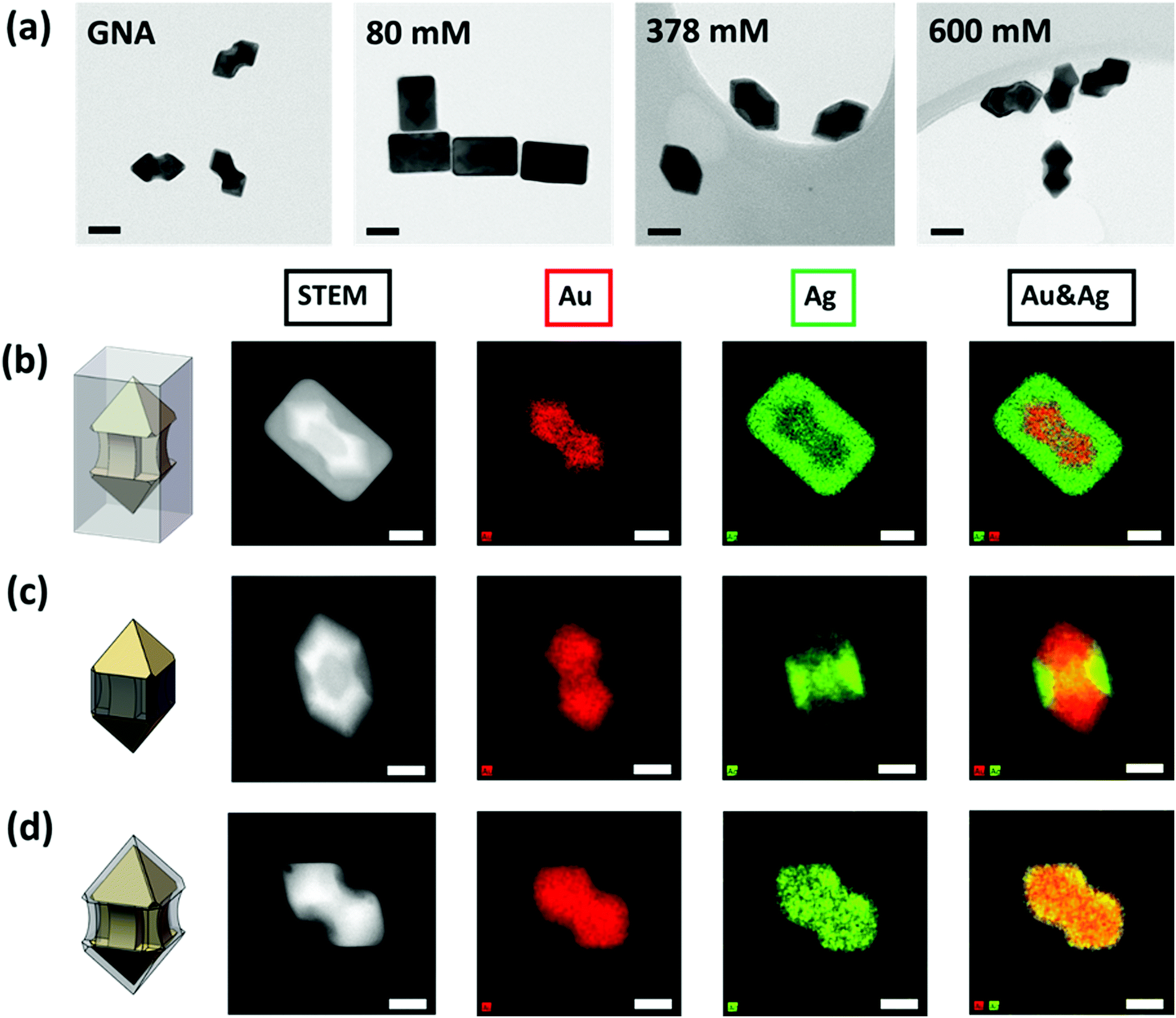 | ||
| Fig. 1 (a) TEM images of GNAs and Ag coated GNAs under different CTAC concentration. Scale bar is 40 nm. (b-d) STEM-HAADF images and elemental maps of the corresponding Ag coated GNAs: (b) ac-GNAs, (c) mc-GNAs and (d) cc-GNAs. Scale bar is 20 nm. | ||
To further reveal where silver coating occurred, we conducted a characterization using STEM-HAADF (high-angle annular dark-field) and STEM-EDS (energy-dispersive X-ray spectroscopy). Fig. 1b–d presents the STEM-HAADF images and their corresponding elemental maps. Good contrast of the Au core and Ag shell components could be clearly seen on all the HAADF images and the EDS maps gave the distribution information of Au and Ag elements. Under low CTAC concentration, the GNA core was fully covered with cuboid shaped Ag shell. Because the coating was not uniform across the GNA surface, it was termed as ac-GNA to reflect the anisotropic-coated GNA (Fig. 1b). When the CTAC concentration was in the middle range, most of the Ag element was deposited on the middle shaft rather than the two pyramid heads of the GNA and these middle coating only nanoparticles were called mc-GNAs (Fig. 1c). When the CTAC concentration was high, a continuous conformal Ag layer was found across the GNA surface, which was termed as conformally coated GNA (cc-GNA), as shown in Fig. 1d. The three distinct Ag coatings on the GNAs were highly reproducible and could be seen in a large-scale elemental mapping as shown in Fig. S3 (ESI†).
Corresponding to the three distinct particle structures, we observed the corresponding optical properties. A yellow, red and dark purple solution was obtained for 80 mM, 378 mM and 600 mM CTAC, respectively (Fig. 2a), which refers to ac-GNA, mc-GNA and cc-GNA. Corresponding to these visual colors, three distinct plasmonic spectra were observed, as shown in Fig. 2b. For the GNA solution, there were two resonance peaks located at 539 nm and 666 nm, corresponding to the dipolar transverse and longitudinal modes, respectively. For ac-GNA (80 mM CTAC), there were four resonance peaks, the two on the left corresponding to the longitudinal and transverse dipolar plasmon modes, while the two on the right were attributed to the octupolar modes, which is similar to the Au@Ag cuboid shell particles.26 For mc-GNA (378 mM CTAC), we also found four resonance peaks. In comparison with the cuboid shell one, there was an obvious red shift for the transverse dipolar mode, which was due to less Ag deposition, in excellent agreement with the TEM and elemental mapping results (Fig. 1c). Consistently, the absence of silver deposition in the GNA pyramid ends led to a slight longitudinal dipolar mode blue shift. This was also in agreement with the electric-field distribution as shown in Fig. 2c. As for the cc-GNAs (600 mM CTAC), the line shape resembled that for the original GNAs except for the two resonance peaks blue shifting to ∼516 nm and ∼582 nm. Simultaneously, an additional peak at 343 nm was observed. This correlates very well with the thin conformal Ag coating on the GNAs (Fig. 1d). We also carried out a simulation study to trace the spectral changes with different silver coatings onto GNAs (Fig. 2d). Here, to make simulations less computationally expensive, we built simulation models based on a few simplifying assumptions; they possess symmetry (Fig. S4, ESI†), whereas samples are more complex geometrically. Nevertheless, qualitatively our models produce results exhibiting trends similar to those seen from experiments.
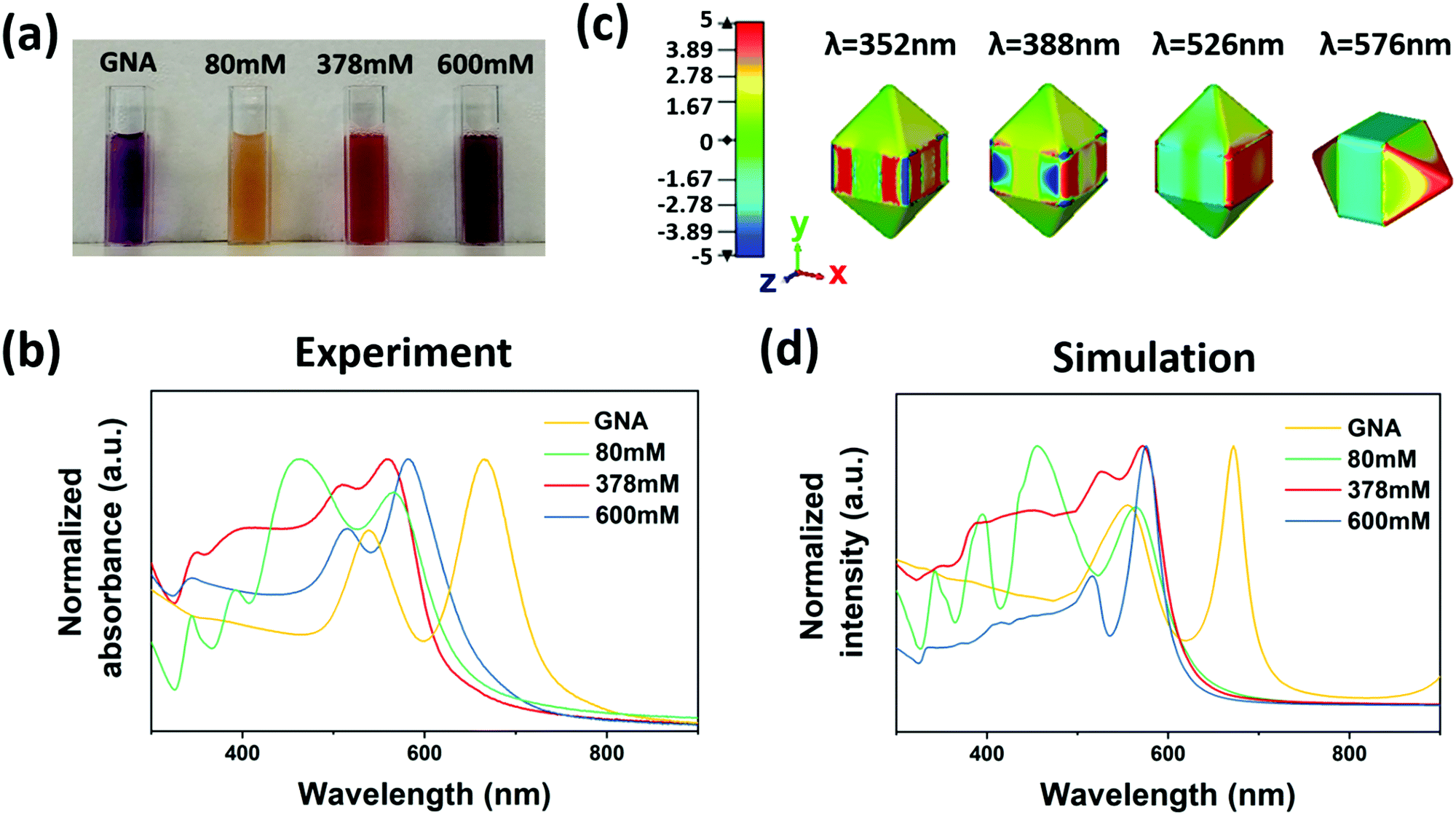 | ||
| Fig. 2 (a) A digital photograph of samples of colloidal solution. The samples from left to right correspond to GNAs, ac-GNAs, mc-GNAs, and cc-GNA, which were grown with increased CTAC concentration. (b) Normalized UV-visible spectra of GNAs, ac-GNAs, mc-GNAs and cc-GNAs. (c) Electric-field distribution (x component) for mc-GNAs depicting different modes from low to high energy (right to left). (d) Corresponding simulated spectra for GNAs, ac-GNAs, mc-GNAs and cc-GNAs. | ||
To reveal how CTAC could induce such site-specific coating, we fine-tuned the experimental conditions with eight different CTAC concentrations, from 80 mM to 756 mM. As shown in the TEM images (Fig. S5, ESI†), a transition from homogeneous Ag cuboid shaped shell to heterogeneous concave site-specific Ag deposition could be clearly seen when the CTAC concentration is increased from 80 mM (low) to 378 mM (medium). Since CTAC has no covalent bonding with the nanoparticles, the absorbed CTAC must be in dynamic chemical equilibrium with that present in bulk solution. The more CTAC molecules are present in the bulk solution, the more likely they absorb onto the nanoparticle surfaces. Under 80 mM CTAC, CTAC molecules might loosely pack on the GNA surfaces (Fig. S6 left, ESI†). This enabled the facile penetration of Ag ions and ascorbic acids into the CTAC capping layers. In this condition, the rapid nucleation and growth led to the formation of cuboid-shaped silver, similar to the case of gold nanorods.26 When the CTAC concentration was further increased, CTAC would likely form a denser bilayer on the GNA surface. Different from cetyltrimethylammonium bromide (CTAB),27,28 it has been reported that the CTAC has a similar affinity with Au [111] (pyramid heads of GNA) and [110] (middle shaft of GNA) facets.29 However, due to the curvature effect,30,31 a non-compact bilayer would likely form in the middle shaft of GNA (Fig. S6 middle, ESI†). In this situation, the Ag deposition occurs on the middle concave shaft parts. When the CTAC centration was further increased (high, >500 mM), densely packed layers eventually also formed in the middle concave areas. These conformal densely packed CTAC molecules might form bilayers,32 which shielded the GNA surfaces from the effective access of silver ions and ascorbic acid. Hence, only a thin Ag deposition was possible. Our 1H NMR results also showed significant differences of CTAC mass attached on the freeze-dried GNA surfaces under different concentrations of the CTAC aqueous solution, which supports our argument on the concentration-dependent distribution of CTAC on GNA (Fig. S7, ESI†).
To further prove the above mechanism, we investigated how the CTAC concentration influenced the silver coating in the high concentration regime (>500 mM). The colors of the nanoparticle solutions were found to change from dark red to dark blue when the CTAC concertation was increased from 500 mM to 750 mM (Fig. 3a). The corresponding plasmonic resonance spectra were recorded as shown in Fig. 3b. As expected, all the samples should be cc-GNA with two resonance peaks corresponding to dipolar transverse modes (peak I indicated by the grey color) and dipolar longitudinal modes (peak II indicated by red color). At the higher CTAC concentration, both peaks shifted to the red region, moving closer to the peaks of the original GNAs. Moreover, the small peak that appeared at around 340 nm for the 500 mM CTAC sample gradually disappeared with increased concentration. These phenomena proved our argument that denser CTAC layers will build up around the GNAs making the Ag deposition less favorable. This explained well the gradual disappearance of the characteristic Ag peak at 340 nm and accompanying closer peak matching to the original GNAs. Interestingly, we found a linear relationship between the resonance peak position and the CTAC concentration for both peaks I and II after multiple tests (Fig. 3c and d). The fitting led to the following equation:
| yI = 503.370 + 0.02x | (1) |
| yII = 541.359 + 0.07x | (2) |
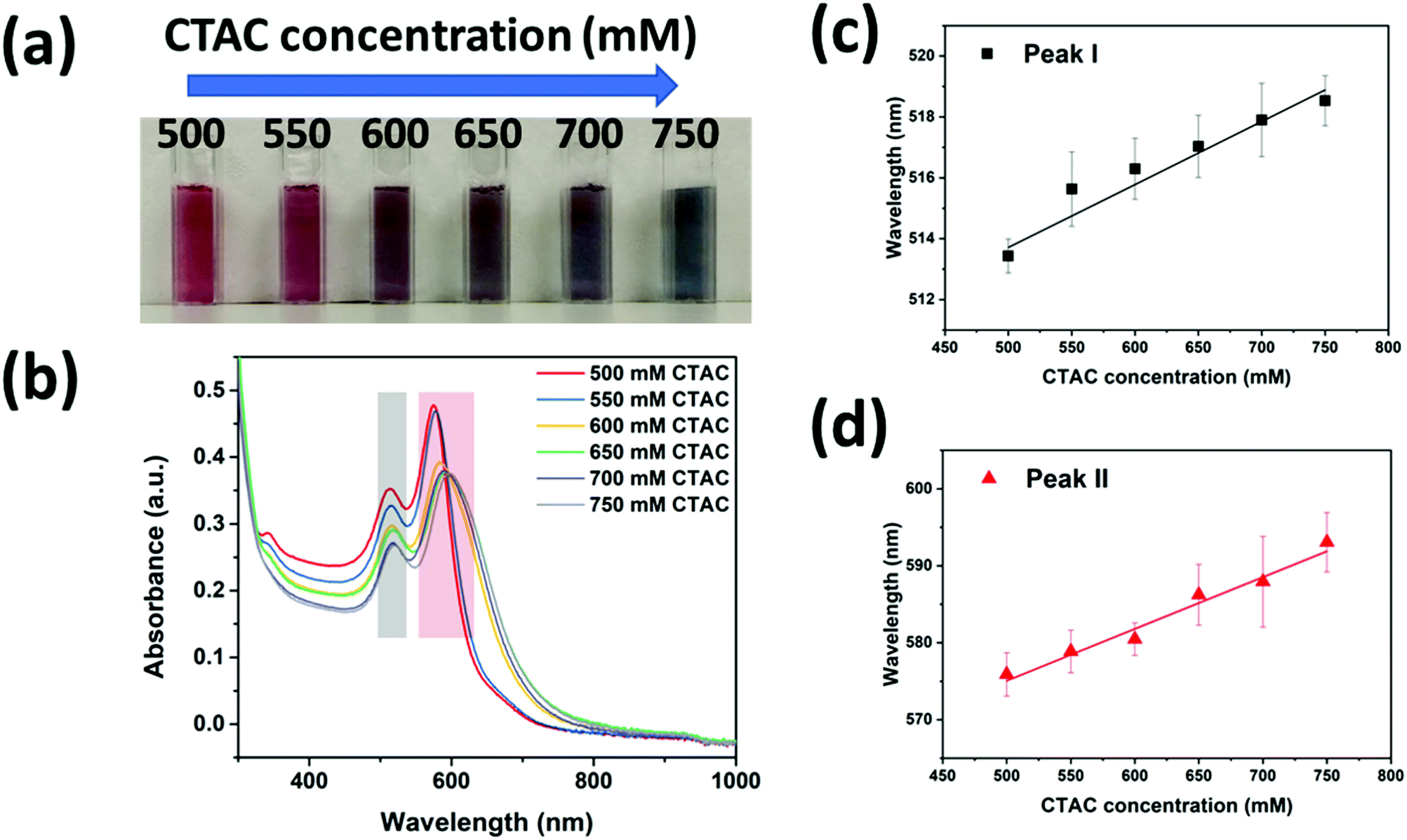 | ||
| Fig. 3 (a) The digital photograph of conformal silver coated GNA colloidal solution. The samples from left to right correspond to those grown with increased CTAC concentration from 500 mM to 750 mM CTAC. (b) UV-visible spectra of cc-GNAs grown under different CTAC concentrations. (c) Dependence of the peak I position on the CTAC concentration. (d) Dependence of the peak II position on the CTAC concentration. | ||
We further used the GNAs, ac-GNAs, mc-GNAs and cc-GNAs as building blocks to fabricate monolayer nanosheets by using our recently developed two-step drying-mediated self-assembly approach.23 After functionalizing the nanoparticles with thiol-terminated polystyrene (PS), they became hydrophobic and could self-assemble at the air–water interface (Fig. S8, ESI†). Upon water evaporation, two-dimensional superlattice nanosheets were obtained on the silicon wafers. The well-ordered horizontal aligned monolayer structure of the nanoparticles could be clearly seen in Fig. 4a–d. The 2D orientational order (S2D) was calculated to be around 0.73, 0.78, and 0.75 respectively for the ac-GNA, mc-GNA and cc-GNA nanosheets after choosing three random regions for each sample (Fig. S9, ESI†). Vertical alignments of those particles within the superlattices were also found in some regions as shown in Fig. S10 (ESI†).
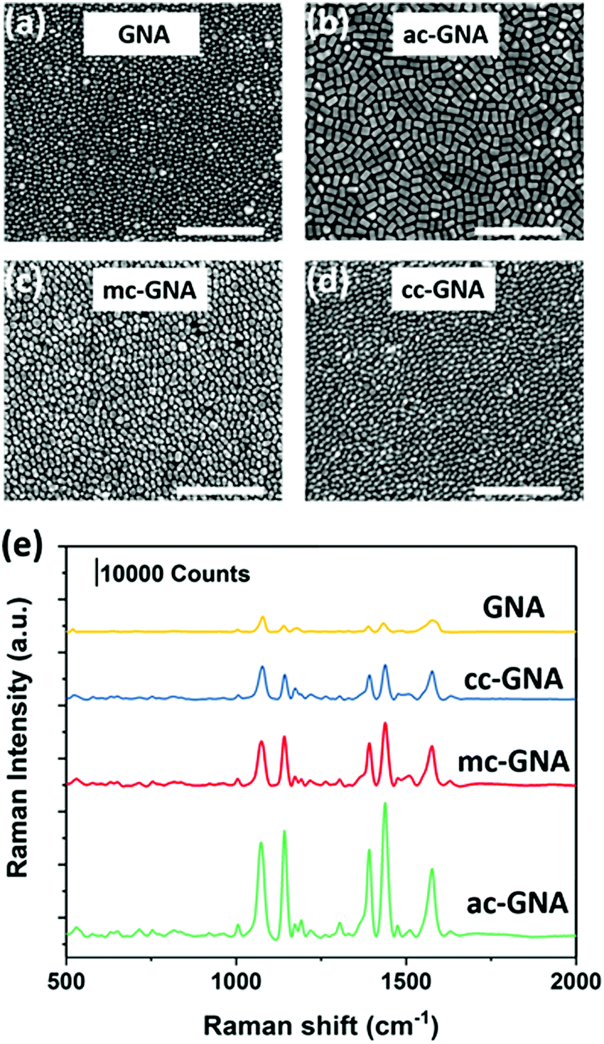 | ||
| Fig. 4 SEM images of self-assembled superlattice nanosheets from (a) GNAs, (b) ac-GNAs, (c) mc-GNAs and (d) cc-GNAs. Scale bar is 500 nm. (e) SERS performance of different nanosheets under 633 nm laser. 4-ATP concentration is 10 μM. | ||
Our previous work has shown that the two-dimensional superlattice nanosheets could serve as a new class of SERS substrate.6,8 Therefore, we investigated the SERS performance of the obtained nanosheets by using 4-aminothiolphenol (4-ATP) as the Raman dye. The nanosheets were first subjected to a short time UV-Ozone treatment and then immersed into a 10 μM 4-ATP ethanol solution. The morphology of the particles was checked before and after treatment to ensure that there was no influence on the structure integrity (Fig. S11, ESI†). Then the nanosheets were placed into a confocal micro-Raman system after being rinsed with ethanol. The excitation laser was chosen as 633 nm which was close to the resonance peak of the fabricated nanosheets33 (Fig. S12, ESI†). As shown in Fig. 4e, the fingerprint peaks of 4-ATP at 1078 and 1578 cm−1 are evident, which are due to the dominated enhancement of a1 vibrational modes, ν(C–S) and ν(C–C), respectively. Among the three Ag-coated nanoparticles, the ac-GNA nanosheet showed the highest Raman intensity, while the cc-GNA showed the lowest intensity. This can be explained by the amount of Ag coated onto the GNA since the extinction coefficient of silver is much higher than that of gold.
Conclusions
In summary, we have developed a reproducible and well-controllable surfactant-based strategy to precisely coat Ag onto gold nanoarrows in a site-specific manner. In particular, we obtained three distinct particles corresponding to anisotropic, middle and conformal coatings. These coating structures were confirmed with electron microscopy in conjunction with elemental mapping, which are also in excellent agreement with the plasmonic spectra as well as simulation results. For cc-GNA, a linear relationship was found between the resonance peak positions and the CTAC concentration. We further fabricated free-standing monolayer nanosheets using the three types of nanoparticles, which could serve as SERS substrates with enhancement factors consistent with the structures of the constituent building blocks. This indicates the potential to design low-cost customizable SERS substrates for a desired chemical analysis.Experimental section
Materials
Gold(III) chloride trihydrate (HAuCl4, ≥99%), hexadecyltrimethylammonium bromide (CTAB, ≥99%), cetyltrimethylammonium chloride (CTAC, 25 wt% in water), sodium borohydride (NaBH4), L-ascorbic acid (AA), 4-amoinothiolphenol (4-ATP), silver nitrate (AgNO3) and indium tin oxide coated glass slides (ITO) were obtained from Sigma-Aldrich. Tetrahydrofuran (THF) and chloroform were purchased from Merck. Hydrochloric acid (HCl, 32%) was from Ajax FineChem. Thiol-terminated polystyrene (Mn = 20![[thin space (1/6-em)]](https://www.rsc.org/images/entities/char_2009.gif) 000 g mol−1) was obtained from Polymer Source Inc. All chemicals were directly used without modification. All glassware was cleaned with freshly prepared Aqua Regia and rinsed thoroughly with Milli-Q water prior to use.
000 g mol−1) was obtained from Polymer Source Inc. All chemicals were directly used without modification. All glassware was cleaned with freshly prepared Aqua Regia and rinsed thoroughly with Milli-Q water prior to use.
Synthesis of the gold nanoarrows
The synthesis of gold nanoarrow (GNA) particles was achieved by following the previous protocols with modifications.24,25 First, gold nanorods were synthesized by a two-step procedure. To obtain the brownish seed solution, 0.05 ml 25 mM HAuCl4 was added into 5 ml 0.1 M CTAB aqueous solution with constant stirring and then 0.3 ml ice-cold NaBH4 was quickly added at room temperature. Then, a growth solution was prepared in a 27 °C water bath by mixing 0.8 ml 4 mM AgNO3, 20 ml 0.2 M CTAB, 20 ml 1 mM HAuCl4 and 320 μl 80 mM AA. Next, 48 μl seed solution was added into the growth solution and kept undisturbed for 2 h. The obtained solution was dark grey in colour and was centrifuged at 7000 rpm for 10 min. The gold nanorod solution was obtained by re-dispersing the precipitate into 1.111 ml Milli-Q water. In the second step, the obtained gold nanorod solution was added into a growth solution containing 668 μl 10 mM HAuCl4, 22.224 ml 0.1 M CTAC, 333.2 μl 10 mM AgNO3, 444 μl 1 M HCl and 333.2 μl 100 mM AA. After proper mixing for 30 s, the solution was left in a 27 °C water bath for 4 hours. After a controlled growth process, the solution colour was changed from dark grey to purple which indicates the successful synthesis of 40 ml GNAs.Site-specific Ag coating onto the gold nanoarrows
Firstly, 10 ml GNAs was centrifuged at 7000 rpm for 10 min and re-dispersed into the same volume of various concentrations of CTAC aqueous solution. Next, the CTAC-capped GNAs were transferred into a glass vial in a 60 °C water bath. Then, Ag coating onto the GNA seeds was started by adding 1300 μl 10 mM AgNO3 and 650 μl 100 mM AA in sequence under constant stirring. After stirring for 4 hours, different kinds of Ag coating onto the gold nanoarrows were obtained.Fabrication of superlattice nanosheets
Our recently developed air–water interface drying-mediated self-assembly approach was used to fabricate the superlattice nanosheets on the holey copper grid/Si wafer/ITO glass.23 As shown in Fig. S8 (ESI†), the first step involves replacing the CTAC ligands with thiolated-polystyrene due to the stronger binding strength. The 10 ml Ag-coated nanoarrow solution was centrifuged at 7000 rpm for 10 min and re-dispersed into 5 ml THF containing 20 mg PS (Mn = 20000 g mol−1). By keeping it undisturbed overnight, the PS ligands were capped onto the nanoparticle surfaces through a ligand exchange process. Then the nanoparticles were washed with THF and chloroform respectively to remove the excess PS polymer through centrifugation and then the final precipitate was dispersed into approximately 15 μl chloroform. In the last step, about 1 μl concentrated particles/chloroform solution was dropped onto the surface of a water droplet on a holey copper grid/Si wafer/ITO glass. Once the water was fully dried, a monolayer two-dimensional superlattice nanosheet was fabricated.
Characterization
The TEM images and SAED pattern were collected using an FEI Tecnai T20 at 200 kV accelerating voltage with a LaB6 filament. The core–shell structure and elemental composition of the Ag-coated nanoarrows were characterized with an FEI Tecnai F20 S/TEM at 200 kV accelerating voltage. An Agilent 8453 UV-vis spectrophotometer was utilized to measure the absorption spectra of the nanoparticles in solution. The morphology and assembled structure of the superlattice nanosheet were observed through the FEI Helios Nanolab 600 FIB-SEM operating at 5 kV. The extinction spectra of the nanosheets were measured using the J&M MSP210 Microscope Spectrometry System with a 20× lens. The SERS spectra were recorded by a Renishaw RM2000 Confocal micro-Raman System with the excitation laser wavelengths of 633 nm, spot size of 1 μm and a laser power of 0.1 mW.Simulation method
The numerical simulations were performed using the frequency-domain solver of the CST Microwave Studio™ Suite to obtain the absorbance spectra over a specified wavelength window as well as the near-field distribution pattern in and around the nanoparticles at a particular wavelength of incident light. Open boundaries were implemented around the target nanoparticle for the incident waves to pass through those boundaries with minimal reflections, emulating perfectly matched layer (PML) boundary conditions. Tetrahedral meshing with adaptive refinement was used for simulations. The relative permittivities of the nanoparticles’ constituent materials were taken from the literature.34 In all the simulations, the nanoparticles were immersed in an aqueous solution (εs = 1.7689).Conflicts of interest
There are no conflicts to declare.Acknowledgements
This work is financially supported by the ARC discovery projects DP180101715 and DP170102208. This work was performed in part at the Melbourne Centre for Nanofabrication (MCN) in the Victorian Node of the Australian National Fabrication Facility (ANFF). The authors also gratefully acknowledge the use of facilities at the Monash Centre for Electron Microscopy. We thank Dr Bo Fang for the help in conducting the NMR test.Notes and references
- B. Luk’yanchuk, N. I. Zheludev, S. A. Maier, N. J. Halas, P. Nordlander, H. Giessen and C. T. Chong, Nat. Mater., 2010, 9, 707 CrossRef PubMed.
- O. Benson, Nature, 2011, 480, 193 CrossRef CAS PubMed.
- X. Huang, S. Tang, X. Mu, Y. Dai, G. Chen, Z. Zhou, F. Ruan, Z. Yang and N. Zheng, Nat. Nanotechnol., 2011, 6, 28 CrossRef CAS PubMed.
- U. Aslam, S. Chavez and S. Linic, Nat. Nanotechnol., 2017, 12, 1000 CrossRef CAS PubMed.
- J.-F. Li, Y.-J. Zhang, S.-Y. Ding, R. Panneerselvam and Z.-Q. Tian, Chem. Rev., 2017, 117, 5002–5069 CrossRef CAS PubMed.
- D. Dong, L. W. Yap, D. M. Smilgies, K. J. Si, Q. Shi and W. Cheng, Nanoscale, 2018, 10, 5065–5071 RSC.
- N. Liu, M. L. Tang, M. Hentschel, H. Giessen and A. P. Alivisatos, Nat. Mater., 2011, 10, 631 CrossRef CAS PubMed.
- K. J. Si, D. Sikdar, L. W. Yap, J. K. K. Foo, P. Guo, Q. Shi, M. Premaratne and W. Cheng, Adv. Opt. Mater., 2015, 3, 1710–1717 CrossRef CAS.
- Y. Ma, W. Li, E. C. Cho, Z. Li, T. Yu, J. Zeng, Z. Xie and Y. Xia, ACS Nano, 2010, 4, 6725–6734 CrossRef CAS PubMed.
- J. Gong, F. Zhou, Z. Li and Z. Tang, Langmuir, 2012, 28, 8959–8964 CrossRef CAS PubMed.
- K. D. Gilroy, A. Ruditskiy, H.-C. Peng, D. Qin and Y. Xia, Chem. Rev., 2016, 116, 10414–10472 CrossRef CAS PubMed.
- B. Lim, H. Kobayashi, T. Yu, J. Wang, M. J. Kim, Z.-Y. Li, M. Rycenga and Y. Xia, J. Am. Chem. Soc., 2010, 132, 2506–2507 CrossRef CAS PubMed.
- J. Zeng, C. Zhu, J. Tao, M. Jin, H. Zhang, Z. Y. Li, Y. Zhu and Y. Xia, Angew. Chem., Int. Ed., 2012, 51, 2354–2358 CrossRef CAS PubMed.
- Y. Yang, W. Wang, X. Li, W. Chen, N. Fan, C. Zou, X. Chen, X. Xu, L. Zhang and S. Huang, Chem. Mater., 2012, 25, 34–41 CrossRef.
- E. Taylor, S. Chen, J. Tao, L. Wu, Y. Zhu and J. Chen, ChemSusChem, 2013, 6, 1863–1867 CrossRef CAS PubMed.
- J. W. Hong, S. W. Kang, B.-S. Choi, D. Kim, S. B. Lee and S. W. Han, ACS Nano, 2012, 6, 2410–2419 CrossRef CAS PubMed.
- Y. Feng, H. Liu and J. Yang, J. Mater. Chem. A, 2014, 2, 6130–6137 RSC.
- L. Zhou, Z. Liu, H. Zhang, S. Cheng, L.-J. Fan and W. Ma, Nanoscale, 2014, 6, 12971–12980 RSC.
- X. Zhu, H. Jia, X. M. Zhu, S. Cheng, X. Zhuo, F. Qin, Z. Yang and J. Wang, Adv. Funct. Mater., 2017, 27, 1700016 CrossRef.
- F. Wang, S. Cheng, Z. Bao and J. Wang, Angew. Chem., Int. Ed., 2013, 52, 10344–10348 CrossRef CAS PubMed.
- J. Fennell, D. He, A. M. Tanyi, A. J. Logsdail, R. L. Johnston, Z. Li and S. L. Horswell, J. Am. Chem. Soc., 2013, 135, 6554–6561 CrossRef CAS PubMed.
- C. Zhu, J. Zeng, J. Tao, M. C. Johnson, I. Schmidt-Krey, L. Blubaugh, Y. Zhu, Z. Gu and Y. Xia, J. Am. Chem. Soc., 2012, 134, 15822–15831 CrossRef CAS PubMed.
- K. J. Si, D. Sikdar, Y. Chen, F. Eftekhari, Z. Xu, Y. Tang, W. Xiong, P. Guo, S. Zhang and Y. Lu, ACS Nano, 2014, 8, 11086–11093 CrossRef CAS PubMed.
- Q. Wang, Z. Wang, Z. Li, J. Xiao, H. Shan, Z. Fang and L. Qi, Sci. Adv., 2017, 3, e1701183 CrossRef PubMed.
- P. Guo, D. Sikdar, X. Huang, K. J. Si, B. Su, Y. Chen, W. Xiong, L. W. Yap, M. Premaratne and W. Cheng, J. Phys. Chem. C, 2014, 118, 26816–26824 CrossRef CAS.
- R. Jiang, H. Chen, L. Shao, Q. Li and J. Wang, Adv. Mater., 2012, 24, OP200–OP207 CAS.
- T. H. Ha, H.-J. Koo and B. H. Chung, J. Phys. Chem. C, 2007, 111, 1123–1130 CrossRef CAS.
- M. Grzelczak, J. Pérez-Juste, P. Mulvaney and L. M. Liz-Marzán, Chem. Soc. Rev., 2008, 37, 1783–1791 RSC.
- S. K. Meena, S. Celiksoy, P. Schäfer, A. Henkel, C. Sönnichsen and M. Sulpizi, Phys. Chem. Chem. Phys., 2016, 18, 13246–13254 RSC.
- W. Cheng, S. Dong and E. Wang, Langmuir, 2003, 19, 9434–9439 CrossRef CAS.
- H. Chen, L. Shao, Q. Li and J. Wang, Chem. Soc. Rev., 2013, 42, 2679–2724 RSC.
- H.-C. Peng, S. Xie, J. Park, X. Xia and Y. Xia, J. Am. Chem. Soc., 2013, 135, 3780–3783 CrossRef CAS PubMed.
- P. Guo, D. Sikdar, X. Huang, K. J. Si, W. Xiong, S. Gong, L. W. Yap, M. Premaratne and W. Cheng, Nanoscale, 2015, 7, 2862–2868 RSC.
- P. B. Johnson and R.-W. Christy, Phys. Rev. B: Condens. Matter Mater. Phys., 1972, 6, 4370 CrossRef CAS.
Footnote |
| † Electronic supplementary information (ESI) available. See DOI: 10.1039/c8nh00431e |
| This journal is © The Royal Society of Chemistry 2019 |