
 Open Access Article
 This Open Access Article is licensed under a Creative Commons Attribution-Non Commercial 3.0 Unported Licence
A Mn3O4 nanospheres@rGO architecture with capacitive effects on high potassium storage capability†
Chandrasekaran
Nithya
 *a,
Palanivelu
Vishnuprakash
b and
Sukumaran
Gopukumar
c
*a,
Palanivelu
Vishnuprakash
b and
Sukumaran
Gopukumar
c
aDepartment of Chemistry, PSGR Krishnammal College for Women, Coimbatore-641 004, India. E-mail: nithyajcs@gmail.com
bDepartment of Energy and Environment, National Institute of Technology, Tiruchirappalli-620015, India
cCSIR-Network Institute of Solar Energy, CSIR-Central Electrochemical Research Institute, Karaikudi, India 630 006
First published on 10th September 2019
Abstract
A two dimensional (2D) Mn3O4@rGO architecture has been investigated as an anode material for potassium-ion secondary batteries. Herein, we report the synthesis of a Mn3O4@rGO nanocomposite and its potassium storage properties. The strong synergistic interaction between high surface area reduced graphene oxide (rGO) sheets and Mn3O4 nanospheres not only enhances the potassium storage capacity but also improves the reaction kinetics by offering an increased electrode/electrolyte contact area and consequently reduces the ion/electron transport resistance. Spherical Mn3O4 nanospheres with a size of 30–60 nm anchored on the surface of rGO sheets deliver a high potassium storage capacity of 802 mA h g−1 at a current density of 0.1 A g−1 along with superior rate capability even at 10 A g−1 (delivers 95 mA h g−1) and cycling stability. A reversible potassium storage capacity of 635 mA h g−1 is retained (90%) after 500 cycles even at a high current density of 0.5 A g−1. Moreover, the spherical Mn3O4@rGO architecture not only offers facile potassium ion diffusion into the bulk but also contributes surface K+ ion storage. The obtained results demonstrate that the 2D spherical Mn3O4@rGO nanocomposite is a promising anode architecture for high performance KIBs.
Introduction
Rechargeable lithium ion batteries (LIBs) have gained much attention in portable electronics markets and electric vehicles due to their high working potential, high capacity and long calendar life.1–3 Due to their merits, the application of LIBs is being explored for high power grids; however, safety is still a major challenge because of the formation of possible lithium plating/dendrites if the battery is overcharged.4,5 Moreover, the high cost and scarcity (0.0017 wt% in the Earth's crust)6 of the lithium source further limit the practical application of LIBs. Numerous research groups have been exploring alternative metal-ion batteries with most Earth-abundant elements; among them sodium-ion batteries (NIBs) and potassium-ion batteries (KIBs) have gained much attention.7–10 This is due to their similar electrochemistry and their abundance (2.3 and 1.5 wt% for Na and K respectively, in the Earth's crust).11 Potassium-ion batteries12 are expected to be a better alternative to LIBs; however, it is very hard to achieve high capacity, significant cycle life and high rate capability due to the large atomic weight and size (1.33 Å) of potassium compared to lithium (0.76 Å). Therefore, further development of KIBs requires high capacity anode materials to meet the energy and power density of LIBs.To date only a few anode materials have been developed for potassium-ion batteries such as Sb/C, vitamin K, black phosphorus, red phosphorus, FeVO4, alloy based materials, K2Ti4O9, boron–graphdiyne, Sn/P13–21etc. However, transition metal oxide based high capacity anode materials are rarely developed.22 Among the series of anode materials developed for alkali-ion batteries, Mn3O4 has gained much attention due to its high theoretical capacity (936 mA h g−1), low oxidation potential, abundance and environmental friendliness.23–25 However, several issues hampered the successful application of Mn3O4 as an anode material for alkali-ion batteries i.e. (i) poor intrinsic electronic conductivity (10−7 to 10−8 S cm−1) that kinetically limits the active material utilization results in poor capacity and low rate capability and (ii) greater extent of volume expansion and contraction during ion intercalation/deintercalation can result in electrode cracking and fast capacity fading over prolonged cycling. It is well recognized that the combination of nanoscale materials with a conductive carbon network is an effective way to overcome or suppress these shortcomings.26 Reduced graphene oxide (rGO) is considered as an excellent conductive carbon network because of its high conductivity, strong mechanical strength, large surface area and good chemical stability during cycling.27,28 H. Wang et al.29 reported a Mn3O4@rGO composite for LIBs exhibiting high capacity which reaches its theoretical value and more recently P. Rosaiah et al.30 reported the Mn3O4@rGO composite for supercapacitors and LIBs. No reports are available for the application of the Mn3O4@rGO composite for KIBs to date to the best of our knowledge. In the present work we prepared rGO through chemical reduction of graphite oxide (GO) (synthesized by Hummers' method31). In this work we successfully report the electrochemical performance of spherical Mn3O4@rGO composites for KIBs for the first time and also we deeply analyze the capacitive and diffusion controlled capacity contribution of the Mn3O4@rGO composite towards the excellent electrochemical performance.
Materials and methods
All the chemicals (analytical grade) are purchased from Sigma-Aldrich and used as such without any further purification.Synthesis of the Mn3O4@rGO nanocomposite
GO and rGO are synthesized by using Hummers' method31 and the chemical reduction method (of GO) respectively as described elsewhere.32 Mn3O4 is synthesized via a simple chemical precipitation method in which 0.04 mol of manganese chloride tetrahydrate (MnCl2·4H2O) is dissolved in distilled water. To this, cetyltrimethylammonium bromide (CTAB) is added dropwise under constant stirring. Mn2+ ions are adsorbed on the surface of CTAB which prevents particle aggregation33 during synthesis. After 1 h, 0.08 mol of sodium hydroxide (NaOH) is added dropwise under mechanical stirring. Initially a brownish-pink colour precipitate forms after adding a few drops of NaOH which turns to a deep brown colour precipitate after the complete addition of NaOH. The solution is continuously stirred for 2 h and then the precipitate is filtered and washed several times with water. The obtained precipitate is dried in a hot air oven at 100 °C overnight. Then the sample is calcined at 500 °C for 2 h in an air atmosphere in order to remove CTAB. Black-brown colour Mn3O4 is obtained after grinding. For the preparation of the Mn3O4@rGO composite, initially 15% rGO in 100 ml deionized water is kept under ultrasonication for 30 minutes. To this, 85% Mn3O4 is added gradually and then ultrasonically treated for 1 h. After removing from the ultrasonic bath, the mixture is continuously stirred for 2 h and the mixture is filtered and then washed several times with water. The final product is thus obtained after mechanical grinding for 2 h. We followed the same procedure for the preparation of different compositions of Mn3O4 and rGO (80![[thin space (1/6-em)]](https://www.rsc.org/images/entities/char_2009.gif) :20, 90:10 and 95:05).
:20, 90:10 and 95:05).
Structural characterization
Typical X-ray diffraction patterns of rGO, Mn3O4 and Mn3O4@rGO composites are analyzed using an X-ray diffractometer (Bruker D8) with Cu Kα radiation (λ = 1.5406 Å) between 10 and 80° at a scan rate of 5° min−1. Resonant Raman scattering spectra are recorded using a Renishaw inVia laser Raman microscope with an excitation wavelength (λ) of 633 nm (He–Ne laser). Scanning electron microscopy (VEGA3 SB, TESCAN Instruments) and transmission electron microscopy (HRTEM, JEOLJEM 2100) are used to investigate the morphology and microstructure of the synthesized materials. The chemical states of the synthesized nanocomposite are investigated using X-ray photoelectron spectroscopy (Thermo Fisher Scientific Instruments UK) with a monochromatic Al Kα source (1486.6 eV), and the obtained results are calibrated by reference with C 1s at 284.6 eV. The surface areas of the synthesized materials are investigated using nitrogen adsorption–desorption isotherms which are recorded at 77 K on a Micromeritics ASAP 2020.Electrochemical measurements
Electrochemical measurements are investigated using CR2032 type coin cells (half-cells) with potassium ingot as the reference and counter electrode. Celgard 2400 is used as the separator and the electrolyte, 1 M KPF6 is dissolved in a mixture of 1:1 (vol. ratio) ethylene carbonate (EC)–diethyl carbonate (DEC). The working electrode consists of the active material, Super-P carbon and polyvinylidene fluoride (PVDF binder) in a weight ratio of 80:10:10. The as-prepared slurry is coated uniformly on copper foil and the electrodes are dried at 120 °C overnight. Circular discs of 18 mm diameter are punched out and used as the working electrode. The cells are assembled in an argon filled glove box (Vigor, China). Galvanostatic charge–discharge cycling and cyclic voltammetry (CV) are conducted at room temperature using a NEWARE battery analyzer (China) and a Biologic electrochemical workstation (Biologic SAS, France), respectively. The voltage cut-off window is used between 0.01 and 3 V at different current densities (0.1 to 10 A g−1) and scan rates (0.1 to 1.2 mV s−1) respectively. Electrochemical impedance spectroscopy (EIS) is carried out using a Biologic electrochemical workstation (Biologic SAS, France) in which an AC voltage amplitude of 5 mV and a frequency range between 100 kHz and 5 MHz are used.
Results and discussion
Phase identification of the synthesized rGO, Mn3O4 and Mn3O4@rGO composites is performed using X-ray diffraction patterns and is shown in Fig. 1a. The (002) plane of rGO is obtained at 2θ = 23.87° and the diffraction peak at 2θ = 42.71° indicates a short range order in stacked graphene layers.34 This also confirms the removal of considerable oxygen containing functionalities in GO during chemical reduction. The main diffraction peaks of Mn3O4 are well indexed on the basis of the hausmannite Mn3O4 phase35 with a tetragonal spinel structure (PDF #: 24-0734). The diffraction pattern of Mn3O4@rGO also matches well with the hausmannite Mn3O4 phase with a relatively low intense diffraction peak around 2θ = 24°. This clearly indicates that the composite consists of both rGO and Mn3O4 phases. To further confirm the structural features, Raman spectra (Fig. 1b) are also recorded for GO, rGO and Mn3O4@rGO composites. Raman bands of GO located at 1352 and 1590 cm−1 are associated with the disordered band (D band: vibrations of dangling bonded carbon atoms) and ordered graphitic band (G band: vibrations of all sp2 bonded carbon atoms).36 The former corresponds to A1g vibration mode and the latter corresponds to E2g vibration mode respectively. rGO also shows the D and G bands; however, the intensity of the D band dominates over the G band which indicates that defects are created by chemical reduction. The ID/IG ratio of rGO is greater than unity indicating that a high degree of defects is created during the reduction process. It is clearly observed that both Mn3O4 and Mn3O4@rGO composites show dominant scattering peaks at 642 and 571 cm−1 and minor peaks at 301 and 352 cm−1 which are attributed to the skeletal vibrations of Mn–O bonds.37,38 In addition to that the composite also shows the characteristic peaks of rGO with enhanced intensity of the D band as compared to the G band. This is much beneficial for improving the electrical conductivity of the composite which is favourable for good electrochemical performance during cycling.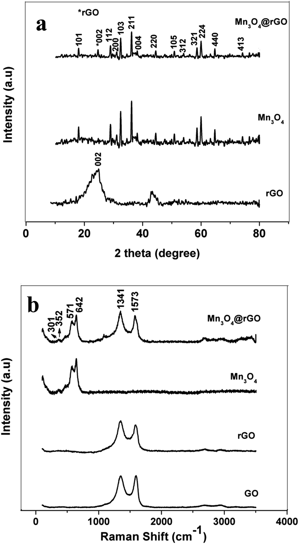 | ||
| Fig. 1 (a) XRD pattern of rGO, Mn3O4 and Mn3O4@rGO. (b) Laser Raman spectra of GO, rGO, Mn3O4 and Mn3O4@rGO. | ||
The chemical composition and chemical bonding states of the Mn3O4@rGO composite are further examined using XPS. The survey spectrum (Fig. 2a) confirms the presence of Mn, O and C elements with no other impurities. The high resolution C 1s XPS (Fig. 2b) spectrum shows three components centered at viz., 284.2, 285.4, and 288.2 eV; the strong C 1s peak (284.2 eV) represents sp2 carbon in the reduced graphene network, whereas the weaker ones originated from the oxygenated functional groups of carbon (285.4 eV – carbon in C–O, 288.2 eV – carbonyl carbon C![[double bond, length as m-dash]](https://www.rsc.org/images/entities/char_e001.gif) O).39,40 The obtained result reveals that the functional groups in GO are substantially removed after NaBH4 reduction. The Mn 2p XPS peak (Fig. 2c) can be resolved into two components i.e. 641.8 and 653.2 eV which are attributed to Mn 2p3/2 and Mn 2p1/2 levels respectively and the energy gap between the two levels is 11.4 eV confirming the formation of Mn3O4. The obtained binding energies of Mn 2p agree well with earlier reports41,42 for Mn3O4. Fig. 2d displays the deconvoluted XPS spectrum of O 1s resolved into two components viz., at 529.7 and 530.8 ev which are attributed to the Mn–O–Mn bond for oxides and Mn–O–H for hydroxides respectively.41 The above obtained results of Mn3O4 and rGO are quite consistent with the results of XRD and Raman. The surface area of the synthesized Mn3O4 and Mn3O4@rGO composite is investigated using nitrogen adsorption–desorption isotherms measured at 77 K (Fig. 2e). According to IUPAC nomenclature, both materials exhibit a type II isotherm indicating multilayer adsorption without a hysteresis loop between adsorption and desorption which is a characteristic form of non-porous materials. The calculated BET surface areas of the Mn3O4 and Mn3O4@rGO composite are 103.3 and 110.4 m2 g−1 respectively. The large surface area of the composite implies that the nanocomposite architecture facilitates easy access of electrolyte ions to the electrode surface and diffusion during charge/discharge, which are beneficial for improving the electrochemical performance.
O).39,40 The obtained result reveals that the functional groups in GO are substantially removed after NaBH4 reduction. The Mn 2p XPS peak (Fig. 2c) can be resolved into two components i.e. 641.8 and 653.2 eV which are attributed to Mn 2p3/2 and Mn 2p1/2 levels respectively and the energy gap between the two levels is 11.4 eV confirming the formation of Mn3O4. The obtained binding energies of Mn 2p agree well with earlier reports41,42 for Mn3O4. Fig. 2d displays the deconvoluted XPS spectrum of O 1s resolved into two components viz., at 529.7 and 530.8 ev which are attributed to the Mn–O–Mn bond for oxides and Mn–O–H for hydroxides respectively.41 The above obtained results of Mn3O4 and rGO are quite consistent with the results of XRD and Raman. The surface area of the synthesized Mn3O4 and Mn3O4@rGO composite is investigated using nitrogen adsorption–desorption isotherms measured at 77 K (Fig. 2e). According to IUPAC nomenclature, both materials exhibit a type II isotherm indicating multilayer adsorption without a hysteresis loop between adsorption and desorption which is a characteristic form of non-porous materials. The calculated BET surface areas of the Mn3O4 and Mn3O4@rGO composite are 103.3 and 110.4 m2 g−1 respectively. The large surface area of the composite implies that the nanocomposite architecture facilitates easy access of electrolyte ions to the electrode surface and diffusion during charge/discharge, which are beneficial for improving the electrochemical performance.
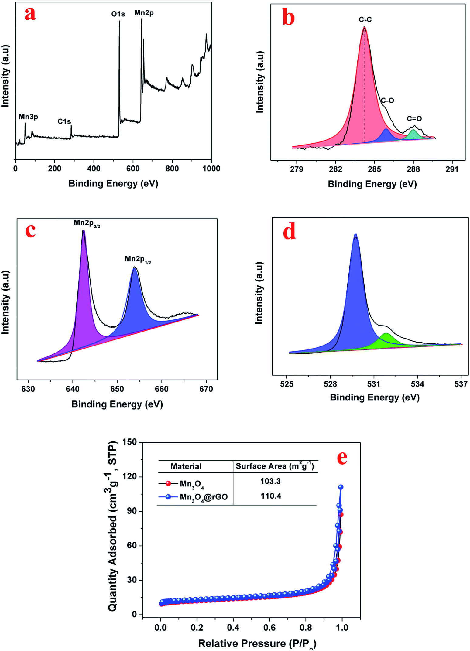 | ||
| Fig. 2 XPS of the Mn3O4@rGO composite, (a) survey spectrum (b) C 1s (c) Mn 2p (d) O 1s and (e) nitrogen adsorption–desorption isotherms (T – 77 K) of Mn3O4 and the Mn3O4@rGO composite. | ||
The morphology and microstructure of the synthesized materials are investigated using SEM and HRTEM analysis. SEM images of GO, rGO, Mn3O4 and Mn3O4@rGO composites are shown in Fig. S2.† Both GO and rGO showed micron sized flake like morphology. A spherical morphology is observed in both cases of Mn3O4 (Fig. S2c†) and Mn3O4@rGO (Fig. S2d†) composites with a particle size in the range of 80–110 nm. At higher magnification, rGO sheets are not clearly visible in the composite; however, at low magnification (inset in Fig. S2d†) rGO sheets are observed with Mn3O4 particles on its surface. This is further examined by using HRTEM analysis. Fig. 3 depicts the HRTEM images with different magnifications and SAED patterns of Mn3O4@rGO composites. Spherical Mn3O4 particles with a size of 30–60 nm are clearly observed on the surface of rGO sheets (Fig. 3a). Fig. 3b shows the HRTEM image of the Mn3O4@rGO composite at higher magnification. The SAED pattern (Fig. 3c) also confirmed the presence of both rGO and Mn3O4 phases in the composites.
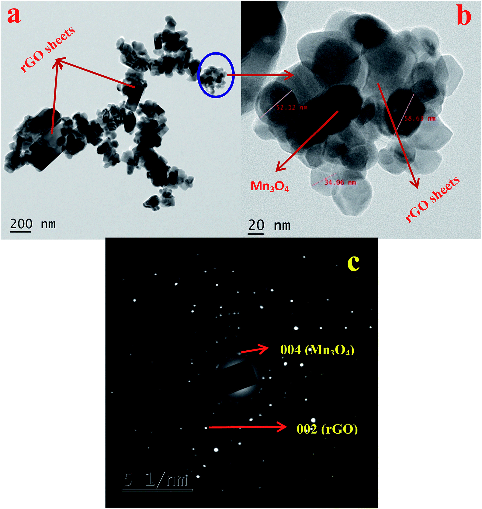 | ||
| Fig. 3 HRTEM images of (a) Mn3O4@rGO and (b) Mn3O4@rGO at high magnification. (c) SAED pattern of Mn3O4@rGO. | ||
The electrochemical properties of Mn3O4 and Mn3O4@rGO as anodes for KIBs are examined in half cells where K ingot is used as the reference electrode in 2032 type coin cells in a potential window between 0.01 and 3 V at a scan rate of 0.1 mV s−1. Fig. 4a and b presents the cyclic voltammograms of Mn3O4 and Mn3O4@rGO composites for the initial three cycles respectively. During the first cathodic scan, a reduction peak is obtained at around 1.22 V which is attributed to the initial reduction of Mn3O4 (Mn3O4 + 2 K+ + 2e− → 3MnO + K2O). The broad cathodic peak from 0.86–0.26 V is attributed to the formation of a SEI film and the reduction of MnO to Mn (MnO + 2 K+ + 2e− → Mn + K2O). To confirm the formation of MnO and Mn during reduction we discharged the cells at different potential states i.e., 1.05 V and 0.204 V and then we carried out ex situ XRD (Fig. 4c). The ex situ XRD patterns clearly confirm the formation of MnO and K2O in the potential region of 1.12 V and the formation of Mn and K2O at a potential of 0.204 V. In the anodic sweep, the two broad peaks obtained at around 0.52 and 1.53 V are assigned to the oxidation of metallic Mn and decomposition26,27 of K2O. This is further confirmed from ex situ XRD patterns when the cell is charged up to 1.6 V. Except the first CV curve, the 2nd and 3rd CV profiles almost overlap indicating the good reversibility of Mn3O4 and Mn3O4@rGO composites. Fig. 4d compares the CV profiles of rGO, Mn3O4 and Mn3O4@rGO composites in the potential window between 0.01 and 3 V, except that rGO is scanned between 0.01 and 1.5 V because the typical intercalation/deintercalation of rGO mostly occurs between these potential limits.43,44 Except peak current intensities, the CV profiles of both pristine and composite materials are almost similar which clearly confirms that rGO does not take part in the redox reaction of Mn3O4; however, it acts as a matrix during potassium intercalation/deintercalation. Based on the signature peaks, the storage behaviour of potassium in Mn3O4 and Mn3O4@rGO follows the same kinetics as LIBs26,27 and NIBs.24
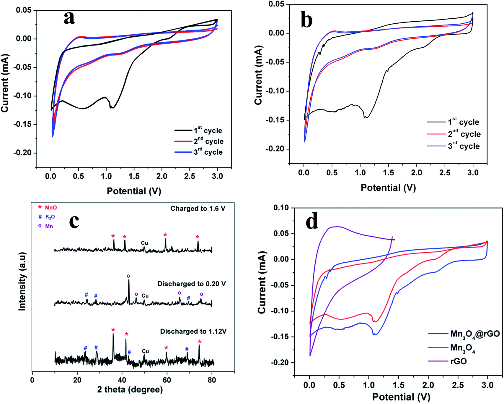 | ||
| Fig. 4 CV curves at a scan rate of 0.1 mVs−1 for (a) Mn3O4 and (b) Mn3O4@rGO. (c) Ex situ XRD patterns of Mn3O4@rGO at different discharged and charged states (d) CV curves of rGO, Mn3O4 and Mn3O4@rGO at a scan rate of 0.1 mV s−1. | ||
In order to further confirm the potassium storage phenomenon in pristine Mn3O4 and Mn3O4@rGO (85:15) composites, we carried out galvanostatic charge/discharge studies (Fig. 5a) between the potential limits of 0.01 and 3 V (0.01–1.5 V for rGO43,44) at a current density of 100 mA g−1 (0.1 A g−1). During the first discharge, a plateau is obtained between the potential region of 1.42 and 1.12 V corresponding to the reduction of Mn3O4 (Mn3O4 + 2K+ + 2e− → 3MnO + K2O). A sloping voltage profile is seen from 0.85 to 0.2 V which is attributed to SEI formation and the reduction of MnO to Mn (MnO + 2K+ + 2e− → Mn + K2O). These potential regions yield discharge capacities of 1263 and 1215 mA h g−1 for Mn3O4 and Mn3O4@rGO composites respectively. The discharge capacities of both pristine and composites materials are more than the theoretical capacity of Mn3O4 which is attributed to the conversion reaction and SEI formation. The first charge curve shows a voltage plateau at around 0.53 V, consistent with the oxidation of Mn to MnO and decomposition of the K2O phase. Charge capacities of 643 and 802 mA h g−1 are obtained at the end of the first charging process. It is interesting to note that the charge and discharge profiles of both pristine and composites materials are quite consistent with the CV profiles and also indicates that rGO does not take part in the electrochemical reaction of Mn3O4 in the composites; however, it acts as a conductive matrix to enhance the charge capacity of Mn3O4. To further evaluate the electrochemical behavior of the Mn3O4@rGO composite, we performed charge/discharge studies for different compositions of Mn3O4 and rGO (80:20, 90:10 and 95:05) at a current density of 0.1 A g−1. The charge capacities (inset in Fig. 5b) are 748, 802, 716 and 677 for 80:20, 85:15, 90:10 and 95:05 (Mn3O4:rGO) respectively and the corresponding capacity retentions (Fig. 5b) are 85.6, 97.7, 91.6 and 88.7% respectively after 100 cycles. From this we optimized the composition of rGO in the composite to 15% which performs better in terms of capacity and capacity retention than the other compositions.
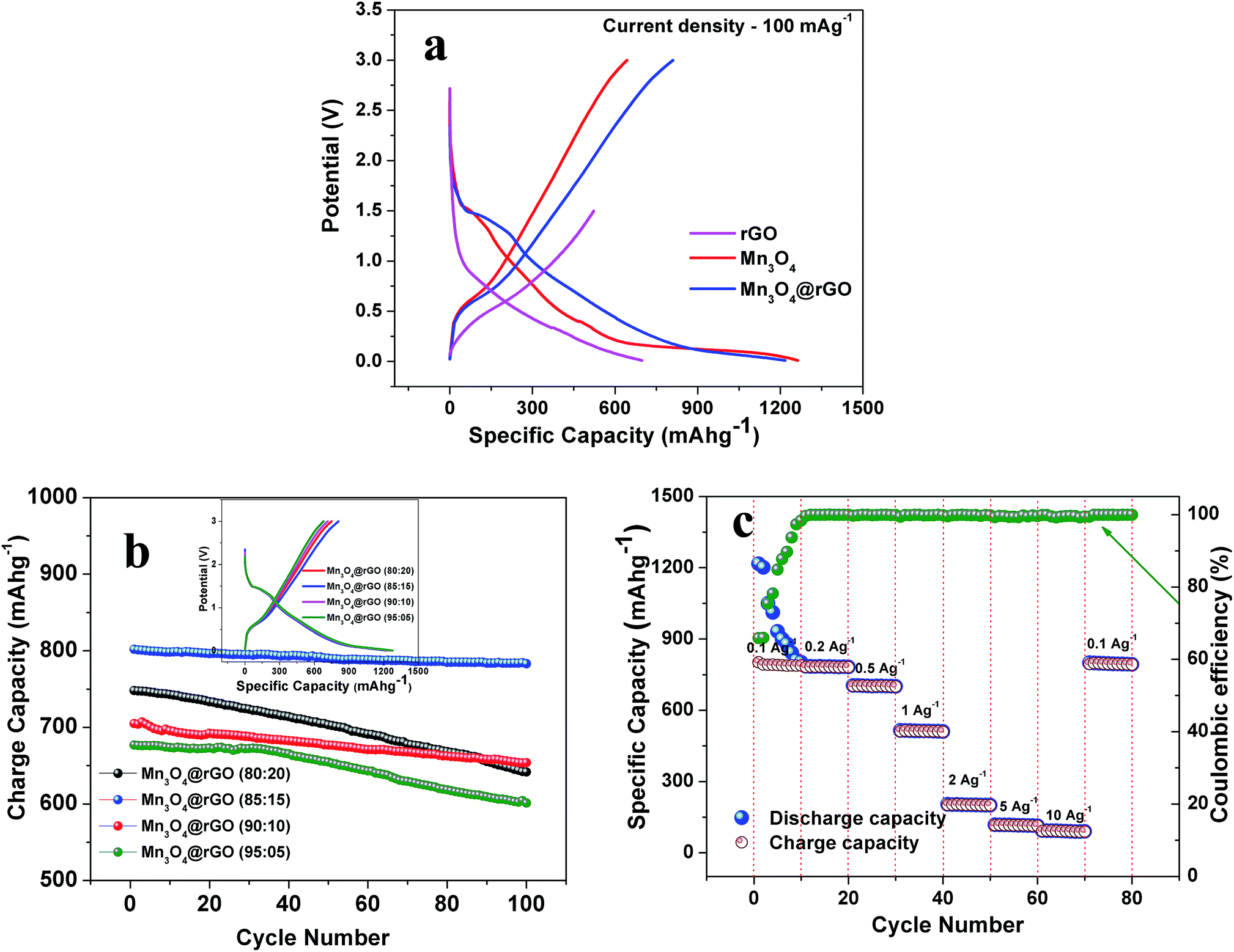 | ||
| Fig. 5 (a) First charge/discharge curves at a current density of 100 mA g−1, (b) cycling performance of Mn3O4@rGO over 100 cycles (inset shows the first charge/discharge curves of different compositions of Mn3O4@rGO at a current density of 100 mA g−1) and (c) rate capability of Mn3O4@rGO at different current densities. | ||
In addition to the high capacity and better cycling stability of Mn3O4@rGO (85:15), an outstanding rate capability is also achieved at different current densities from 0.1–10 A g−1 (Fig. 5c). The nanocomposite exhibits reversible capacities of 802, 781, 704, 512, 201, 116 and 95 mA h g−1 at the corresponding current densities of 0.1, 0.2, 0.5, 1, 2, 5 and 10 A g−1 respectively. It is very interesting to note that as the current density returns back to 0.1 A g−1, the cell still delivers 795 mA h g−1 indicating good rate performances and structural stability. The coulombic efficiency is initially dropped to 66% and after 10 cycles over 99.5% is maintained and finally it reaches more than 99.99% at the end of the 80th cycle.
The long term cycling stability of Mn3O4 and Mn3O4@rGO is evaluated at a current density of 0.5 Ag−1 over 500 cycles as shown in Fig. 5a. The pristine and composite delivered initial charge capacities of 552 and 704 mA h g−1 whereas the 500th cycle capacities are 90.7 and 635 mA h g−1 respectively and the corresponding capacity retentions are 16.4 and 90.2%. The coulombic efficiencies of both pristine and composite materials dropped initially and then were maintained over more than 99% in subsequent cycles. The composite shows relatively good cycling stability which is considerably higher than that of pristine Mn3O4. The poor capacity retention of Mn3O4 is mainly due to the structural instability during cycling which is confirmed from the ex situ XRD pattern (Fig. 5b) of the cycled electrode after 500 cycles. The pristine Mn3O4 electrode undergoes large volume expansion during the process of potassium intercalation/deintercalation resulting in the breakdown of the electrode architecture and loss of electrical contact between the current collector and the electrode material.45 More interestingly, the composite delivers a stable reversible capacity even after 500 cycles which suggests that rGO accommodates large volume expansion of Mn3O4 during cycling which is confirmed from the ex situ XRD pattern of the composite. The outstanding electrochemical performance of the Mn3O4@rGO composite is mainly attributed to its special architecture. The nanoscale spherical particles offer a very high surface area allowing potassium ions to easily go in and out of the Mn3O4 structure and subsequently the volume expansion is accommodated by the rGO network which maintains the structural integrity of the electrode. This is further evidenced by ex situ HRTEM analysis as shown in Fig. 6c and d. It is interesting to note that the spherical morphology of the Mn3O4 is preserved on the surface of rGO sheets even after 500 cycles. Both Mn3O4 crystal structure and rGO phase are also retained and confirmed by SAED patterns (Fig. 6d) of the composite. The HRTEM image of the composite appears a little hazy which may be due to conductive carbon and PVDF used for electrode coating. Even the obtained capacity, cycling stability and rate capability are better and comparable to those of sponge23 like-Mn3O4 (∼798 mA h g−1 after 40 cycles at 37 mA g−1 for LIBs), Mn3O4 (∼200 mA h g−1 after 10 cycles at 40 mA g−1),26 Mn3O4-graphene microflowers22 (∼425 mA h g−1 after 500 cycles at 0.5 A g−1 for LIBs, ∼198 mA h g−1 after 200 cycles at 0.2 A g−1 for NIBs, and ∼150 mA h g−1 after 100 cycles for KIBs), Mn3O4 nanotubes encapsulated by porous graphene24 (800 mA h g−1 after 200 cycles at 0.1 A g−1 for LIBs and ∼200 mA h g−1 after 50 cycles at 0.05 A g−1 for NIBs), Mn3O4@C core–shell composites46 (∼765 mA h g−1 after 100 cycles at 0.5 A g−1 for LIBs), Mn3O4@GNS47 (∼1100 mA h g−1 after 100 cycles at 0.1 A g−1 for LIBs), Mn3O4 nanorods47 (∼375 mA h g−1 after 100 cycles at 0.1 Ag−1 for LIBs), Mn3O4@rGO27 (∼702 mA h g−1 after 100 cycles at 0.1 A g−1 for LIBs), and Mn3O4 nanorods27 (∼171 mA h g−1 after 100 cycles at 0.1 A g−1 for LIBs). Form this we clearly understood that the as-synthesized Mn3O4nanospheres@rGO architecture performs much better than previously reported Mn3O4/graphene/carbon composites for NIBs22,24 and KIBs22 (see the ESI Table S1†).
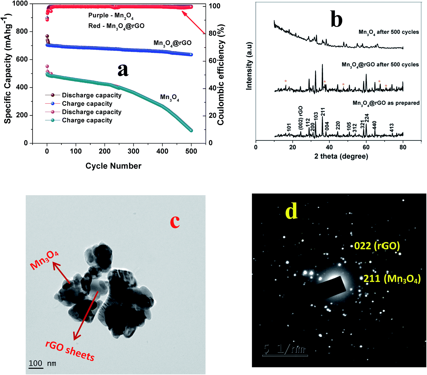 | ||
| Fig. 6 (a) Cycling performance of Mn3O4 and Mn3O4@rGO over 500 cycles at a current density of 0.5 A g−1, (b) XRD patterns before and after 500 cycles and (c) HRTEM image and (d) SAED pattern of Mn3O4@rGO after 500 cycles. | ||
In order to explain the excellent high-rate performance of the Mn3O4 nanospheres@rGO composite, we examined the redox pseudocapacitance-like contribution in the composite by analyzing the kinetics of pristine Mn3O4 and Mn3O4@rGO composite electrodes to separate the capacitive controlled and diffusion controlled capacity contribution.48,49 In this we mainly consider the following three charge storage mechanisms:50,51 (i) faradaic contributions from the diffusion controlled conversion reaction, (ii) faradaic contribution associated with the extrinsic pseudocapacitance effect i.e. charge transfer with surface/subsurface atoms and (iii) non-faradaic contribution associated with the electrical double layer effect. Step-wise kinetic studies are carried out by CV experiments for both electrodes at various scan rates from 0.2 to 1.2 mV s−1. Resulting from the step-wise potassiation mechanism, CV curves of similar contours are obtained for both electrodes (Fig. S2a† and 7a) at various scan rates from 0.2 to 1.2 mV s−1. The faradaic and non-faradaic mechanisms can be quantitatively analyzed from CV measurements using the following formula
| i = aνb | (1) |
| i(V) = k1ν + k2ν1/2 | (2) |
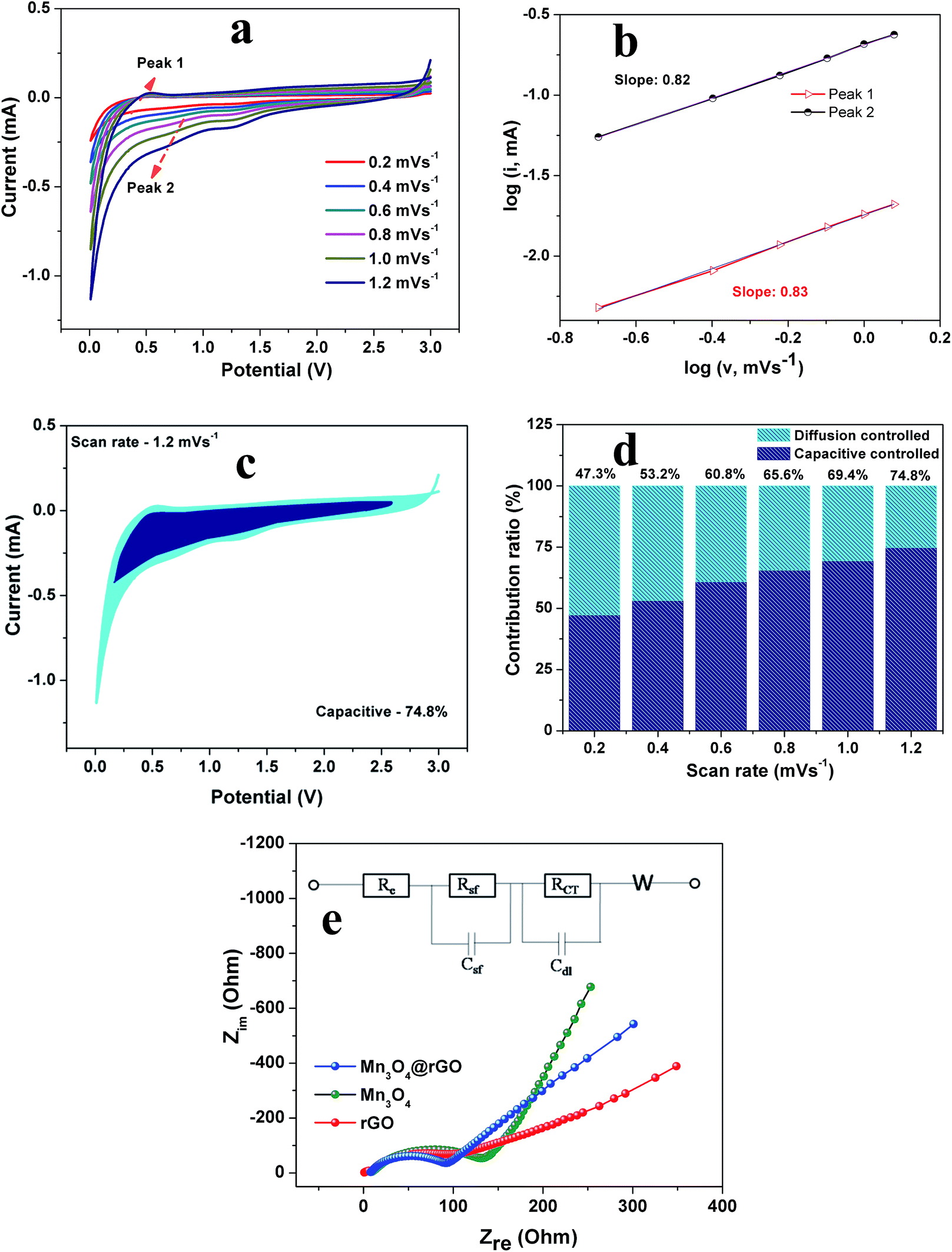 | ||
| Fig. 7 (a) CV curves of Mn3O4@rGO at various scan rates, (b) logi vs. logv plots at oxidation and reduction states, (c) capacitive contribution of Mn3O4@rGO at 1.2 mV s−1, (d) normalized contribution ratio of capacitive and diffusion controlled capacities of Mn3O4@rGO at various scan rates and (e) Nyquist plots of rGO, Mn3O4 and Mn3O4@rGO (inset: equivalent circuit). | ||
To obtain further insights into the effect of nanospheres on the improved electrochemical performance, we performed EIS measurements. Fig. 7e depicts the Nyquist plots of rGO, Mn3O4 and Mn3O4@rGO electrodes and the inset shows the fitted equivalent circuit model (fitted plots are shown in Fig. S3† and the parameters are listed in Table S2†). All EIS spectra are composed of semicircles in the high-medium frequency region (attributed to the charge transfer resistance) and straight lines in the low frequency region (ascribed to the mass transfer of K+ ions). The circuit elements Rs, Rsf and Rct denote the electrolyte resistance, SEI film resistance and charge transfer resistance of the electrode–electrolyte interface respectively. Csf, Cdl and W are capacitance associated with the SEI film, double layer capacitance and Warburg resistance respectively. A depressed semicircle is observed for the Mn3O4 nanospheres@rGO composite as compared to pristine Mn3O4 which suggests that the conductivity of Mn3O4 nanospheres is greatly enhanced by the rGO network. The charge transfer resistance Rct of Mn3O4@rGO (92.7 Ω) is much lower than that of pristine Mn3O4 (155.3 Ω) suggesting that the composite possesses excellent conductivity and fast K+ ion kinetics.
The potassium ion diffusion coefficients are also evaluated using the following equation
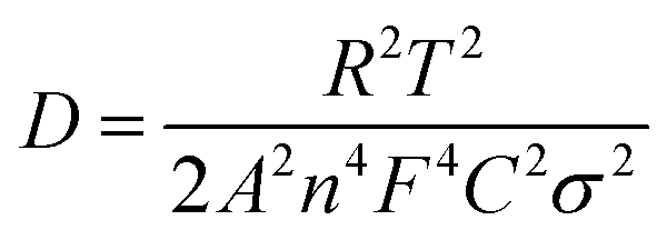 | (3) |
The superior electrochemical performance in terms of high capacity, excellent cycling stability and good rate capability of the as-synthesized Mn3O4 nanospheres@rGO architecture is mainly attributed to the intimate interaction between Mn3O4 nanospheres and the conductive graphene network which creates more electrochemically active sites in Mn3O4 nanospheres. Thus the high surface area nanosphere@graphene architecture could effectively facilitate the movement of charge carriers back and forth from Mn3O4 nanospheres through the highly conducting graphene network to the current collector. Moreover, this special architecture provides a large electrode–electrolyte interface and short ion diffusion path length and the graphene network enhances the conductivity of Mn3O4 nanospheres which are beneficial for high electrochemical activity. Hence, the high surface area graphene network highly accommodates the huge volume expansion during repeated cycling resulting in good structural and cycling stability.
Conclusions
In summary, a Mn3O4 nanospheres@rGO special architecture is successfully obtained by the precipitation method followed by ultrasonication. The special architecture composite anode exhibits a high capacity of 802 mA h g−1 at 0.1 A g−1, outstanding cycling stability of 90% even after 500 cycles (635 mA h g−1) at 0.5 A g−1 and superior rate capability (95 mA h g−1 even at 10 A g−1). Moreover, the significant capacitive contribution, i.e., surface-dominated extrinsic pseudocapacitance, is recognized as a major energy storage mechanism in favour of high capacity, excellent cycling stability and fast K+ uptake. The ex situ XRD patterns clearly confirmed the reduction of Mn3O4 during discharge and oxidation of Mn to MnO during charge. Furthermore, the morphology and structure of the Mn3O4 nanospheres@rGO special architecture were also retained even after 500 cycles which is also confirmed by ex situ XRD and HRTEM analysis. The unique electrode architecture design accommodated volume expansion during cycling and also provides good electrolyte accessibility and short diffusion pathways for electrochemical reactions. The obtained results and unique architecture may pave a new way to improve the electrochemical performance of electrode materials towards KIBs.Conflicts of interest
There are no conflicts to declare.Acknowledgements
One of the authors, Dr C. Nithya, wishes to thank the Department of Science and Technology, India, for DST-Women Scientist Award (SR/WOS-A/CS-20/2017).Notes and references
- Y. Jianchao, C. Andreas, Y. Baumgaertel, W. Morris, B. Juergen and M. B. Monika, Structural Optimization of 3D Porous Electrodes for High-Rate Performance Lithium Ion Batteries, ACS Nano, 2015, 9, 2194–2202 CrossRef PubMed.
- X. Dongbin, L. Xifei, B. Zhimin, S. Hui, F. Linlin, W. Chunxia, L. Dejun and L. Shigang, Superior Cathode Performance of Nitrogen-Doped Graphene Frameworks for Lithium Ion Batteries, ACS Appl. Mater. Interfaces, 2017, 9, 10643–10651 CrossRef PubMed.
- R. J. Antonia, K. Richard, W. Ralf, C. R. Uta, K. Martin, N. Roman, W. Martin and P. Tobias, A Step Toward High-Energy Silicon-Based Thin Film Lithium Ion Batteries, ACS Nano, 2017, 11, 4731–4744 CrossRef PubMed.
- Y. Yuki, F. Keizo, S. Keitaro, K. Keisuke, Y. Makoto, T. Yoshitaka and Y. Atsuo, Unusual Stability of Acetonitrile-Based Superconcentrated Electrolytes for Fast-Charging Lithium-Ion Batteries, J. Am. Chem. Soc., 2014, 136, 5039–5046 CrossRef PubMed.
- E. Vinodkumar, N. H. Chulgi, T. Jialiang and G. P. Vilas, Cobalt Nanoparticles Chemically Bonded to Porous Carbon Nanosheets: A Stable High-Capacity Anode for Fast-Charging Lithium-Ion Batteries, ACS Appl. Mater. Interfaces, 2018, 10, 4652–4661 CrossRef PubMed.
- J. M. Tarascon, Is Lithium the New Gold?, Nat. Chem., 2010, 2, 510 CrossRef CAS PubMed.
- P. Jun, C. Shulin, F. Qiang, S. Yuanwei, Z. Yuchen, L. Na, G. Peng, Y. Jian and Q. Yitai, Layered-Structure SbPO4/Reduced Graphene Oxide: An Advanced Anode Material for Sodium Ion Batteries, ACS Nano, 2018, 12, 12869–12878 CrossRef PubMed.
- L. Rui, L. Haodong, S. Tian, Z. Shiyao, Z. Guiming, Z. Guorui, L. Ziteng, F. O. Gregorio, Z. Weimin, M. Jinxiao and Y. Yong, Novel 3.9 V Layered Na3V3(PO4)4 Cathode Material for Sodium Ion Batteries, ACS Appl. Energy Mater., 2018, 1, 3603–3606 CrossRef.
- L. Yu, Q. Lei, L. Ruliang, C. L. Kah, W. Yiying, Z. Dengyun, L. Baohua and K. Feiyu, Exploring Stability of Nonaqueous Electrolytes for Potassium-Ion Batteries, ACS Appl. Energy Mater., 2018, 1, 1828–1833 Search PubMed.
- H. Xingkang, L. Dan, G. Xiaoru, S. Xiaoyu, Q. Deyang and C. Junhong, Phosphorus/Carbon Composite Anode for Potassium-Ion Batteries: Insights into High Initial Coulombic Efficiency and Superior Cyclic Performance, ACS Sustainable Chem. Eng., 2018, 6, 16308–16314 CrossRef.
- Abundance in Earth's Crust: Periodicity, 2017,https://www.webelements.com/periodicity/abundance_crust/.
- W. Qiannan, Z. Xinxin, N. Chaolun, T. He, L. Jixue, Z. Ze, X. M. Scott, W. Jiangwei and X. Yunhua, Reaction and Capacity-Fading Mechanisms of Tin Nanoparticles in Potassium-Ion Batteries, J. Phys. Chem. C, 2017, 121, 12652–12657 CrossRef.
- Z. Jing, Y. Yong, F. Xiulin, J. Guangbin, J. Xiao, W. Haiyang, H. Singyuk, R. Z. Michael and W. Chunsheng, Extremely stable antimony–carbon composite anodes for potassium-ion batteries, Energy Environ. Sci., 2019, 12, 615–623 RSC.
- X. Qing, L. Dongning, H. Yongxin, Z. Xiaoxiao, Y. Yusheng, F. Ersha, L. Li, W. Feng and C. Renjie, Vitamin K as a high-performance organic anode material for rechargeable potassium ion batteries, J. Mater. Chem. A, 2018, 6, 12559–12564 RSC.
- S. Irin, R. Md Mokhlesur, R. Thrinathreddy, C. Ying and M. G. Alexey, High capacity potassium-ion battery anodes based on black phosphorus, J. Mater. Chem. A, 2017, 5, 23506–23512 RSC.
- N. Xiaogang, Z. Yuchuan, T. Lulu, Y. Zhao, Y. Jie, L. Tong, Z. Liang, Z. Yujie and G. Lin, Amorphous FeVO4 as a promising anode material for potassium-ion batteries, Energy Storage Materials, 2019 DOI:10.1016/j.ensm.2019.01.011.
- S. Irin, R. Md Mokhlesur, C. Ying and M. G. Alexey, Potassium-Ion Battery Anode Materials Operating through the Alloying–Dealloying Reaction Mechanism, Adv. Funct. Mater., 2017, 28, 1703857–1703875 Search PubMed.
- J. Mitch, Tin-phosphorus anodes for potassium-ion batteries, Chem. Eng. News, 2017, 95, 11 Search PubMed.
- K. Brij, G. Venkatesh and N. Munichandraiah, K2Ti4O9: A Promising Anode Material for Potassium Ion Batteries, J. Electrochem. Soc., 2016, 163, A2551–A2554 CrossRef.
- M. Imran, W. Shuo, L. Junyi, X. Huanhuan and S. Qiang, Boron-graphdiyne as an anode material for Li, Na, and K ion batteries with high capacities and low diffusion barriers, J. Renew. Sustain. Energy, 2019, 11, 014106 CrossRef.
- C. Wei-Chung, W. Jen-Hsuan, C. Kuan-Ting and T. Hsing-Yu, Red Phosphorus Potassium-Ion Battery Anodes, Adv. Sci., 2019, 6, 1801354–1801363 CrossRef PubMed.
- T. Chen, X. Fangyu, Y. Xuhui, T. Shuangshuang, L. Binxu, A. Qinyou, L. Ping and M. Liqiang, Hierarchical Mn3O4/Graphene Microflowers Fabricated via a Selective Dissolution Strategy for Alkali-Metal-Ion Storage, ACS Appl. Mater. Interfaces, 2019, 11, 14120–14125 CrossRef PubMed.
- G. Jie, A. L. Michael and D. A. Hector, Sponge like Nanosized Mn3O4 as a High-Capacity Anode Material for Rechargeable Lithium Batteries, Chem. Mater., 2011, 23, 3223–3227 CrossRef.
- W. Beibei, L. Fei, W. Xiujuan, W. Gang, W. Hui and B. Jintao, Mn3O4 nanotubes encapsulated by porous graphene sheets with enhanced electrochemical properties for lithium/sodium-ion batteries, Chem. Eng. J., 2019, 364, 57–69 CrossRef.
- K. Liu, F. Zou, Y. Sun, Z. Yu, X. Liu, L. Zhou, Y. Xia, B. D. Vogt and Y. Zhu, Self assembled Mn3O4/C nanospheres as high performance anode materials for lithium-ion batteries, J. Power Sources, 2018, 395, 92–97 CrossRef CAS.
- W. Hailiang, C. Li-Feng, Y. Yuan, S. C. Hernan, T. R. Joshua, L. Yongye, C. Yi and D. Hongjie, Mn3O4-Graphene Hybrid as a High-Capacity Anode Material for Lithium Ion Batteries, J. Am. Chem. Soc., 2010, 132, 13978–13980 CrossRef PubMed.
- W. Jian-Gan, J. Dandan, Z. Rui, L. Xu, L. Xing-rui, S. Chao, X. Keyu, L. Baohua, K. Feiyu and W. Bingqing, Highly Flexible Graphene/Mn3O4 Nanocomposite Membrane as Advanced Anodes for Li-Ion Batteries, ACS Nano, 2016, 10, 6227–6234 CrossRef PubMed.
- L. Shuang, L. Y. Li, S. Yu-Ting, F. Jun, L. Rong-Bing, F. Gai-Di, X. Wei-Ling and Z. Jing-Tai, Greatly Enhanced Faradic Capacities of 3D Porous Mn3O4/G Composites as Lithium-Ion Anodes and Supercapacitors by C−O−Mn Bonding, ACS Appl. Mater. Interfaces, 2019, 11, 10178–11018 CrossRef PubMed.
- H. Wang, L. Cui, Y. Yang, H. S. Casalongue, J. T. Robinson, Y. Liang, Y. Cui and H. Dai, Mn3O4–Graphene Hybrid as a High-Capacity Anode Material for Lithium Ion Batteries, J. Am. Chem. Soc., 2010, 132, 13978–13980 CrossRef CAS PubMed.
- P. Rosaiah, Z. Jinghui, S. Dadamiah PMD, O. M. Hussain, Q. Yejun and Z. Lei, Reduced graphene oxide/Mn3O4 nanocomposite electrodes with enhanced electrochemical performance for energy storage applications, J. Electroanal. Chem., 2017, 794, 78–85 CrossRef CAS.
- W. S. Hummers and R. E. Offeman, Preparation of Graphitic oxide, J. Am. Chem. Soc., 1958, 80, 1339 CrossRef CAS.
- P. Vishnuprakash, C. Nithya and M. Premalatha, Exploration of V2O5 nanorod@rGO heterostructure as potential cathode material for potassium-ion batteries, Electrochim. Acta, 2019, 309, 234–241 CrossRef CAS.
- B. Nikoobakht and M. A. El-Sayed, Evidence for Bilayer Assembly of Cationic Surfactants on the Surface of Gold Nanorods, Langmuir, 2001, 17, 6368–6374 CrossRef CAS.
- L. Stobinski, B. Lesiak, A. Malolepszy, M. Mazurkiewicz, B. Mierzwa, J. Zemek, P. Jiricek and I. Bieloshapka, Graphene oxide and reduced graphene oxide studied by the XRD, TEM and electron spectroscopy methods, J. Electron. Spectrosc. Relat. Phenom., 2014, 195, 145–154 CrossRef CAS.
- C. Wang, L. Yin, D. Xiang and Y. Qi, Uniform Carbon Layer Coated Mn3O4 Nanorod Anodes with Improved Reversible Capacity and Cyclic Stability for Lithium Ion Batteries, ACS Appl. Mater. Interfaces, 2012, 4, 1636–1642 CrossRef CAS PubMed.
- Z. Yang, L. Guo, W. Shi, X. Zou, B. Xiang and S. Xing, Rapid Production of Mn3O4/rGO as an Efficient Electrode Material for Supercapacitor by Flame Plasma, Materials, 2018, 11, 881–894 CrossRef PubMed.
- H. U. Shah, F. Wang, M. S. Javed, N. Shaheen, M. Saleem and Y. Li, Hydrothermal synthesis of reduced graphene oxide – Mn3O4 nanocomposite as an efficient electrode materials for supercapacitors, Ceram. Int., 2018, 44, 3580–3584 CrossRef.
- J. G. Wang, C. Zhang and F. Kang, Nitrogen-Enriched Porous Carbon Coating for Manganese Oxide Nanostructures towards High− Performance Lithium−Ion Batteries, ACS Appl. Mater. Interfaces, 2015, 7, 9185–9194 CrossRef CAS PubMed.
- C. Cai, L. Xu, M. Yan, C. Han, L. He, K. M. Hercule, C. Niu, Z. Yuan, W. Xu and L. Qu, Manganese Oxide/Carbon Yolk− Shell Nanorod Anodes for High Capacity Lithium Batteries, Nano Lett., 2015, 15, 738–744 CrossRef PubMed.
- S. Stankovich, R. D. Piner, X. Q. Chen, N. Q. Wu, S. T. Nguyen and R. S. Ruoff, Stable aqueous dispersions of graphitic nanoplatelets via the reduction of exfoliated graphite oxide in the presence of poly(sodium 4-styrenesulfonate), J. Mater. Chem., 2006, 16, 155–158 RSC.
- C. Wang, L. Yin, D. Xiang and Y. Qi, Uniform Carbon Layer Coated Mn3O4 Nanorod Anodes with Improved Reversible Capacity and Cyclic Stability for Lithium Ion Batteries, ACS Appl. Mater. Interfaces, 2012, 4, 1636–1642 CrossRef CAS PubMed.
- P. Hai-Jun, H. Gui-Xia, C. Zhao-Hua, L. Jia, L. Xiao-Ming and C. Yue-Peng, Mesoporous Mn3O4/C Microspheres Fabricated from MOF Template as Advanced Lithium-Ion Battery Anode, Cryst. Growth Des., 2017, 17, 5881–5886 CrossRef.
- D. Yoon, K. Y. Chung, W. Chang, S. M. Kim, M. J. Lee, Z. Lee and J. Kim, Hydrogen-Enriched Reduced Graphene Oxide with Enhanced Electrochemical Performance in Lithium Ion Batteries, Chem. Mater., 2015, 27, 266–275 CrossRef CAS.
- R. Mukherjee, A. V. Thomas, A. Krishnamurthy and N. Koratkar, Photothermally Reduced Graphene as High-Power Anodes for Lithium-Ion Batteries, ACS Nano, 2012, 6, 7867–7878 CrossRef CAS PubMed.
- G. W. Li, B. M. Zhang, F. Yu, A. A. Novakova, M. S. Krivenkov, T. Y. Kiseleva, L. Chang, J. C. Rao, A. O. Polyakov, G. R. Blake, R. A. D. Groot and T. T. M. Palstra, High-purity Fe3S4 Greigite Microcrystals for Magnetic and Electrochemical Performance, Chem. Mater., 2014, 26, 5821–5829 CrossRef CAS.
- X. Ma, Y. Zhai, N. Wang, J. Yanga and Y. Qian, Mn3O4@C core–shell composites as an improved anode for advanced lithium ion batteries, RSC Adv., 2015, 5, 46829–46833 RSC.
- W. Lu-Lu, Z. Dong-Lin, C. Xing-Wang, D. Ze-Wen, H. Tao and M. Shuo, Nanorod Mn3O4 anchored on graphene nanosheet as anode of lithium ion batteries with enhanced reversible capacity and cyclic performance, J. Alloys Compd., 2017, 728, 383–390 CrossRef.
- T. Brezesinski, J. Wang, S. H. Tolbert and B. Dunn, Ordered mesoporous alpha MoO3 with iso-oriented nanocrystalline walls for thin-film pseudocapacitors, Nat. Mater., 2010, 9, 146–151 CrossRef CAS PubMed.
- G. A. Muller, J. B. Cook, H. S. Kim, S. H. Tolbert and B. Dunn, High performance pseudocapacitor based on 2D layered metal chalcogenide nanocrystals, Nano Lett., 2015, 15, 1911–1917 CrossRef CAS.
- D. Chao, C. Zhu, P. Yang, X. Xia, J. Liu, J. Wang, X. Fan, S. V. Savilov, J. Lin, H. . . J. Fan and Z. X. Shen, Array of nanosheets render ultrafast and high-capacity Na-ion storage by tunable pseudocapacitance, Nat. Commun., 2016, 7, 12122–12130 CrossRef CAS PubMed.
- C. Chen, Y. Wen, X. Hu, X. Ji, M. Yan, L. Mai, P. Hu, B. Shan and Y. Huan, Na+ intercalation pseudocapacitance in graphene-coupled titanium oxide enabling ultra-fast sodium storage and long-term cycling, Nat. Commun., 2015, 6, 6929–6937 CrossRef CAS PubMed.
- H. Kim, J. Hong, Y. Prak, J. Kim, I. Hwang and K. Kang, Sodium storage behavior in natural graphite using ether-based electrolyte systems, Adv. Funct. Mater., 2015, 25, 534–541 CrossRef CAS.
- M. Shi, Z. Chen and J. Sun, Determination of chloride diffusivity in concrete by AC impedance spectroscopy, Cem. Concr. Res., 1999, 29, 1111–1115 CrossRef CAS.
Footnote |
| † Electronic supplementary information (ESI) available: SEM images, CV curves of Mn3O4 at different scan rates and capacity contribution ratios, EIS fitting plots, EIS fitting parameters and comparison table. See DOI: 10.1039/c9na00425d |
| This journal is © The Royal Society of Chemistry 2019 |