
 Open Access Article
 This Open Access Article is licensed under a Creative Commons Attribution-Non Commercial 3.0 Unported Licence
Template-directed self-organization of colloidal PbTe nanocrystals into pillars, conformal coatings, and self-supported membranes†
Marek
Piotrowski
 a,
Jérôme
Borme
a,
Enrique
Carbó-Argibay
a,
Deepanjan
Sharma
a,
Nicoleta
Nicoara
a,
Sascha
Sadewasser
a,
Dmitri Y.
Petrovykh
*a,
Carlos
Rodríguez-Abreu
b and
Yury V.
Kolen'ko
*a
a,
Jérôme
Borme
a,
Enrique
Carbó-Argibay
a,
Deepanjan
Sharma
a,
Nicoleta
Nicoara
a,
Sascha
Sadewasser
a,
Dmitri Y.
Petrovykh
*a,
Carlos
Rodríguez-Abreu
b and
Yury V.
Kolen'ko
*a
aInternational Iberian Nanotechnology Laboratory, Av. Mestre José Veiga, 4715-330 Braga, Portugal. E-mail: dmitri.petrovykh@inl.int; yury.kolenko@inl.int
bInstituto de Química Avanzada de Cataluña, Consejo Superior de Investigaciones Científicas (IQAC-CSIC), CIBER de Bioingeniería, Biomateriales y Nanomedicina (CIBER-BBN), Jordi Girona 18-26, 08034 Barcelona, Spain
First published on 17th June 2019
Abstract
We demonstrate the formation of three morphologies relevant for integration with miniaturized devices—microscale pillars, conformal coatings, and self-supported membranes—via template-directed self-organization of lead telluride (PbTe) colloidal nanocrystals (NCs). Optimizing the self-organization process towards producing one of these morphologies typically involves adjusting the surface chemistry of the particles, as a means of controlling the particle–particle and particle–template interactions. In contrast, we have produced each of the three morphologies of close-packed NCs by adjusting only the solvent and concentration of NCs, to ensure that the high quality of the ca. 10 nm PbTe NCs produced by hot-injection colloidal synthesis, which we used as model “building blocks,” remains consistent across all three configurations. For the first two morphologies, the NCs were deposited as colloidal suspensions onto micropatterned silicon substrates. The microscale cuboid pillars (1 μm × 1 μm × 0.6 μm) were formed by depositing NC dispersions in toluene onto templates patterned with resist grid motifs, followed by the resist removal after the slow evaporation of toluene and formation of the micropillars. Conformal coatings were produced by switching the solvent from toluene to a faster drying hexane and pouring NC dispersions onto silicon templates with topographically patterned microstructures. In a similar process, self-supported NC membranes were formed from NC dispersions in hexane on the surface of diethylene glycol and transferred onto the micropatterned templates. The demonstrated combination of bottom-up self-organization with top-down micropatterned templates provides a scalable route for design and fabrication of NC ensembles in morphologies and form-factors that are compatible with their integration into miniaturized devices.
Introduction
Self-organization of nanocrystals (NCs) has long been of interest in materials science as one of the pathways to realizing the promise of nanotechnology to use nanoparticles as “artificial atoms” for building materials with novel properties.1 Thermodynamically driven self-organization can produce highly ordered two- or three-dimensional (3D) superlattices of densely packed monodisperse NCs.2,3 Furthermore, template-directed self-organization provides a pathway for integrating the self-organized NC materials with microfabricated structures for advanced applications in miniature devices.4,5 In particular, micro- and nanostructured surfaces have been successfully used to direct self-organization of atomic,6 molecular,7 or nanoscale8,9 structures via a broad range of interactions.The medium also plays a critical role in controlling the self-organization of colloidal particles. In a commonly employed scenario, the process is driven by the evaporating solvent, or, more specifically, by the evaporating and/or receding meniscus and the associated capillary forces.10–14 Conversely, in the limit of a non-volatile medium, NCs can be embedded in stacked alternating layers of oppositely charged polymers via the layer-by-layer (LbL) technique,15 whereby the interactions within and with polymer matrix determine the arrangement of NCs.16,17 The presence of the polymer matrix enables versatile modular design strategies for such nanocomposites,17 however, the size mismatch between the polymer molecules and NCs makes it difficult to achieve high-density nearest-neighbor-proximity packing of the NCs in LbL nanocomposites.18
The mechanistic differences between the solvent- and LbL-based formation of self-organized NC structures notwithstanding, their use in applications typically is based on one of the three main morphologies: 3D shapes19 (such as pillars20), conformal coatings,21 and self-supported membranes.22,23 As a consequence of their practical relevance, we are interested in producing these three morphologies by template-directed self-organization processes that satisfy two practical constraints informed by our previous experience24 with NC-based materials: close packing of individual NCs and morphology control via basic process parameters (solvent and NC concentration); while the former is commonly targeted and addressed in device-oriented self-organization of NCs,4,5 the latter represents a novel challenge. Versatility and complexity of self-organized NC structures and morphologies are commonly achieved by taking advantage of the controlled particle–particle and/or particle–solvent interactions produced by surface modification of the constituent NCs and/or the template.2,10,19,25 Producing NC-based materials with novel or unique properties, however, often requires maintaining the as-synthesized high quality of the constituent NCs, e.g., in terms of monodispersity, internal structure, or physicochemical characteristics,1,22,24,26 all of which, in general, may be compromised by post-synthesis modifications. Accordingly, we are interested in achieving the diversity of self-organized morphologies without requiring (or assuming) specialized surface properties of NCs, beyond their basic colloidal stability that is intrinsic to the colloidal NC synthesis.
Here, we use high-quality colloidal lead telluride (PbTe) NCs as model “building blocks” to systematically develop and validate protocols whereby varying only the solvent and concentration of the colloidal dispersion results in close-packing these NCs into one of the three distinct spatially confined morphologies: 3D micropillars, conformal coatings, and self-supported membranes.
Experimental
Synthesis of the colloidal PbTe nanocrystals
We synthesized highly monodisperse 10 nm single-phase oleate-capped PbTe NCs by colloidal hot-injection approach characterized by moderately energy-intensive processing, in comparison to many physical deposition techniques. Specifically, we adapted the protocol reported by Murphy et al.27 by adjusting the growth temperature as well as concentrations of the starting precursors and the capping ligand. The tellurium precursor solution (1 M) was prepared by dissolving 12.76 g (100 mmol) of elemental Te (99.99%, Alfa Aesar) in 100 mL of trioctylphosphine (TOP, 97%, Sigma-Aldrich) at 100 °C for 12 h. Then, 2.25 g (10.08 mmol) of lead(II) oxide (99.9%, Sigma-Aldrich) and 12.5 mL of oleic acid (OA, 90%, Sigma-Aldrich) were combined with 65 mL of 1-octadecene (ODE, 90%, Sigma-Aldrich) in a 250 mL three-neck round-bottom flask, placed in a heating mantle and attached to a Schlenk line (Fig. S1†). The continously stirred mixture was then degassed under vacuum in two steps: at room temperature for 30 min, and at 90 °C for 30 min. After switching to an argon atmosphere, the flask was heated to 150 °C and held for 1 h to facilitate the formation of the lead(II) oleate complex. The temperature then was reduced to 90 °C and the reaction mixture was degassed under vacuum for 30 min. After switching again to an argon atmosphere, the flask was heated to 165 °C, and then 10 mL of the 1 M tellurium precursor solution were quickly injected into the reaction mixture. The mixture was stirred for 5 min at 165 °C, and then the reaction was rapidly quenched by cooling the flask in an ice-bath.The NCs were precipitated by the addition of absolute ethanol (99.8%, Honeywell) at the 1![[thin space (1/6-em)]](https://www.rsc.org/images/entities/char_2009.gif) :3 ratio of reaction mixture to ethanol and subsequent centrifugation at 9000 rpm for 10 min using a Universal 320 centrifuge (Hettich). The NCs were redispersed in anhydrous hexane (99%, Sigma-Aldrich), washed with ethanol again at the 1:3 ratio of NC dispersion to ethanol, and collected by centrifugation at 9000 rpm for 10 min. After drying in vacuo, the NCs were redispersed in anhydrous toluene (99.8%, Sigma-Aldrich) and subjected to centrifugation at 3000 rpm for 10 min to remove large particles and clusters. The final dispersion of PbTe NC in toluene was stored as a stock in a glass vial at 4 °C.
:3 ratio of reaction mixture to ethanol and subsequent centrifugation at 9000 rpm for 10 min using a Universal 320 centrifuge (Hettich). The NCs were redispersed in anhydrous hexane (99%, Sigma-Aldrich), washed with ethanol again at the 1:3 ratio of NC dispersion to ethanol, and collected by centrifugation at 9000 rpm for 10 min. After drying in vacuo, the NCs were redispersed in anhydrous toluene (99.8%, Sigma-Aldrich) and subjected to centrifugation at 3000 rpm for 10 min to remove large particles and clusters. The final dispersion of PbTe NC in toluene was stored as a stock in a glass vial at 4 °C.
Microscopy characterization
Transmission electron microscopy (TEM) was performed using a JEM 2100 microscope (JEOL) operating at 200 kV (0.24 nm point resolution). Scanning electron microscopy (SEM) was performed using a Quanta 650 FEG ESEM microscope (FEI) operating at 20 kV. Atomic force microscopy (AFM) was performed using a Dimension Icon AFM (Bruker).Fabrication of micropatterned silicon substrates
Silicon substrates for directing the self-organization of spatially confined 3D micropillars were patterned by e-beam lithography. A silicon wafer was spin-coated (1000 rpm) with an 800 nm thick layer of negative tone resist AR-N 7520.18 and then baked at 85 °C for 60 s. A pattern of 5 × 5 mm2 square areas (Fig. S2b†) filled with the mesh (Fig. S2a†) defining 1 × 1 μm2 square cavities was then exposed by e-beam lithography and developed (Fig. S3b–d†), before being diced into 1 × 1 cm2 substrates (Fig. S3a†).Arrays of stars, squares, and circles (Fig. S4a–c†) were patterned by e-beam lithography on spin-coated PMMA AR-P 679.04 resist, developed in MIBK (4-methylpentan-2-one) stopped by isopropyl alcohol, etched to ca. 200 nm depth by two cycles of reactive ion etching [alternating 1.7 s of SF6 (etchant) and CH4 (passivation)], and ashed in oxygen plasma, before being diced into 5 × 5 mm2 substrates (Fig. S4d†).
Protocol for template-directed self-organization of 3D micropillars
Silicon substrates pre-patterned with a resist mesh were cleaned by sequential sonication in acetone and isopropanol (5 min each) and dried under a stream of N2. The cleaned substrates were hydrophobized by immersing them into (3-mercaptopropyl)trimethoxysilane (MPTS, 95%, Sigma-Aldrich) solution (4 μL mL−1) in toluene overnight. Before fabrication of micropillars, the substrates were rinsed with neat toluene and dried under a gentle stream of N2. The patterned areas were then incubated with 10 μL of PbTe NCs dispersion (50 g L−1), immediately covered by a Petri dish, and left until the slow evaporation of the continuous phase completed at room temperature. The micropillars were released by removing the resist walls in Fujifilm Microstrip 3001 (based on N-ethyl pyrrolidone) for 5 min at 65 °C, rinsing with neat toluene, 2 s of ultrasonication, and drying under a gentle stream of N2.Protocol for preparing conformal NC coatings
A substrate patterned with arrays of etched microstructures (Fig. S4d†) was cleaned by sequential sonication in acetone and isopropanol (5 min each) and dried under a stream of N2. An aliquot (15 μL) of the PbTe dispersion in hexane (10 g L−1) was carefully deposited onto the clean micropatterned substrate, immediately covered by a Petri dish, and left to slowly evaporate at room temperature.Protocol for preparing self-organized self-supported membranes
A hydrophobic Teflon® well was filled with diethylene glycol (DEG, 99.0%, Sigma-Aldrich) and a 15 μL aliquot of the NC dispersion in hexane (10 g L−1) was carefully deposited onto the DEG surface. The well was immediately covered with a glass slide to obtain a floating layer of NCs upon the slow evaporation of the hexane solvent.21 A substrate patterned with arrays of etched microstructures (Fig. S4d†) was cleaned by sequential sonication in acetone and isopropanol (5 min each) and dried under a stream of N2. The clean substrate was placed under the floating NC membrane and gently lifted to transfer the membrane from the DEG surface to the substrate. To remove the residual DEG, the substrate with the NC membrane was dried at 70 °C overnight in an oven.Results and discussion
Model NCs for self-organization protocols
Custom-synthesized PbTe NCs have been chosen as model particles for development and demonstration of our self-organization protocols. These NCs provide an excellent example of the motivation and constraints for our protocols that we have identified in the introduction: self-organization of NCs into close-packed structures by adjusting only the solvent and concentration of NCs. The nearly spherical shapes of these PbTe NCs and their narrow size distribution24 with diameters of 10 ± 0.3 nm (Fig. 1a) have been chosen to enable the desired close-packing24 and self-organization,28via protocols based on solvent evaporation. Their well-defined crystalline structure (Fig. 1b), in turn, provides an example of having to carefully optimize the synthesis procedure,24 including the surface ligands, to achieve excellent material properties.22–24 Accordingly, we are focusing on self-organization protocols that require minimal chemical modification of the NCs, whether via surface functionalization8,10 or strong interactions with the matrix.17,19 Furthermore, these PbTe NCs can be solution-processed in large quantities, making them a realistic model of NCs designed and produced for industrial applications.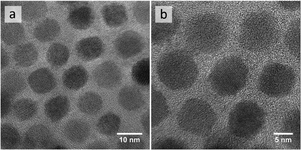 | ||
| Fig. 1 TEM images of as-synthesized oleate-capped PbTe NCs, illustrating their size distribution (a) and crystalline structure (b). | ||
Template-directed self-organized 3D micropillars
Conceptually, 3D micropillars can be produced via a straightforward process (Fig. 2a): deposition of concentrated NC dispersions onto pre-patterned Si wafers with resist-grid motifs and subsequent resist pattern removal. The result of a poor deposition (Fig. S5†), however, serendipitously illustrates the importance of carefully optimizing the corresponding protocol. First, the clean pre-patterned Si surface needs to be modified to promote the accumulation of PbTe NCs within the cavities of the resist grid: we found that MPTS modification provides a good balance between the simplicity of the modification procedure and the uniformity of the grid filling that it produces (Fig. 2b). The second critical parameter for producing 3D micropillars that have a uniform flat-top morphology is highlighted by observing various defective variants (concave, cracked, and partially filled) as a function of the NC concentration (Fig. S5†).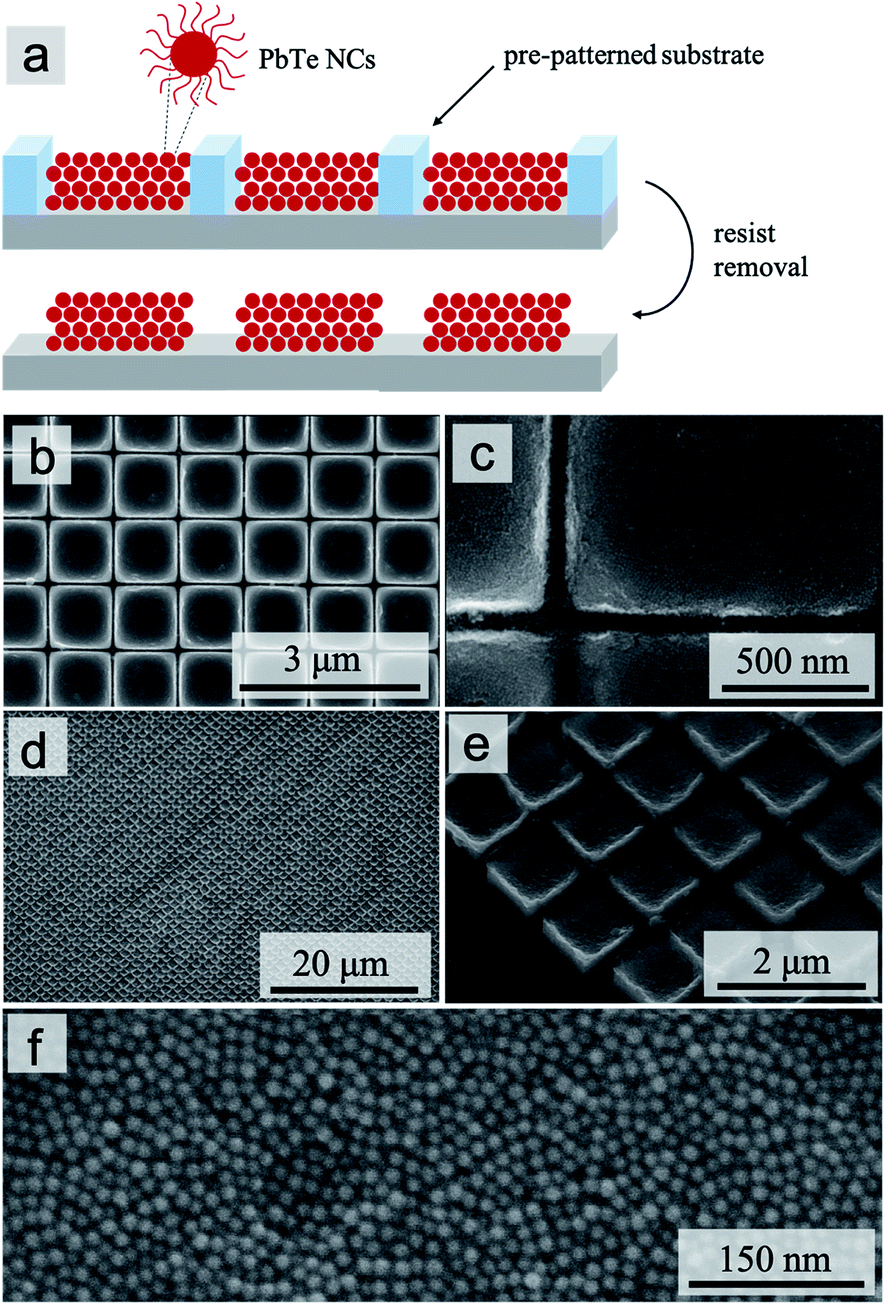 | ||
| Fig. 2 Template-directed self-organization of 3D micropillars. Schematic illustration of the process (a); SEM images of micropillar arrays with top (b and c) and 35°-tilted (d and e) views; high-magnification close-up of the top surface of a micropillar (f). | ||
The dense and stable packing of the NCs in the micropillar structures (Fig. 2f) is confirmed by observing that their full 3D shapes, including the 1 × 1 μm2 footprint (Fig. 3) and the flat-top (Fig. 3c) or defective morphology (Fig. 3a, b and S6b, c†), are preserved after the resist pattern removal and sonication (Fig. 3 and S6†). In other words, despite using NCs with a surface functionalization that explicitly only promotes their colloidal stability in suspension, the solvent evaporation process produces close-packed structures without having to modify the surface chemistry of the NCs.
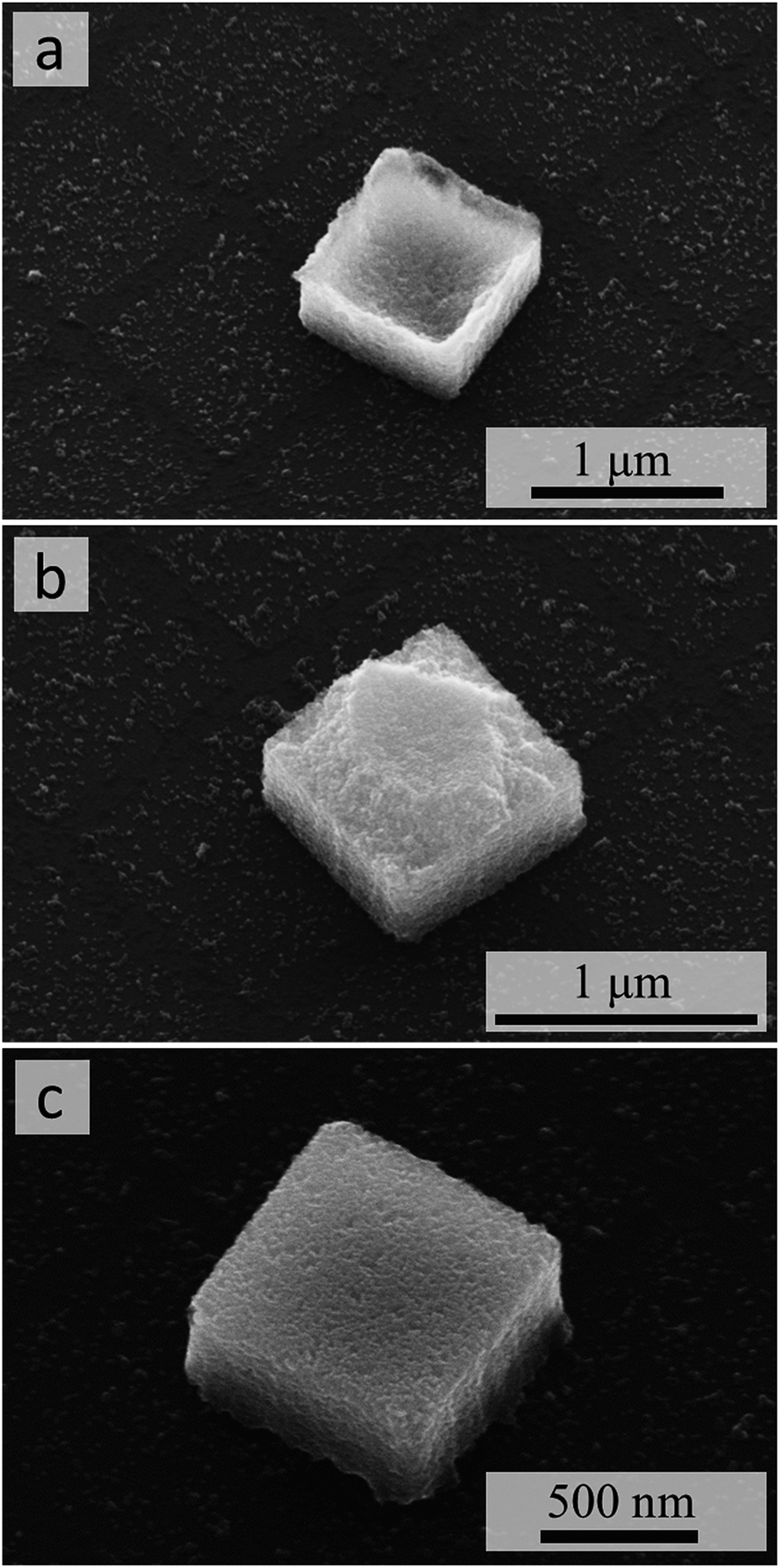 | ||
| Fig. 3 SEM images of individual micropillars after resist removal and sonication. The 35°-tilted view reveals top surfaces with concave (a), convex or “ragged edge” (b), or flat (c) morphologies. | ||
The top surface morphologies of the micropillars are clearly related to the “filling” of the resist-grid template by the NC dispersion. To produce such 3D filling, i.e., deposition of more than a few layers of NCs, the use of a slowly evaporating solvent (toluene in our case) is critical. The exact filling of the 3D templates, in turn, is controlled by a combination of the substrate surface chemistry (and any modification thereof), which enables the NC suspension to wet uniformly the 3D cavities of the template, and the concentration of NCs, which determines the total amount of NCs deposited into each 3D cavity. When that amount is insufficient to fill the cavity, the concave morphology of the top surface (Fig. 3a and S6b†) is produced. Conversely, an excessive amount of NCs “spills” over the walls of the template and forms a thin film of NCs across those walls: breaking of such “bridges” during the resist removal and sonication then produces the roughly convex or “ragged edge” morphology of the top surface (Fig. 3b and S6c†).
Finally, small alignment defects evident in both close-up (Fig. 2c and e) and overview (Fig. 2d) SEM images are primarily associated with the mechanical disruption during the resist removal and sonication steps. In device applications where a higher accuracy of alignment may be required, the 3D template cavities will not be defined only by the photoresist, but rather by the patterned solid substrate. Using such a model template (e.g., Fig. S4†), however, would not have allowed us to inspect the quality of the lateral confinement of the 3D micropillars, hence our choice of the resist grids for producing the model structures in Fig. 2 and 3.
Conformal NC coatings
The micropatterned substrates (Fig. 4a–c) were used to demonstrate the protocol for preparing conformal NC coatings, using the same batch of model NCs as in the previous example of 3D micropillars (Fig. 2 and 3). To produce thin conformal coatings instead of 3D microstructures, we reduced the concentration of NCs and switched to a faster evaporating solvent (hexane). The high-resolution SEM images in Fig. 4d–f clearly demonstrate that this protocol produces the desired close-packed NC coatings that conform to the 3D shapes of the micropatterned substrates. In particular, the continuous coatings achieved across the pattern boundaries with a wide range of radii of the curvature (from straight lines to sharp corners) demonstrate that the submicron topographical features of the template do not interfere with the formation of the conformal coatings, e.g., via edge effects in the evaporating meniscus. These close-packed thin layers of NCs should be suitable for applications that rely on proximal interactions between the NCs.24,29,30 Uniform conformal coatings over the entire microstructured surface could be useful in optical31 or energy32 applications. Alternatively, the coating outside of the patterned cavities could be removed, e.g., by using a strong tape, for applications where a thin continuous NC coating is needed only inside the micropatterned areas. | ||
| Fig. 4 SEM images of Si wafers with patterned microstructures of different shapes: stars (a), squares (b), and circles (c). High-magnification SEM images of conformal coatings prepared on the respective micropatterned templates after deposition of PbTe NCs (d–f). | ||
Self-supported NC membranes
In contrast to the conformal NC coatings in Fig. 4, producing the self-supported membranes of the same NCs over the same type of patterned substrates required an additional transfer step. Specifically, membranes of PbTe NCs were first assembled on the surface of diethylene glycol (DEG) (Fig. 5a) and then transferred onto the micropatterned silicon substrates (Fig. 5b and c). In this protocol, the surface of DEG effectively acted as a flat substrate for forming a very thin NC membrane upon the slow evaporation of the hexane solvent.22 The nearly dry character of the NC membrane formed on DEG is indicated by the absence of drying artifacts, such as cracks or wrinkles, upon the transfer of the membrane onto the micropatterned silicon substrates (Fig. 5d and e), which was followed by an additional overnight drying step at 70 °C to remove any residual DEG. The interactions between the close-packed NCs in the membrane that formed on the DEG surface thus produced a nearly dry but not brittle membrane, which is able to maintain its integrity during the transfer step: we did not observe any collapsed or cracked NC membranes. | ||
| Fig. 5 Fabrication of self-supported membranes: self-organization of PbTe NCs on DEG liquid surface (a); transfer of NCs onto micropatterned Si substrate (b and c). SEM images of self-supported membranes on Si substrates patterned with squares (d) and stars (e). | ||
After the final oven-drying step on the substrate, the self-supported NC membrane becomes more brittle and can be ruptured (Fig. S7†), confirming that these membranes are suspended above the voids of the micropatterned substrate.
Template-directed self-organization of PbTe NCs
Our systematic investigation of template-directed self-organization of model NCs into close-packed microstructured morphologies has explored a phase space of solvent-induced self-organization that fills the gap between the controlled deposition of individual nanoparticles9,28 onto micro- or nanostructured templates and formation of unstructured thin films from NCs.24,26,33 While some of the parameters, such as solvent and evaporation rate, are shared between our work and the template-directed deposition of individual nanoparticles, the underlying mechanisms exploited in such protocols typically are based on a match between the size of an individual particle, template dimensions, and the range of interactions between the particles and template features.9,28 In contrast, our protocols clearly rely on collective behavior of NCs interacting with the template features that are much larger than the individual NCs. This distinction is well illustrated by observing that the evaporating meniscus in our protocol determines the microscale shape of the resulting 3D solid (Fig. 3) rather than, for example, the position of one or a few particles within a microscale feature of a template.9,28 In other words, rather than attempting to control the positioning of individual particles, our protocols focus on using the micropatterned templates and solvent evaporation to direct the self-organization of NCs in a more hierarchical sense, allowing us to switch the final morphology from a rigid flat NC membrane (Fig. 5), to a conformal NC coating of a comparable thickness of just a few NCs (Fig. 4), to an accumulation of a much larger number of NCs into well-defined 3D microstructures (Fig. 2 and 3c).Conclusions
We have successfully demonstrated the fabrication of well-defined 3D micropillars, conformal coatings, and self-supported membranes from high-quality spherical 10 nm PbTe NCs by employing self-organization of NCs directed by micropatterned Si substrates. We have systematically investigated solvent-induced template-directed self-organization of NCs in a regime characterized by an unusual combination of the template scale and NC size as well as the minimal control parameters. The three distinct morphologies of the close-packed NCs have been produced via adjustments of only two process parameters—solvent and NC concentration—and without requiring a fine-tuned surface functionalization of the NCs, beyond their as-synthesized colloidal stability. The overall simplicity and versatility of the protocols demonstrated in our work suggest their use in device applications where bottom-up self-organization of NCs needs to be integrated with top-down micro- or nanofabricated structures. To further explore the potential of the reported methodology, nanoimprinting onto pre-patterned surfaces and fabrication of self-organized 3D nanocrystal structures by co-deposition of two different types of NCs is the focus of our ongoing research.Conflicts of interest
There are no conflicts to declare.Acknowledgements
M. P. acknowledges a post-doctoral fellowship from INL. This work was supported by the UT-BORN-PT project (UTAP-EXPL/CTE/0050/2017) funded by FCT, the PrintPV project (PTDC/CTM-ENE/5387/2014) co-funded by FCT and ERDF COMPETE 2020 funds, and the CritMag project (PTDC/NAN-MAT/28745/2017) co-funded by FCT and POCI funds.References
- G. M. Whitesides and B. Grzybowski, Self-Assembly at All Scales, Science, 2002, 295, 2418–2421 CrossRef CAS PubMed.
- M. Grzelczak, J. Vermant, E. M. Furst and L. M. Liz-Marzán, Directed Self-Assembly of Nanoparticles, ACS Nano, 2010, 4, 3591–3605 CrossRef CAS PubMed.
- D. Wang, M. Hermes, R. Kotni, Y. Wu, N. Tasios, Y. Liu, B. de Nijs, E. B. van der Wee, C. B. Murray and M. Dijkstra, et al., Interplay between Spherical Confinement and Particle Shape on the Self-Assembly of Rounded Cubes, Nat. Commun., 2018, 9, 2228 CrossRef PubMed.
- Y. Cui, M. T. Björk, J. A. Liddle, C. Sönnichsen, B. Boussert and A. P. Alivisatos, Integration of Colloidal Nanocrystals into Lithographically Patterned Devices, Nano Lett., 2004, 4, 1093–1098 CrossRef CAS.
- A. Ziabari, M. Zebarjadi, D. Vashaee and A. Shakouri, Nanoscale Solid-State Cooling: A Review, Rep. Prog. Phys., 2016, 79, 95901 CrossRef PubMed.
- F. J. Himpsel, J. L. McChesney, J. N. Crain, A. Kirakosian, V. Pérez-Dieste, N. L. Abbott, Y.-Y. Luk, P. F. Nealey and D. Y. Petrovykh, Stepped Silicon Surfaces as Templates for One-Dimensional Nanostructures, J. Phys. Chem. B, 2004, 108, 14484–14490 CrossRef CAS.
- E. H. Lay, A. Kirakosian, J.-L. Lin, D. Y. Petrovykh, J. N. Crain, F. J. Himpsel, R. R. Shah and N. L. Abbott, Alignment of Liquid Crystals on Stepped and Passivated Silicon Templates Prepared in Ultrahigh Vacuum, Langmuir, 2000, 16, 6731–6738 CrossRef CAS.
- L. Xu, W. Ma, L. Wang, C. Xu, H. Kuang and N. A. Kotov, Nanoparticle Assemblies: Dimensional Transformation of Nanomaterials and Scalability, Chem. Soc. Rev., 2013, 42, 3114–3126 RSC.
- L. Jiang, X. Chen, N. Lu and L. Chi, Spatially Confined Assembly of Nanoparticles, Acc. Chem. Res., 2014, 47(10), 3009–3017 CrossRef CAS PubMed.
- Y. Wang, M. Zhang, Y. Lai and L. Chi, Advanced Colloidal Lithography: From Patterning to Applications, Nano Today, 2018, 22, 36–61 CrossRef CAS.
- S. Ni, L. Isa and H. Wolf, Capillary Assembly as a Tool for the Heterogeneous Integration of Micro- and Nanoscale Objects, Soft Matter, 2018, 14, 2978–2995 RSC.
- F. Juillerat, H. H. Solak, P. Bowen and H. Hofmann, Fabrication of Large-Area Ordered Arrays of Nanoparticles on Patterned Substrates, Nanotechnology, 2005, 16, 1311 CrossRef CAS.
- H. Celio, E. Barton and K. J. Stevenson, Patterned Assembly of Colloidal Particles by Confined Dewetting Lithography, Langmuir, 2006, 22, 11426–11435 CrossRef CAS PubMed.
- F. Fan and K. J. Stebe, Assembly of Colloidal Particles by Evaporation on Surfaces with Patterned Hydrophobicity, Langmuir, 2004, 20, 3062–3067 CrossRef CAS PubMed.
- G. Decher, J. D. Hong and J. Schmitt, Buildup of Ultrathin Multilayer Films by a Self-Assembly Process: III. Consecutively Alternating Adsorption of Anionic and Cationic Polyelectrolytes on Charged Surfaces, Thin Solid Films, 1992, 210–211, 831–835 CrossRef CAS.
- W. J. Dressick, K. J. Wahl, N. D. Bassim, R. M. Stroud and D. Y. Petrovykh, Divalent–Anion Salt Effects in Polyelectrolyte Multilayer Depositions, Langmuir, 2012, 28, 15831–15843 CrossRef CAS PubMed.
- N. D. Bassim, W. J. Dressick, K. P. Fears, R. M. Stroud, T. D. Clark and D. Y. Petrovykh, Layer-by-Layer Assembly of Heterogeneous Modular Nanocomposites, J. Phys. Chem. C, 2012, 116, 1694–1701 CrossRef CAS.
- N. Bassim, A. Herzing, W. Dressick, K. Wahl, D. Petrovykh, K. Fears, R. Stroud and T. Clark, Scanning Transmission Electron Microscopy (STEM) Tomography of Layer-by-Layer PAH/PSS-Au Nanocomposite Structures, Microsc. Microanal., 2011, 17, 1012–1013 CrossRef.
- M. Lisunova, N. Holland, O. Shchepelina and V. V. Tsukruk, Template-Assisted Assembly of the Functionalized Cubic and Spherical Microparticles, Langmuir, 2012, 28, 13345–13353 CrossRef CAS PubMed.
- J. P. Hoogenboom, C. Rétif, E. de Bres, M. van de Boer, A. K. van Langen-Suurling, J. Romijn and A. van Blaaderen, Template-Induced Growth of Close-Packed and Non-Close-Packed Colloidal Crystals during Solvent Evaporation, Nano Lett., 2004, 4, 205–208 CrossRef CAS.
- M. K. Choi, J. Yang, K. Kang, D. C. Kim, C. Choi, C. Park, S. J. Kim, S. I. Chae, T.-H. Kim and J. H. Kim, et al., Wearable Red-Green-Blue Quantum Dot Light-Emitting Diode Array Using High-Resolution Intaglio Transfer Printing, Nat. Commun., 2015, 6, 7149 CrossRef CAS PubMed.
- A. Dong, J. Chen, P. M. Vora, J. M. Kikkawa and C. B. Murray, Binary Nanocrystal Superlattice Membranes Self-Assembled at the Liquid-Air Interface, Nature, 2010, 466, 474–477 CrossRef CAS PubMed.
- T. Paik, H. Yun, B. Fleury, S.-H. Hong, P. S. Jo, Y. Wu, S.-J. Oh, M. Cargnello, H. Yang and C. B. Murray, et al., Hierarchical Materials Design by Pattern Transfer Printing of Self-Assembled Binary Nanocrystal Superlattices, Nano Lett., 2017, 17, 1387–1394 CrossRef CAS PubMed.
- M. Piotrowski, M. Franco, V. Sousa, J. Rodrigues, F. L. Deepak, Y. Kakefuda, N. Kawamoto, T. Baba, B. Owens-Baird and P. Alpuim, et al., Probing of Thermal Transport in 50 nm Thick PbTe Nanocrystal Films by Time-Domain Thermoreflectance, J. Phys. Chem. C, 2018, 122, 27127–27134 CrossRef CAS.
- G. Xu, J. Liu, B. Liu and J. Zhang, Self-assembly of Pt nanocrystals into three-dimensional superlattices results in enhanced electrocatalytic performance for methanol oxidation, CrystEngComm, 2019, 21, 411–419 RSC.
- W.-L. Ong, S. M. Rupich, D. V. Talapin, A. J. H. McGaughey and J. A. Malen, Surface Chemistry Mediates Thermal Transport in Three-Dimensional Nanocrystal Arrays, Nat. Mater., 2013, 12, 410 CrossRef CAS PubMed.
- J. E. Murphy, M. C. Beard, A. G. Norman, S. P. Ahrenkiel, J. C. Johnson, P. Yu, O. I. Mićić, R. J. Ellingson and A. J. Nozik, PbTe Colloidal Nanocrystals: Synthesis, Characterization, and Multiple Exciton Generation, J. Am. Chem. Soc., 2006, 128, 3241–3247 CrossRef CAS PubMed.
- Y. Yin, Y. Lu, B. Gates and Y. Xia, Template-Assisted Self-Assembly: A Practical Route to Complex Aggregates of Monodispersed Colloids with Well-Defined Sizes, Shapes, and Structures, J. Am. Chem. Soc., 2001, 123, 8718–8729 CrossRef CAS PubMed.
- C. Jiang, S. Markutsya and V. V. Tsukruk, Collective and Individual Plasmon Resonances in Nanoparticle Films Obtained by Spin-Assisted Layer-by-Layer Assembly, Langmuir, 2004, 20, 882–890 CrossRef CAS PubMed.
- B. P. Pichon, P. Louet, O. Felix, M. Drillon, S. Begin-Colin and G. Decher, Magnetotunable Hybrid Films of Stratified Iron Oxide Nanoparticles Assembled by the Layer-by-Layer Technique, Chem. Mater., 2011, 23, 3668–3675 CrossRef CAS.
- P. Kurt, D. Banerjee, R. E. Cohen and M. F. Rubner, Structural color via layer-by-layer deposition: layered nanoparticle arrays with near-UV and visible reflectivity bands, J. Mater. Chem., 2009, 19, 8920–8927 RSC.
- X.-Q. Bao, D. Y. Petrovykh, P. Alpuim, D. G. Stroppa, N. Guldris, H. Fonseca, M. Costa, J. Gaspar, C. Jin and L. Liu, Amorphous oxygen-rich molybdenum oxysulfide Decorated p-type silicon microwire Arrays for efficient photoelectrochemical water reduction, Nano Energy, 2015, 16, 130–142 CrossRef CAS.
- D.-K. Ko and C. B. Murray, Probing the Fermi Energy Level and the Density of States Distribution in PbTe Nanocrystal (Quantum Dot) Solids by Temperature-Dependent Thermopower Measurements, ACS Nano, 2011, 5, 4810–4817 CrossRef CAS PubMed.
Footnote |
| † Electronic supplementary information (ESI) available. See DOI: 10.1039/c9na00370c |
| This journal is © The Royal Society of Chemistry 2019 |