
 Open Access Article
 This Open Access Article is licensed under a
 Creative Commons Attribution 3.0 Unported Licence
ZnX2 mediated post-synthetic transformation of zero dimensional Cs4PbBr6 nanocrystals for opto-electronic applications†
Sumit Kumar
Sharma‡
a,
Swati
Mamgain‡
b,
Burhanuddin
Attarwala
b and
Aswani
Yella
 *ab
*ab
aCentre for Research in Nanotechnology and Science, Indian Institute of Technology Bombay, 400076, India. E-mail: aswani.yella@iitb.ac.in
bDepartment of Metallurgical Engineering and Materials Science, Indian Institute of Technology Bombay, 400076, India
First published on 8th May 2019
Abstract
Herein we demonstrate a facile approach for the synthesis of all inorganic cesium lead halide perovskite nanocrystal composites CsPbX3 (X = Cl, Br, I) with high quantum yield by post-synthetic modulation of zero dimensional Cs4PbBr6 nanocrystals with ZnX2 salts. The transformation of Cs4PbBr6 nanocrystals into CsPbBr3 takes place in two steps, the first step being the surface modification of the Cs4PbBr6 nanocrystals with Zn2+ ions and the second step being extraction of CsBr by the Zn2+ ions resulting in the formation of composite Cs4PbBr6/CsPbBr3 nanocrystals. The transformed composite nanocrystals were found to have a PL QY exceeding 90% and the shape of the nanocrystals also changed from hexagonal to cubic shaped. Owing to the highly ionic nature of the nanocrystals, complete anion exchange could be also realized using ZnI2 salt. In the case of the iodide post-treated samples, nanorods were obtained which exhibited bright red photoluminescence. Photodetectors based on the ZnI2 treated Cs4PbBr6 NCs were fabricated, and the photodetectors exhibited a high on/off ratio with a fast response time. The excellent optoelectronic properties make this treatment versatile for a wide range of functional optoelectronic devices like light emitting diodes and photovoltaic devices.
Introduction
Lead halide perovskite NCs (especially CsPbX3 where X = Cl, Br, I) have received massive attention in recent years as favorable optoelectronic materials due to their broad absorption,1 intense photoluminescence (PL),1 high photoluminescence (PL) quantum yield (QY),2 very narrow emission line width,3 high defect tolerance,4 and wide-range band gaps which can be tuned by controlling the composition5,6 and morphology.7,8 Due to these interesting properties exhibited by the lead halide perovskite NCs they have been examined in the context of their use in optoelectronic devices, such as photovoltaics,9,10 light emitting diodes,11–15 lasers16 and photodetectors.17 In the recent past, numerous other types of cesium lead halide NCs, with structural dimensionality different from the three dimensional orthorhombic/cubic CsPbX3 have gained a lot of attention.18–25 The structural dimensionality in these structures depends on the extent of coupling of PbX6 octahedra in the crystal. If all the corners of the lead hexahalide octahedra are shared, then they are electronically coupled in all three dimensions and referred to as 3D perovskites. If all the corners of the lead hexahalide octahedra are not shared, they are referred to as 0D perovskites.25It is extensively recognized that the excellent optical properties in lead halide based perovskite materials come from the high defect tolerance.4 Even the highly luminescent perovskite NCs prepared by the hot injection method are really not defect-free, and these defects serve as trapping centers for exciton recombination and decrease the photoluminescence quantum yields (PLQYs) of the NCs.26–33 Different groups have recently synthesized 0D colloidal Cs4PbBr6 NCs and it has been found that these nanocrystals don't exhibit any photoluminescence.25 However, the non-luminescent 0D Cs4PbBr6 NCs can be converted to 3D CsPbBr3 NCs using additives like water,34 PbBr2![[thin space (1/6-em)]](https://www.rsc.org/images/entities/char_2009.gif) 35 ligands,36 and Prussian blue.37 The non-luminescent nature of Cs4PbBr6 at room temperature is attributed to the origin of structural and point defects.38 Nikl et al. observed the true emission of Cs4PbBr6 at low temperatures (4 K) and the true emission is centered at 375 nm. In the case of thin films at room temperature, Cs4PbBr6 is mixed with traces of the CsPbBr3 phase, which in turn results in the emission at 545 nm. However in the case of nanocrystals, no emission has been observed so far for the pure Cs4PbBr6 nanocrystals.
35 ligands,36 and Prussian blue.37 The non-luminescent nature of Cs4PbBr6 at room temperature is attributed to the origin of structural and point defects.38 Nikl et al. observed the true emission of Cs4PbBr6 at low temperatures (4 K) and the true emission is centered at 375 nm. In the case of thin films at room temperature, Cs4PbBr6 is mixed with traces of the CsPbBr3 phase, which in turn results in the emission at 545 nm. However in the case of nanocrystals, no emission has been observed so far for the pure Cs4PbBr6 nanocrystals.
Recently it has been shown that addition of appropriate metal halide salts significantly enhances the photoluminescence intensity of CsPbBr3 nanocrystals by improving the surface capping. Herein we demonstrate ZnX2 mediated post-synthetic transformation of Cs4PbBr6 nanocrystals (NCs) into CsPbX3 nanostructures through an intermediate composite Cs4PbX6/CsPbX3. We find that this procedure results in a highly reproducible increase of the PL QY of up to 90% for the ZnX2 treatment. The transformation takes place through the surface passivation of Cs4PbBr6 nanocrystals with ZnX2 followed by anion exchange (in the case of ZnI2 and ZnCl2) resulting in the formation of an intermediate Cs4PbX6@CsPbX3 passivated by ZnX2 followed by the extraction of CsBr from the composite nanostructures. Interestingly, as soon the ZnX2 is added to the nanocrystals, excitonic absorption resulting from the Cs4PbBr6 particles passivated with ZnX2 is observed. This is the first time that the true emission of the Cs4PbX6 crystal structure in the nanocrystalline phase was observed at room temperature.
The Cs4PbBr6 nanocrystals were synthesized according to the hot injection strategy as described in the Experimental section. The Cs4PbBr6 nanocrystal dispersion in hexane is completely transparent and as shown in the TEM images in Fig. 1b–d, the pristine Cs4PbBr6 nanocrystals consist of hexagons of around 30 nm in size. The powder diffraction pattern indicated that the nanocrystals crystallized in the rhombohedral Cs4PbBr6 phase in the space group R3c.
 | ||
| Fig. 1 (a) X-ray diffraction patterns obtained of the pristine Cs4PbBr6 NCs. (b–d) TEM images of the pristine Cs4PbBr6 NCs at different magnifications. | ||
The pristine Cs4PbBr6 nanocrystals (NCs) were post treated with a ZnX2/hexane solution and used for further characterization. Upon addition of ZnX2 (X= Cl, Br, I) solution, clear color change was observed (Fig. 2a). And the initially non-luminescent solution turned into a brightly luminescent solution under UV light after the post-treatment (Fig. 2b). To understand the reason for the observed color changes, powder diffraction analysis was carried out. Fig. 2c shows the X-ray diffraction patterns obtained for the pristine and ZnX2 treated NCs. The XRD pattern of the parent NCs indicated that they are crystalline and matched well with the reported rhombohedral Cs4PbBr6 phase. No characteristic reflections of CsPbBr3, CsBr or PbBr2 were observed. Upon treating with ZnBr2, new reflections were observed along with the reflections from Cs4PbBr6. All the new reflections could be attributed to the CsPbBr3 phase and the post treatment resulted in the formation of the composite Cs4PbBr6/CsPbBr3. Similar behavior was observed in the case of ZnI2 treated and ZnCl2 treated NCs wherein a composite of Cs4PbX6/CsPbX3 is formed. In the case of ZnI2 treated NCs, the pristine Cs4PbBr6 reflections were shifted towards the lower 2θ indicating that anion exchange took place from the bromide to iodide resulting in the formation of Cs4PbI6. A slight shift towards higher 2θ was observed in the case of ZnCl2 treated NCs. Interestingly, when the ZnX2 post treated solutions were left without centrifugation for a few days, the luminescence of the solution was reduced in comparison to that of the samples which were centrifuged and washed after the ZnX2 post-treatment. We have carried out XRD analysis on those samples left without centrifugation and Fig. 2d shows the diffraction patterns obtained for the same samples. From the diffraction patterns it can be seen that the ZnBr2 left in the solution results in the complete transformation of 0D Cs4PbBr6 NCs into 3D CsPbBr3 NCs. In the case of ZnI2 post-treatment, the reflections from 0D Cs4PbI6 still exist, indicating that the transformation from 0D to 3D is not complete even after a few days.
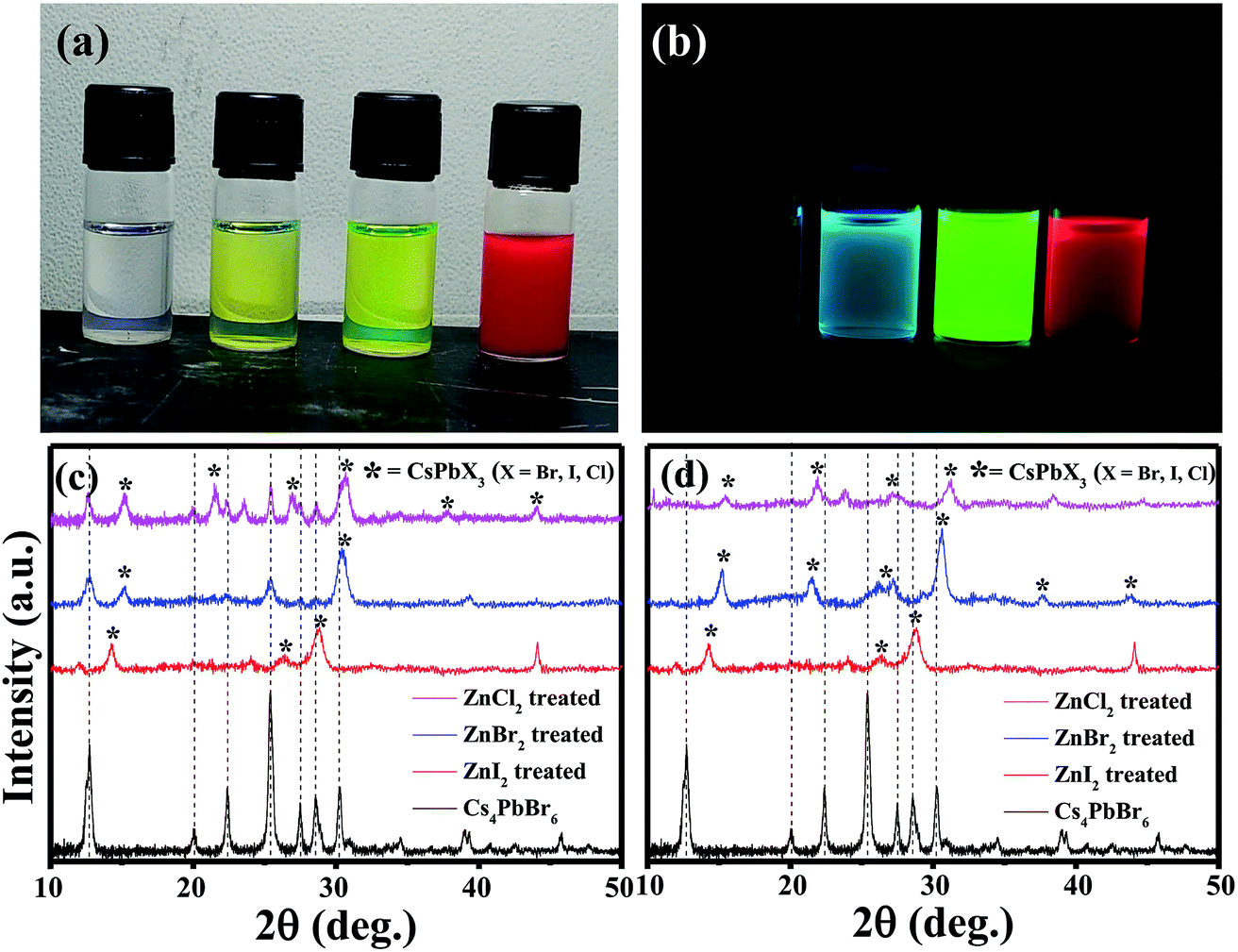 | ||
| Fig. 2 Photographs of the solutions of Cs4PbBr6, ZnCl2 treated, ZnBr2 treated and ZnI2 treated NCs, respectively under ambient light (a) and under UV light (b). (c) X-ray diffraction patterns obtained for the pristine and ZnX2 treated NCs. (d) X-ray diffraction patterns obtained of the samples left without centrifugation after the addition of ZnX2. | ||
The absorption spectra of the ZnX2 treated Cs4PbBr6 NCs are shown in Fig. 3a. For the pristine nanocrystals, the absorption and the photoluminescence features are consistent with those in the previously reported studies. The absorption spectra of the as-prepared nanocrystals feature a strong and narrow absorption at 313 nm. The long tail in the absorption spectrum indicates that a certain degree of coupling exists between the PbBr6 octahedra. Fig. 2a and b show the photographs of the pristine Cs4PbBr6 and ZnX2 treated NCs under room light and UV light. Upon treating the NCs with the ZnBr2/hexane solution, the initially colorless solution turned green color. The same is observed in the UV-vis absorption spectrum with a red shift of the absorption band edge to 510 nm. The features are similar to the characteristic feature of the 3D CsPbBr3 NCs,1–10 probably indicating the transformation of Cs4PbBr6 into CsPbBr3 NCs. Along with this, another hump was observed at 420 nm in the ZnBr2 treated sample. This hump was not observed previously in the pure CsPbBr3 NCs,1–10 the ZnBr2 stabilized CsPbBr3 NCs and the Zn2+ doped CsPbBr3 nanocrystals.39 To see if similar behavior is observed with other zinc halides, the Cs4PbBr6 NCs were also treated with ZnI2 and ZnCl2. ZnCl2 treatment resulted in a slight blue shift in comparison to ZnBr2 treated NCs. However, in the case of ZnCl2 treated NCs, no hump in the absorption spectrum was evident. In the case of ZnI2, an increased red shift (up to 670 nm) in comparison to that in the ZnBr2 treatment was observed. Along with the red shifted absorption, a sharp peak at 550 nm can be seen.
 | ||
| Fig. 3 (a) UV-vis absorption spectra of the ZnX2 treated Cs4PbBr6 nanocrystals. (b) Absorption spectra measured using different concentrations of the ZnBr2/hexane solution. (c) Absorption spectrum of ZnI2 treated NCs with the different concentrations of the ZnI2/hexane solution. (d) PL spectra of the pristine NCs and ZnBr2 treated NCs. PL spectra of the Cs4PbBr6 NCs with different concentrations of (e) ZnBr2 solution and (f) ZnI2 solution. | ||
To confirm if the peak observed at 420 nm arises from the sample, an aliquot of the Cs4PbBr6 NCs was taken in a cuvette, different concentrations of ZnBr2 were added to the sample and the absorption spectrum of the ZnBr2 treated NCs was measured. Fig. 3b shows the absorption spectra measured using different concentrations of the ZnBr2/hexane solution added to the cuvette containing NCs. A sharp absorption peak at 425 nm along with a long tail extending up to 510 nm was observed. The absorption intensity of the tail increased gradually and a sharp band edge at 510 nm, which is a characteristic peak of CsPbBr3, was observed. The peak at 425 nm is blue shifted to 420 nm and is masked (though visible) by the strong absorption of CsPbBr3 in this region. Fig. S1† shows the comparison of the absorption spectra of the CsPbBr3 nanocrystals synthesized and the ZnBr2 treated Cs4PbBr6 NCs. A similar concentration dependent study was carried out in the case of ZnI2 treated Cs4PbBr6 NCs. Fig. 3c shows the evolution of the absorption spectrum of ZnI2 treated NCs with different amounts of ZnI2 added. A sharp absorption at 540 nm is evident even with high amounts of added ZnI2. ZnBr2 treated NC samples were found to be highly stable even after 2 months of maintaining under 70% RH conditions. Fig. S2† shows photographs under UV light for the ZnBr2 treated NC sample and the as-prepared CsPbBr3 NCs after storing under 70% RH conditions.
To corroborate the observed absorption behavior, photoluminescence (PL) studies were also carried out on the parent NCs and ZnX2 treated NCs. Fig. 3d shows the PL spectra of the pristine NCs and ZnBr2 treated NCs. No strong PL emission was observed, which is consistent with the previously observed decay of excitonic PL above temperatures of 100 K. Very weak PL emission centered at 515 nm was observed which can be attributed to the CsPbBr3 phase embedded in the PL-inactive Cs4PbBr6 crystalline matrix. With the ZnBr2 post-treated NC solution, strong PL was observed at 518 nm. From the literature, it is known that the excitonic absorption peak of pure CsPbBr3 NCs is located at around 510 nm. So, it is reasonable to speculate that the strong excitonic absorption peak and strong PL peak at 518 nm in Fig. 3d originate from the CsPbBr3 NCs, indicating that a transformation might have taken place from Cs4PbBr6 to CsPbBr3.
We also carried out ZnBr2 concentration dependent emission studies. With the addition of ZnBr2, two emission peaks were observed, one at 430 nm and the other at 510 nm, similar to the behavior observed in the absorption spectrum. The emission at 430 nm could be attributed to the 425 nm peak observed in the absorption spectrum and the peak at 510 nm could be attributed to the band edge emission corresponding to the absorption edge shown in Fig. 3e. Similar behavior was also observed in the case of the iodide counterpart, wherein the two emission peaks corresponds to the absorption peak at 550 nm and band edge absorption (Fig. 3f).
Together with the results obtained from the XRD studies and UV-vis and PL spectra, we speculate that CsPbX3/Cs4PbX6 composites were formed after the post-treatment with ZnX2. In the case of ZnBr2, the excitonic CsPbBr3 absorption was observed at 510 nm and the absorption peak observed at a lower wavelength could be attributed to the Cs4PbBr6 phase. It has been previously reported that defect states created due to the surface halide vacancies could be responsible for quenching the true emission in Cs4PbBr6 and were only observed at low temperatures (4 K). When the Zn2+ salts were added to the Cs4PbBr6 NCs, the surface halide defect states could be passivated and the true emission from the surface passivated/modified Cs4PbBr6 nanocrystals could be observed at 430 nm. The true emission of Cs4PbBr6 is observed for the first time at room temperature when Zn2+ salts are used to passivate the surface defects; however, the Zn2+ salts also triggered the transformation of 0D Cs4PbBr6 NCs into 3D CsPbBr3 NCs. So, the intensity of the true emission of Cs4PbBr6 NCs gradually decreased as the concentration of the zinc salt is increased. When the concentration of the zinc salt was kept constant at 50 μL of ZnBr2, the intensity gradually decreased indicating that the whole process takes place through a two-step mechanism. Similar studies carried out using other salts like Cu2+ and Mn2+ didn't result in the enhancement of the PL QY. In the case of Mn2+ a slight increase was observed but Cu2+ didn't show any improvement in the PL QY. Fig. S3† shows the PL of the CuBr2 and MnBr2 treated Cs4PbBr6 NCs.
TEM images of the as-synthesized Cs4PbBr6 NCs show hexagonal shaped particles of around 30–35 nm in size similar to the particles reported previously. Fig. 4 shows the TEM images of the as-synthesized Cs4PbBr6 NCs and the ZnBr2 treated samples. When the samples were treated with 50 μL of ZnBr2, initially hexagonal shaped particles were converted mostly to cubic shaped particles as shown in Fig. 4. More than 90% of the particles became cubic; however the cubic shaped particles did not have sharp edges as observed in the case of the as-prepared CsPbBr3 NCs (Fig. S4†). The HR-TEM image (Fig. 4d) shows a lattice spacing of 0.58 nm for the (100) plane of CsPbBr3 after ZnBr2 treatment. The edges of the particles, however, show that the lattice spacing is not the same as that in the center of the particles. The lattice spacing of 0.33 nm for the (411) plane corresponds to the presence of Cs4PbBr6, indicating the formation of a composite of CsPbBr3/Cs4PbBr6. A plausible two step formation mechanism can be inferred from the observed TEM images. As the Cs4PbBr6 nanocrystals were treated with the zinc halide salts, in the first step Zn2+ ions could passivate the surface of the nanocrystals and then result in the extraction of excess Cs+ ions, and an increase in the dimensionality from 0D to 3D is observed. In the second step we believe that an inside out diffusion of Cs+ ions takes place resulting in the formation of CsPbBr3/Cs4PbBr6 composites.
 | ||
| Fig. 4 TEM images of the ZnBr2 treated Cs4PbBr6 NC samples (a–c) and HRTEM (d) image of the ZnBr2 treated Cs4PbBr6 NC samples indicating the formation of a composite of CsPbBr3/Cs4PbBr6 NCs. | ||
When the Cs4PbBr6 NCs were treated with 40 μL of ZnI2 solution, the shape of the particles changed from hexagonal to rod shaped. As seen in the TEM images shown in Fig. 5b the corners of the rods still have hexagonal facets. With the increase in the concentration of the ZnI2 solution to 100 μL the length of the rods increased to nearly 250 nm and the width increased to 20–30 nm.
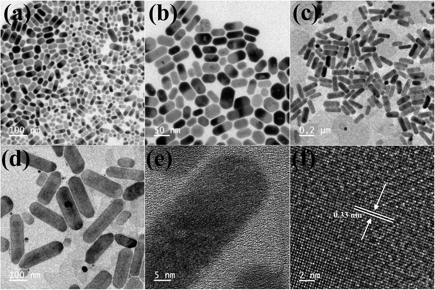 | ||
| Fig. 5 TEM images obtained after the 40 μL ZnI2 post treatment (a and b) and 100 μL ZnI2 post treatment (c–f). HRTEM images showing the lattice spacing after the post treatment with 100 μL ZnI2 (e and f). | ||
To see if any zinc is present on the surface of the nanocrystals, resulting in the enhanced PL QY, X-ray photoelectron spectroscopy (XPS) measurements have been used to assess the surface modification of the NCs and to understand the mechanism of PL enhancement. After measurements, all core level spectra were calibrated using the C 1s peak at 285.0 eV. The high-resolution XPS spectrum of untreated NCs for Pb 4f yields 2 peaks as shown in Fig. S5.† Two intense peaks are observed at 138 eV (4f7/2) and 143 eV (4f5/2) with a spin–orbit splitting of nearly 5 eV, which corresponds to Pb in the 2+ oxidation state. Quantitative XPS analysis indicates that Cs:Pb:Br = 1.5:1:4.2 for untreated Cs4PbBr6 NCs, which is Pb rich in composition. However, for ZnBr2-Cs4PbBr6 NCs, the composition becomes anion-rich (Cs:Pb:Br = 0.6:1:5.5), which was also repeatedly observed (Fig. S6†). A small fraction of the Zn2+ was also observed in the ZnBr2 treated Cs4PbBr6 NCs, with the ratio of Pb:Zn = 1:0.08. This also conforms with the previous observations that the Zn2+ ions modify the surface of the nanocrystals, which then results in the extraction of excess Cs+ ions from the Cs4PbBr6 NCs. Furthermore, the Pb/Cs ratio increased from 0.66 to 1.66 in ZnBr2 treated Cs4PbBr6 NCs compared with pristine-Cs4PbBr6 NCs indicating that ZnBr2 extracted excess Cs+ ions present. This is also consistent with the XRD analysis wherein the Cs4PbBr6 is converted to CsPbBr3 after the extraction of cesium ions. We have also carried out XPS analysis of the ZnI2 treated Cs4PbBr6 NCs and found that the ratio of Pb:Zn (1:0.15) is much higher compared to that in the bromine case (Fig. S7†).
Owing to the one-dimensional nature of the nanorods in the case of ZnI2 treated Cs4PbBr6 NCs, we have explored their potential application in optoelectronic devices. To this end, we have fabricated photodetectors by dropcasting the ZnI2 treated NCs in hexane between two fluorine doped tin oxide (FTO) electrodes. Fig. 6a shows the schematic of the device architecture that is employed for the fabrication of the devices. The dark current observed was in the order of a few picoamperes, within the detection limit of our instrument. The current of the same device increased under illumination using a diode source of 617 nm, demonstrating their potential as an efficient photodetector. Fig. 6b shows the IV curves obtained in the dark and in the presence of the light diodes. The ratio of the photocurrent to dark current could reach over two orders of magnitude. Time-dependent photocurrent measurements were carried out by pulsing the diode at a fixed light intensity with an applied bias voltage of 2 V. Prompt and reproducible photocurrent response to the pulsing was observed indicating the excellent optical switching and stability of the photodetectors. The rise time and decay time were also determined from the pulsing experiments and they are in the order of a few milliseconds as shown in Fig. 6d. When the photodetectors were fabricated using ZnBr2 treated nanocrystals, the currents obtained were lower compared to those using the ZnI2 treated samples. Fig. S8† shows the performance of the photodetectors using ZnBr2 treated NCs in the same configuration. This indicates that the performance of the photodetectors could be improved if the length of the nanorods could be made longer than the width of the channel used and also by removing the surface capping ligands by appropriate treatments.
 | ||
| Fig. 6 (a) Schematic of the photo-detector architecture. (b) I–V curves in the dark and in the presence of 617 nm light. (c) Photocurrent time characteristics of the photo detector in the dark and under light (617 nm, 1 volt). (d) Rise and decay time. | ||
In conclusion, we have developed a simple and convenient post synthetic strategy for the transformation of 0D Cs4PbBr6 into highly luminescent CsPbBr3/Cs4PbBr6 composites using ZnBr2 treatment. The transformation with ZnBr2 treatment proceeds through a two-step process, where in the first step, zinc doped/modified Cs4PbBr6 NCs are formed which then results in the conversion to CsPbBr3/Cs4PbBr6 nanocomposites. The composite of CsPbBr3/Cs4PbBr6 NCs is found to be very highly luminescent with a PL QY of 90%. In the case of ZnI2 treatment, the post synthetic treatment also resulted in morphological transformation from the hexagonal shaped nanocrystals to nanorods. The length of the rods could be varied depending on the concentration of the nanocrystals and the zinc iodide salt added. In both the iodide and bromide case an intermediate is formed upon treatment with the zinc salt. The intermediate was observed in the time/concentration dependent UV-vis and PL studies, and from the X-ray diffraction analysis, we presume that it is the 0D structure modified/doped by the zinc cations. Photodetectors based on the ZnI2 treated Cs4PbBr6 NCs were fabricated, which exhibit a high on/off ratio with a fast response time. The excellent optoelectronic properties make this treatment versatile for a wide range of functional optoelectronic devices like light emitting diodes and photovoltaic devices.
Experimental section
Chemicals
Cesium carbonate (Cs2CO3, 99.9%), lead(II) bromide (98%), zinc(II) iodide (98%), zinc(II) chloride (99%), oleylamine (OLA, 70%), oleic acid (90%), and 1-octadecene (90%) were purchased from Sigma Aldrich. Zinc(II) bromide (98%) was purchased from Alfa Aesar.Synthesis of cesium oleate
Cesium carbonate (Cs2CO3, 160 mg), oleic acid (1 mL), and octadecene (16 mL) were added to a three-neck flat bottom flask and kept under vacuum for 30 min at 120 °C. After 30 minutes the temperature was increased to 150 °C and the system was kept under a N2 atmosphere until a clear solution of cesium oleate was obtained.Synthesis of Cs4PbBr6 nanoparticles
Octadecene (10 mL), oleylamine (1 mL), oleic acid (1 mL) and lead bromide (0.36 mmol, 73.4 mg) were loaded into a three-neck round bottom flask and degassed for 30 min at 120 °C. The flask was then filled with N2 and the temperature was increased to 140 °C. After that, 4.4 mL of hot cesium oleate solution was injected quickly. After 5 s, the reaction mixture was quenched in an ice-water bath.Synthesis of CsPbBr3 nanoparticles
Lead bromide (207 mg) and octadecene (15 mL) were loaded into a three-neck round bottom flask and degassed for 1 hour at 120 °C. The flask was then filled with N2 and oleylamine (1.5 mL) and oleic acid (1.5 mL) were added. After complete solubilisation of PbBr2, the temperature was increased to 165 °C and finally the as-prepared Cs-oleate (1.2 mL) was injected. The reaction was immediately quenched in an ice-water bath.Purification of nano particles
The crude solution of nanoparticles was first centrifuged at 6000 rpm for 10 min. After that, the supernatant was discarded and the precipitate was redispersed in hexane solution. Then again, the large particles present in the solution were removed by centrifugation at 6000 rpm for 10 min. The supernatant was discarded and a colloidal solution of nanoparticles was obtained in hexane.ZnX2 (X = Br, I and Cl) treatment
The NCs dispersed in hexane (∼8 mg mL−1) were treated with the pre-made zinc halide solution. Zinc halide solutions were prepared by dissolving zinc halides (ZnX2, X= I, Br, Cl) (0.05 M) in the mixture of hexane (2 mL) and oleylamine (40 μL) at room temperature. Then the required zinc halide solution was added to 1 mL of the Cs4PbBr6 NCs in hexane solution (8 mg mL−1) under constant stirring. Excess zinc halide salts are removed by centrifugation and the NCs can be stored in organic solvents like hexane, toluene, etc. for a few months.Characterization
High resolution transmission electron microscope images were obtained using a Tecnai G2 F30 300 kV transmission electron microscope. X-ray diffraction spectra were obtained by using a Rigaku Japan SmartLab X-ray diffractometer (Cu Kα, λ = 1.541). PL spectra were collected by using a Horiba FluoroMax spectrometer with 400 nm excitation wavelength, while UV-vis absorption measurement was performed using a UV-vis-NIR spectrometer (PerkinElmer LAMBDA 950). The room-temperature PLQY was calculated according to the following equation38
In this equation, QYsample is the PLQY of the sample. PLAreasample is the integrated emission spectrum curve area for the sample. Isample is the absorption value at the excitation wavelength for the sample. nsample is the refractive index of the employed solvent. QYref, PLArearef, Iref and nref are those for the standard reference respectively. In our experiment, fluorescein sodium salt in water and Rhodamine 6G in water (PLQY = 0.95) were chosen to be the standards for green and red spectral regions and the standard solutions should be freshly prepared. Attention was paid to keeping the optical densities of the sample and standard below 0.1 at the excitation wavelength.
Photodetector fabrication
Laser patterned FTO coated glass with an etched area was used as the photodetector. Before deposition, the laser patterned FTO was cleaned thoroughly by using a soap solution, DI water, acetone, and ethanol for 10 minutes, respectively, by ultra-sonication. Perovskite nanocrystals in hexane were drop cast on the etched area of the FTO coated glass by masking the unetched area with scotch tape. The drop cast substrate was then subjected to vacuum drying. Then the photoresponse was measured under a 617 nm LED light.Conflicts of interest
There are no conflicts to declare.Acknowledgements
This work was primarily supported by the Science and Engineering Research Board, Government of India, under grant number ECR/2016/000550. SKS acknowledges the National Center for Photovoltaic Research and Education (NCPRE) for the financial support and SM and BA acknowledge IIT-Bombay for the doctoral and masters fellowships, respectively. AY acknowledges the National Center for Photovoltaic Research and Education (NCPRE), IIT-Bombay for use of the facilities. The authors acknowledge the Central Surface Analytical Facility (ESCA) of IIT Bombay for XPS measurements.References
- L. Protesescu, S. Yakunin, M. I. Bodnarchuk, F. Krieg, R. Caputo, C. H. Hendon, R. X. Yang, A. Walsh and M. V. Kovalenko, Nano Lett., 2015, 15, 3692–3696 CrossRef CAS PubMed
.
- A. Swarnkar, R. Chulliyil, V. K. Ravi, M. Irfanullah, A. Chowdhury and A. Nag, Angew. Chem., 2015, 127, 15644–15648 CrossRef
- R. E. Brandt, V. Stevanović, D. S. Ginley and T. Buonassisi, MRS Commun., 2015, 5, 265–275 CrossRef CAS
- D. N. Dirin, L. Protesescu, D. Trummer, I. V. Kochetygov, S. Yakunin, F. Krumeich, N. P. Stadie and M. V. Kovalenko, Nano Lett., 2016, 16, 5866–5874 CrossRef CAS PubMed
- Q. A. Akkerman, V. D'Innocenzo, S. Accornero, A. Scarpellini, A. Petrozza, M. Prato and L. Manna, J. Am. Chem. Soc., 2015, 137, 10276–10281 CrossRef CAS PubMed
- G. Nedelcu, L. Protesescu, S. Yakunin, M. I. Bodnarchuk, M. J. Grotevent and M. V. Kovalenko, Nano Lett., 2015, 15, 5635–5640 CrossRef CAS PubMed
- Y. Bekenstein, B. A. Koscher, S. W. Eaton, P. Yang and A. P. Alivisatos, J. Am. Chem. Soc., 2015, 137, 16008–16011 CrossRef CAS PubMed
- D. Zhang, Y. Yu, Y. Bekenstein, A. B. Wong, A. P. Alivisatos and P. Yang, J. Am. Chem. Soc., 2016, 138, 13155–13158 CrossRef CAS PubMed
- A. Swarnkar, A. R. Marshall, E. M. Sanehira, B. D. Chernomordik, D. T. Moore, J. A. Christians, T. Chakrabarti and J. M. Luther, Science, 2016, 354, 92–95 CrossRef CAS PubMed
- Q. A. Akkerman, M. Gandini, F. Di Stasio, P. Rastogi, F. Palazon, G. Bertoni, J. M. Ball, M. Prato, A. Petrozza and L. Manna, Nat. Energy, 2017, 2, 16194 CrossRef CAS
- X. Zhang, H. Lin, H. Huang, C. Reckmeier, Y. Zhang, W. C. H. Choy and A. L. Rogach, Nano Lett., 2016, 16, 1415–1420 CrossRef CAS PubMed
- H. Huang, H. Lin, S. V. Kershaw, A. S. Susha, W. C. H. Choy and A. L. Rogach, J. Phys. Chem. Lett., 2016, 7, 4398–4404 CrossRef CAS PubMed
- F. Palazon, F. Di Stasio, Q. A. Akkerman, R. Krahne, M. Prato and L. Manna, Chem. Mater., 2016, 28, 2902–2906 CrossRef CAS PubMed
- X. Li, Y. Wu, S. Zhang, B. Cai, Y. Gu, J. Song and H. Zeng, Adv. Funct. Mater., 2016, 26, 2435–2445 CrossRef CAS
- J. Song, J. Li, X. Li, L. Xu, Y. Dong and H. Zeng, Adv. Mater., 2015, 27, 7162–7167 CrossRef CAS PubMed
- Y. Wang, X. Li, J. Song, L. Xiao, H. Zeng and H. Sun, Adv. Mater., 2015, 27, 7101–7108 CrossRef CAS PubMed
- P. Ramasamy, D.-H. Lim, B. Kim, S.-H. Lee, M.-S. Lee and J.-S. Lee, Chem. Commun., 2016, 52, 2067–2070 RSC
- X. Zhang, B. Xu, J. Zhang, Y. Gao, Y. Zheng, K. Wang and X. W. Sun, Adv. Funct. Mater., 2016, 26, 4595–4600 CrossRef CAS
- K.-H. Wang, L. Wu, L. Li, H.-B. Yao, H.-S. Qian and S.-H. Yu, Angew. Chem., Int. Ed., 2016, 55, 8328–8332 CrossRef CAS PubMed
- G. Li, H. Wang, Z. Zhu, Y. Chang, T. Zhang, Z. Song and Y. Jiang, Chem. Commun., 2016, 52, 11296–11299 RSC
- M. I. Saidaminov, J. Almutlaq, S. Sarmah, I. Dursun, A. A. Zhumekenov, R. Begum, J. Pan, N. Cho, O. F. Mohammed and O. M. Bakr, ACS Energy Lett., 2016, 1, 840–845 CrossRef CAS
- D. Chen, Z. Wan, X. Chen, Y. Yuan and J. Zhong, J. Mater. Chem. C, 2016, 4, 10646–10653 RSC
- Q. A. Akkerman, S. Park, E. Radicchi, F. Nunzi, E. Mosconi, F. De Angelis, R. Brescia, P. Rastogi, M. Prato and L. Manna, Nano Lett., 2017, 17, 1924–1930 CrossRef CAS PubMed
- J. Kang and L.-W. Wang, J. Phys. Chem. Lett., 2017, 8, 489–493 CrossRef CAS PubMed
- S. Seth, N. Mondal, S. Patra and A. Samanta, J. Phys. Chem. Lett., 2016, 7, 266–271 CrossRef CAS PubMed
- J. Y. Woo, Y. Kim, J. Bae, T. G. Kim, J. W. Kim, D. C. Lee and S. Jeong, Chem. Mater., 2017, 29, 7088–7092 CrossRef CAS
- N. K. Noel, A. Abate, S. D. Stranks, E. S. Parrott, V. M. Burlakov, A. Goriely and H. J. Snaith, ACS Nano, 2014, 8, 9815–9821 CrossRef CAS PubMed
- F. Di Stasio, S. Christodoulou, N. Huo and G. Konstantatos, Chem. Mater., 2017, 29, 7663–7667 CrossRef
- B. A. Koscher, J. K. Swabeck, N. D. Bronstein and A. P. Alivisatos, J. Am. Chem. Soc., 2017, 139, 6566–6569 CrossRef CAS PubMed
- J. Pan, Y. Shang, J. Yin, M. De Bastiani, W. Peng, I. Dursun, L. Sinatra, A. M. El-Zohry, M. N. Hedhili, A.-H. Emwas, O. F. Mohammed, Z. Ning and O. M. Bakr, J. Am. Chem. Soc., 2018, 140, 562–565 CrossRef CAS PubMed
- G. Rainò, G. Nedelcu, L. Protesescu, M. I. Bodnarchuk, M. V. Kovalenko, R. F. Mahrt and T. Stöferle, ACS Nano, 2016, 10, 2485–2490 CrossRef PubMed
- L. Wu, H. Hu, Y. Xu, S. Jiang, M. Chen, Q. Zhong, D. Yang, Q. Liu, Y. Zhao, B. Sun, Q. Zhang and Y. Yin, Nano Lett., 2017, 17, 5799–5804 CrossRef CAS PubMed
- Z. Liu, Y. Bekenstein, X. Ye, S. C. Nguyen, J. Swabeck, D. Zhang, S.-T. Lee, P. Yang, W. Ma and A. P. Alivisatos, J. Am. Chem. Soc., 2017, 139, 5309–5312 CrossRef CAS PubMed
- F. Palazon, G. Almeida, Q. A. Akkerman, L. De Trizio, Z. Dang, M. Prato and L. Manna, Chem. Mater., 2017, 29, 4167–4171 CrossRef CAS PubMed
- F. Palazon, C. Urso, L. De Trizio, Q. Akkerman, S. Marras, F. Locardi, I. Nelli, M. Ferretti, M. Prato and L. Manna, ACS Energy Lett., 2017, 2, 2445–2448 CrossRef CAS PubMed
- M. Nikl, E. Mihokova, K. Nitsch, F. Somma, C. Giampaolo, G. P. Pazzi, P. Fabeni and S. Zazubovich, Chem. Phys. Lett., 1999, 306, 280–284 CrossRef CAS
- W. van der Stam, J. J. Geuchies, T. Altantzis, K. H. W. van den Bos, J. D. Meeldijk, S. Van Aert, S. Bals, D. Vanmaekelbergh and C. de Mello Donega, J. Am. Chem. Soc., 2017, 139, 4087–4097 CrossRef CAS
- H. Duan, Y. Jiang, Y. Zhang, D. Sun, C. Liu, J. Huang, X. Lan, H. Zhou, L. Chen and H. Zhong, Nanotechnology, 2013, 24, 285201 CrossRef PubMed
- W. Stam, J. J. Geuchies, T. Altantzis, K. H. W. van den Bos, J. D. Meeldijk, S. Van Aert, S. Bals, D. Vanmaekelbergh and C. de Mello Donega, J. Am. Chem. Soc., 2017, 139, 4087–4097 CrossRef
Footnotes |
| † Electronic supplementary information (ESI) available. See DOI: 10.1039/c9na00244h |
| ‡ Both the authors contributed equally. |
| This journal is © The Royal Society of Chemistry 2019 |