Preparation of synergistically reinforced transparent bio-polycarbonate nanocomposites with highly dispersed cellulose nanocrystals†
Seul-A
Park‡
 a,
Youngho
Eom‡
 a,
Hyeonyeol
Jeon‡
 a,
Jun Mo
Koo
 a,
Eun Seong
Lee
 b,
Jonggeon
Jegal
 a,
Sung Yeon
Hwang
 *ac,
Dongyeop X.
Oh
 *ac and
Jeyoung
Park
 *ac
*ac
aResearch Center for Bio-based Chemistry, Korea Research Institute of Chemical Technology (KRICT), Ulsan 44429, Republic of Korea. E-mail: crew75@krict.re.kr; dongyeop@krict.re.kr; jypark@krict.re.kr
bDepartment of Biotechnology, The Catholic University of Korea, Bucheon, Gyeonggi-do 14662, Republic of Korea
cAdvanced Materials and Chemical Engineering, University of Science and Technology (UST), Daejeon 34113, Republic of Korea
First published on 31st July 2019
Abstract
Polycarbonate (PC) is a transparent polymeric material which can replace shattering glass, but bisphenol-A, used for improving its properties, has controversial hazards. An alternative biomass-derived isosorbide (ISB)-based PC can be used owing to its complementary properties. To satisfy the two factors of sustainability and performance simultaneously, this paper proposes the in situ polymerization of ISB pre-dispersed with cellulose nanocrystals (CNCs), which directly produces PC nanocomposites, as a facile method for achieving record-high mechanical strength among all types of PCs and their nanocomposites. The proposed nanocomposite is more transparent, exhibits an ultimate tensile strength of 93 MPa and a 4.3-fold increased toughness of 40 MJ m−3, compared to a homo-polymer, and is better than post-blended nanocomposites due to the excellent dispersibility of 0.3 wt% nanofiller. Formidable improvements in in situ PC/CNC nanocomposites originate from the simultaneous contributions of covalent and physical interactions through polymeric grafting on the CNC surface and hydrogen bonding with a polar ISB moiety of PC, in advance, from the monomer dispersion, respectively, enhancing the interfacial interaction with the polymer matrix. This in situ approach opens new possibilities in the field of sustainable plastic industries.
Introduction
As compared to traditional glass, which shatters into dangerous pieces, transparent plastics provide significant benefits in our everyday lives. They have various applications, including their use in beverage bottles, lenses, protective shields, optical fibers, and display substrates.1–4 Polycarbonate (PC) is a best-selling transparent engineering plastic (EP), showing much higher thermal and mechanical performances than polystyrene and polymethylmethacrylate. As an inseparable partner, glass fiber, with a diameter of 3–20 μm, compliments the brittleness generally inherited by amorphous high-glass-transition-temperature (Tg) polymers, such as PCs.5However, PC/glass fiber composites pose health and environmental risks. Bisphenol-A (BPA) is a key diol monomer used for improving the mechanical/thermal properties and transparency of PCs due to its unique molecular structure. However, BPA causes developmental and reproductive problems in humans.6–8 Thus, PCs are being withdrawn from children's products and food packaging, such as nursing bottles. Meanwhile, glass fibers affect the health of workers.9 In the event of a fire or incineration, such inorganic particle-filled composites generate fine particulates, which can cause lung diseases because they are not pyrolyzed.
To address these problems, we designed a sustainable and transparent EP, a PC that not only utilizes a bio-derived monomer, i.e., isosorbide (ISB), instead of BPA, but is also reinforced with a bio-renewable organic filler, cellulose nanocrystals (CNCs). ISB and CNCs are promising renewable, robust building blocks and have a common lineage. Both are derived from glucose and have ether linkages. That is why they are highly miscible with each other, based on the principle of “like-dissolves-like”.
This study aims to maximize the reinforcing effects of CNCs with a minimal filler dose, which would be more sustainable without compromising transparency and production costs. Theoretically, nanofillers at only less than 1 wt% guarantee mechanical reinforcement for their homogeneous dispersion in a matrix, while up to 10–20 wt% micron-sized glass fibers are required.10 In fact, the various organic/inorganic nanofillers and differentiation strategies have been less effective at increasing the mechanical strength of EP (i.e., PC or polyester) nanocomposites with a minimal filler content.11–15 Unavoidable filler aggregation has discouraged the researchers. Moreover, a complex and sophisticated system is not preferred in the industry. Thus, there has not been much achievement in reducing the amount of fillers or enhancing the reinforcement.
In the case of inorganic nanofillers such as clay, layered double hydroxides, and carbon nanomaterials, significantly high contents exceeding 1 wt% are required for reinforcing effects considering the aggregated portions, because of the poor affinity between inorganic nanofillers and an organic polymer matrix.16–19 In this study, we did not use inorganic particles because of the aforementioned environmental reasons. In contrast, hydrophilic CNCs suffer from the issue of polarity with general hydrophobic polymer matrices.20–28 Moreover, it is more difficult to disperse CNCs within the matrix of glassy amorphous polymers with high Tg, to which most transparent EPs, including PCs, belong, because their high viscosity restricts mixing well.29 Therefore, mechanical enhancements by CNCs are only valid for relatively polar and flexible polymers such as polyurethanes and polyvinyl alcohols.30–32
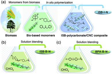
Herein, we begin from the well-dispersed CNCs in ISB liquid, and preserve a homogeneous CNC dispersion during our particular in situ condensation polymerization of the CNC/ISB monomer mixture (Fig. 1). The resultant plastic is considered to be the first transparent, sustainable, reinforced, and high-Tg EP nanocomposite. The hydrophilic surface of the CNC is chemically modified to carbonate linkages, spontaneously, which enhances the interfacial interaction with the polymer matrix to achieve superior mechanical performances, which has not been reported previously.
Results and discussion
In situ synthesis of bio-polycarbonate nanocomposites with nanocellulose
Recent effort in developing high-Tg bio-EPs has created a novel sustainable opportunity from academia to industry.33–41 ISB is the most prominent biomass-derived diol monomer for thermomechanically durable polymers because its fused bicyclic chemical structure enhances the rigidity of the polymer chains.42,43 In the melt polymerization of ISB, the reactivity of the endo-hydroxyl group was inferior, but it could be overcome by various methods such as the addition of activating groups and metal salts to dissociate the hydrogen bonds.44–46 We have previously reported the preparation of copolycarbonates of ISB and CHDM to increase the molecular weight and durability, as compared to solely ISB-based fragile PCs.47,48 These poly(ISB-co-CHDM carbonate)s exhibited higher strengths over BPA-based PCs, but still lacked stretchability. We envisioned that the CNC interface can be highly compatible with the ISB interface and the resultant bio-PCs. The solubility parameter determined by Hoftyzer-van Krevelens group's contribution method decreased in the order of the cellulose repeating unit, ISB, and ISB-, CHDM-, and BPA-carbonate repeating units: 30.8 > 23.0 > 14.8 > 10.0 > 9.2 (Table S1 in the ESI†).49 Moreover, the contributions of hydrogen bonding, δh, of the cellulose repeating unit and ISB were similar at high values of 29.9 and 22.2, respectively. This suggests that, theoretically, the ISB monomer is favorable for hydrogen bonding with a CNC filler, and subsequently, its high affinity can lead to a better dispersion state of the nanofiller in the ISB/CHDM-carbonate-type polymer matrix compared to that in the BPA-carbonate-type polymer matrix.To maximize the homogeneity of CNCs within the poly(ISB-co-CHDM carbonate) matrix, the spray-dried CNCs were sonicated within the melted ISB. Alternatively, the melted CHDM and diphenyl carbonate (DPC) resulted in the observation of an aggregated portion of CNC. An in situ polymerization of ISB containing certain amounts of CNC, CHDM, and DPC was carried out. Tetramethylammonium hydroxide was used as an alkaline organic catalyst without heavy metal catalysts, such as tin or antimony. The molar feed ratio of ISB among the total diols was fixed at 70 mol%, but the weight percent of the CNCs to the target polymer weight was varied from 0 and 0.05 to 0.5 (N), whose series were coded as ISB-0 and ISB-I-N, respectively. As a control, solution-blended polymer composites were prepared by sonicating the chloroform solutions of polymers and external CNCs (ISB-B-N for ISB-copolycarbonate and BPA-B-N for BPA-PC).
The detailed polymerization procedures and polymerization results are included in the Experimental section, Table 1, and Table S2 (in the ESI†). All polymerizations were conducted using the following procedures: (1) transesterification at ambient pressure for monomer consumption, (2) sensitive decompression and elevation of temperature steps toward <0.1 mTorr and 240 °C, and (3) full-vacuum polycondensation for 20–30 min until overhead stirrer reaching the maximum torque load, except ISB-I-0.5 requiring 1 h. From the representative 1H NMR spectra of ISB-0 and ISB-I-0.3, no differences were observed in the chemical structures and monomer compositions independent of the pre-dispersing CNCs in the ISB monomer. The incorporated molar percentage and weight-based biomass-derived ISB content in the copolycarbonates calculated from the integral intensity ratio of around 3.8–5.1 ppm were ∼70 mol% and ∼59 wt%, respectively, which are in good agreement with the fed molar percentages of ISB (Fig. S1 in the ESI†). Moreover, 14C-based biomass carbon contents of ISB-0 and ISB-I-0.3 based on ASTM standard D6866B were measured as ∼57%, while BPA-PC was calculated to be 0% (Fig. S2 in the ESI†). These results provide solid evidence of a biomass-derived plastic.50,51
| Entrya |
M
w![[thin space (1/6-em)]](https://www.rsc.org/images/entities/char_2009.gif) b (kg mol−1) b (kg mol−1) |
PDIb |
T
g![[thin space (1/6-em)]](https://www.rsc.org/images/entities/char_2009.gif) c (°C) c (°C) |
T
d5![[thin space (1/6-em)]](https://www.rsc.org/images/entities/char_2009.gif) d (°C) d (°C) |
E (GPa) | UTSe (MPa) |
ε
b![[thin space (1/6-em)]](https://www.rsc.org/images/entities/char_2009.gif) e (%) e (%) |
U (MJ m−3) |
|---|---|---|---|---|---|---|---|---|
| a Extended table is shown in Table S2 (in the ESI†), including other in situ and blended nanocomposite series. b Determined by chloroform-gel permeation chromatography using polystyrene standards (refractive index detector). c Determined by differential scanning calorimetry with a heating rate of 10 °C min−1 (2nd scan). d Degradation temperature for 5% weight loss was determined by thermogravimetric analysis with a heating rate of 10 °C min−1 (under nitrogen flow). e Tensile properties were determined using a universal testing machine with a constant drawing rate of 10 mm min−1. Toughness was calculated by integrating the tensile stress–strain curve. | ||||||||
| ISB-0 | 60 | 2.0 | 130 | 383 | 2.6 | 83 | 15 | 9.3 |
| ISB-I-0.3 | 60 | 2.0 | 128 | 387 | 1.9 | 93 | 54 | 40 |
| ISB-B-0.3 | 60 | 2.0 | 126 | 383 | 2.4 | 77 | 55 | 33 |
| BPA-0 | 46 | 1.8 | 150 | 504 | 1.7 | 67 | 51 | 29 |
| BPA-B-0.3 | 46 | 1.8 | 146 | 490 | 1.8 | 70 | 57 | 33 |
Molecular weights of ISB-I-N decreased substantially when the CNC contents were increased from 0.3 to 0.5 wt%. Apparently, sodium sulfate moieties on the CNC surface significantly hampered the transesterification rate by sterically hindering the carbonate group of the monomer and growing chains.52 The GPC profiles of ISB-I-N indicated that in situ polycondensation has a small effect on the polydispersities (Table S2 and Fig. S3 in the ESI†). As the CNC filler content of the nanocomposites increased, the Tg around 120–130 °C appeared to decrease slightly. The low filler content was not enough to reach a great significance in the Tg of EP. In addition, there were negligible variations in the thermal stabilities of both in situ and solution-blended nanocomposites. Certainly, the prepared PCs were thermally stable up to 380 °C, sufficient for enduring melt processing. ISB-I-5 was also prepared for separating the used CNCs from the polymer matrix by centrifugation; the subsequent characterization for proving the filler-surface modification is shown later.
Remarkable performances related to the preparation method of nanocomposites
First, thin films were facilely fabricated through chloroform solution casting, yielding an ∼90 μm-thick free-standing film with a transparency of >85% in the wavelength range of 450–800 nm (Fig. 2a and Fig. S4 in the ESI†). The transmittance at 500 nm was increased to the maximum of 93% of ISB-I-0.1 when CNCs were incorporated during in situ polymerization; however, solution blending with CNCs led to a decrease in transparency unconditionally (Fig. 2b). Improving the optical properties of the nanocomposites is unprecedented because it generally deteriorates with an increase in the nanofiller content.53–58 In view of the filler, the excellently dispersed CNCs minimally interfere with visible light, and the synergetic interaction between the polymer and the filler reduces the microbubbles in the matrix, which can induce light scattering. Also in view of the polymeric matrix, the polymer chains in the presence of nanofillers form fewer optical lattices than the polymer chains of ISB-0.59 Unlike the clay or carbon filler-based composites, the colorless transparency of nanocellulose-based composites is a tremendous advantage. To emphasize this, a scaled-up solution-cast PC film over 17 cm in diameter was prepared without any opaque matter, to demonstrate display materials for a mobile device (Fig. S5 and Movie S1 in the ESI†).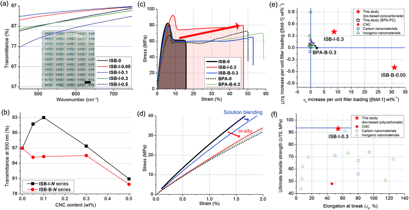 | ||
| Fig. 2 (a) Photographic image and transmission spectra of solution-cast films of the in situ prepared ISB-I-N series (scale bar: 1 cm) and (b) transmittance at 500 nm plotted against the CNC content. (c) Tensile stress–strain curves of polycarbonate and nanocomposites and (d) magnified view of the initial curves. The Ashby plot of (e) UTS vs. εb increase per unit (1 wt%) filler loading and (f) UTS vs. εb for CNC-based nanocomposites (this study) and other polycarbonate composites reported in the literature (Table S5 in the ESI†). | ||
Specimens for mechanical testing were fabricated using a mini-injection mold machine. Degradation of the molecular weight after reaching the processing temperature of 200 °C was negligible, independent of the presence of nanofillers (Table S3 in the ESI†). Uniaxial tensile measurements were conducted by fulfilling the ASTM D638-03 requirements. The tensile properties of ISB- and BPA-based PCs and their CNC nanocomposites were compared (Fig. 2c and d, and Table S4 in the ESI†). Both ISB-0 and BPA-0 exhibited an obvious yielding at 5% elongation, in common, followed by a cold drawing phenomenon, where the increase in strain largely localized on a small region of the specimen with an almost constant tensile stress. On cold drawing, a large uniaxial deformation, called brittle-to-ductile transition, was observed.60–62 This transition resulted from the local conformational change in the polymeric chains under external stress, which relieved a catastrophic crack propagation.63ISB-0 showed a lower elongation at break (εb) but a higher Young's modulus (E) and ultimate tensile strength (UTS) of 15%, 2.6 GPa, and 83 MPa, as compared to BPA-0, with respective values of 51%, 1.7 GPa, and 67 MPa.
This suggests that the ISB-based PC was glassier than the BPA-based one, and was well-matched with our previous quantum simulation results; interestingly, the alicyclic ISB imposed a stronger geometric restraint on the polymer chain than the aromatic BPA.64 Thus, the less-stretchable ISB backbone exhibited higher elastic properties compared to the BPA backbone.
The ISB-based PC was effectively strengthened by incorporating CNC nanofillers in terms of filler content. The reinforcement effectiveness of a given filler can be expressed as an increase in the UTS [or εb] per filler loading ([fold-1] wt%−1). We surveyed the literature of PC composites with CNCs and other types. The reinforcement effectiveness of this study against that of the literature is shown in Fig. 2e and f and listed in Table S5 (in the ESI†).65 In the literature, most BPA-based PC nanocomposites with carbon or clay nanomaterials exhibited insignificant changes in the UTS or εb per unit filler loading (−1 to 1, [fold-1] wt%−1). In contrast, in this study, ISB-B-0.05 achieved a 31-fold εb increase per unit filler loading. Importantly, ISB-I-0.3 showed the highest UTS of 93 MPa among all contemporary known PC and PC composites, including commercial products.10,66,67 Moreover, these records were accomplished with easy-handling of the nanofillers without complex or sophisticated approaches such as a laborious series of pretreatments for fillers.68
Morphological and rheological elucidation for mechanical differences
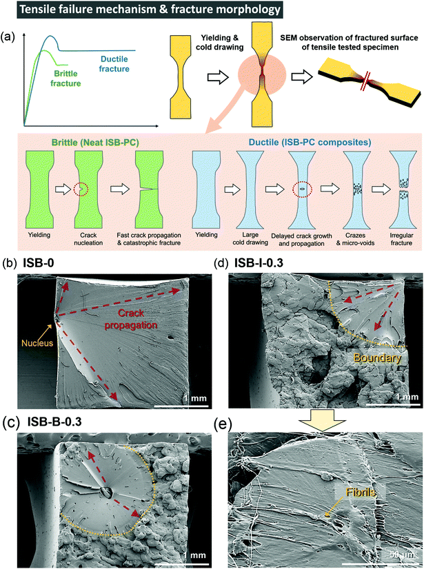
Interestingly, the ISB-based PC was significantly toughened by incorporating CNC nanofillers through both in situ and blending methods. The toughening effect is much more noticeable in the in situ method than that in the post-blending method, probably because the higher dispersibility maximizes the toughening effect of the CNCs. The E, UTS, εb, and toughness (U) values of ISB-I-0.3 were 1.9 GPa, 93 MPa, 54%, and 40 MJ m−3, respectively, which are higher than those of ISB-0. It is noteworthy that the toughness was improved 4.3-fold by CNCs through the in situ method. To understand the toughening effect of the CNCs, the failure mechanism of neat ISB-based PCs was discussed in detail (Fig. 3a). Just after an external stress is applied, a cracked nucleus is formed on the ISB-0 surface. Then, the crack rapidly propagates across the specimen. As shown in the SEM image of the failed ISB-0 specimen (Fig. 3b), the unhindered crack propagation resulted in a highly smooth fractured surface. This morphology is a typical characteristic of a brittle fracture.69The following three criteria are suggested to explain the toughening effect of CNCs. First, the introduction of CNCs increases the formation of micro-voids and crazes under loading, which promotes the ductile deformation of the specimen. As shown in the SEM image of the failed ISB-0.3 specimens (Fig. 3c–e), the fractured surface of the CNC-containing nanocomposites shows a clear boundary between the smooth and rough surfaces.70 The uneven and rough surface is direct evidence of the formation of micro-voids and crazes leading to a fabric-like structure. Therefore, the CNC nanocomposite is more extensible than the neat PC.71–73 Second, the slight decrease in E for the nanocomposites suggests that the CNC softens the polymer matrix itself, which decreases its glassy deformation. It is a well-known theory that the ion pair (i.e., sodium sulfate of the CNC surface) screens the intermolecular interactions, and its effect is more evident in a well-dispersed in situ case of decreasing E compared to that in a blended one.74 Third, the well-dispersed CNC throughout the matrix blocks the inexorable crack propagation, because the CNC bridges the interface from abruption (Fig. 3e). As an effect of CNC dispersibility, the fractured surface of ISB-I-0.3 exhibits a lower fraction of a smooth fractured surface as compared to that of ISB-B-0.3.
In contrast to those of a series of ISB-based PC nanocomposites, the reinforcement effect of the CNC is insignificant for BPA-PC, probably due to the poor interfacial interaction between the CNC and the polymer matrix, as indicated by the SEM images of the fractured surface (Fig. S6 in the ESI†). In the solubility parameter analysis, the ISB moiety is more miscible with the CNC than the BPA moiety, suggesting that the CNC fillers more strongly interact with the ISB-based polymer than with the BPA-based polymer.
The in situ CNC ISB-based PC nanocomposites showed a great advantage in impact strength compared to pristine PCs and blended nanocomposites. ISB-I-0.3 showed a 1.3-fold higher impact strength of 10.0 kJ m−2 as compared to ISB-0. This is quite encouraging because there is a concern about the fragmentation of transparent plastics into sharp pieces upon impact. However, the CNC blending method had a rather negative effect on the impact strength. ISB-B-0.3 showed a lower impact strength of 6.2 kJ m−2 compared to ISB-0 (7.6 kJ m−2). To interpret the results, the impact-fractured surface of ISB-based PCs was investigated using an SEM (Fig. 4). During the impact failure, the ISB-I-0.3 surface developed long fibrils and micro-sized cavities (Fig. S7 in the ESI†). The in situ incorporated CNC filler, which was strongly bound on the polymer chains, probably promoted the fibrillar and micro-void structure. Like a fabric, such structures contributed to the energy dissipation of the external stress. Thus, the SEM data supported the ductile behavior of ISB-I-0.3 under the impact stress. The fractured surface of ISB-0 exhibited a mackerel pattern, which resulted from the biplanar fracture by multi-level crazes; this is a characteristic phenomenon of glassy polymers.75 On the other hand, the fractured surface of ISB-B-0.3 showed several horizontal stripes, which were tear marks propagating from the notch. The tear marks suggested that the cracks propagated radially.70 These internal defects, such as CNC aggregates and voids, caused a rapid crack growth.
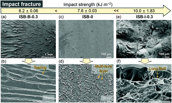 | ||
| Fig. 4 SEM images of the fractured surfaces of impact-tested specimens ((a and b) ISB-B-0.3, (c and d) ISB-0, and (e and f) ISB-I-0.3). | ||
Notably, the dispersibility of CNCs is important for the mechanical behaviors of the PC composite. This fact is further supported by the 3D X-ray micro-computed (μCT) scan and TEM data (Fig. 5). With a fixed volume cross-section of 700 μm3, the dispersibility of CNCs could be easily distinguished.76
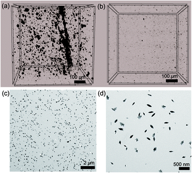 | ||
| Fig. 5 Three-dimensional X-ray μCT images of (a) ISB-B-0.3 and (b) ISB-I-0.3. (c and d) TEM images of ISB-I-0.3. | ||
The amorphous PC resin matrix is shown as a gray background, while the association of crystalline CNCs is shown as black parts. As we claimed, crystalline CNC aggregates with a size of over 1 μm were rarely found within the 700 μm3 volume cross-section of ISB-I-0.3; however, several aggregates of 1–30 μm size were filled in the ISB-B-0.3 matrix. As observed from the nano-scale investigation using a TEM, CNC fillers were well-dispersed in ISB-I-0.3, whereas it was difficult to find regularly dispersed CNCs inside ISB-B-0.3.
The viscoelastic responses of the in situ vs. solution-blended nanocomposites were investigated in the molten state using a rotational rheometer. Fig. 6a and b show the complex viscosity (η*) and storage modulus (G′), respectively. The decrease in η* and G′ for the solution-blended composites suggests that the poorly interacting CNC aggregates acted as a lubricant by inducing the molecular slip of the molten polymer chains at the interface. In the case of the in situ composites, however, both the rheological parameters increased with the CNC content, resulting from the highly entangled state between the CNC fillers and polymer chains. Therefore, the in situ-incorporated CNC fillers were hardly isolated or separated from the polymer matrix during melting but were well-dispersed even in the molten state. This reveals the presence of polymeric branches or wrapping on the CNC surface, which will be further elucidated by the model study below.
Fig. 6c presents a logarithmic plot of G′ vs. G′′ for the PC composites, the so-called Cole–Cole plot. Theoretically, a homogeneous and isotropic melt gives a linear Cole–Cole plot with a slope of 2.77,78 In general, polyethylene exhibits such a theoretical slope of 2 because the highly flexible chain gives rise to an isotropic sphere-like conformation and the low intermolecular interaction increases the rheological homogeneity. In contrast, ISB-0 has a highly rigid chain, i.e., an anisotropic rod-like conformation and a relatively high polarity, thereby affording a low slope of 0.51. The plots of the blend composites give much lower slopes compared to the control ISB-0, which indicates the deterioration of both homogeneity and isotropicity due to the poor dispersion state of anisotropic CNC particles. On the other hand, the Cole–Cole plot slopes are significantly increased in the in situ nanocomposites. ISB-I-0.3 exhibits a slope of 1.43, which is relatively closer to the theoretical value. The chemical branches of the polymeric chains on the CNCs decrease the anisotropicity, and the decreased intermolecular interaction in the presence of the CNCs leads to an increase in rheological homogeneity.
Model study of in situ chemical modification on the surface of nanocellulose
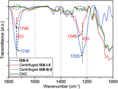
As a model study, to elucidate these unprecedented remarkable reinforcements by the in situ method, ISB-I-5 containing 5 wt% of CNCs was prepared neglecting the low molecular weights (Table S2 in the ESI†). Each homogeneous chloroform solution of ISB-I-5 and ISB-B-5 was centrifuged repeatedly 10 times to aggregate only the CNC part. It was observed through attenuated total reflectance Fourier transform infrared (ATR-FTIR) spectroscopy that a high-molecular-weight polymer portion of ISB-B-5 was easily removed by centrifugation, but the centrifuged ISB-I-5 showed many polymer fingerprints, indicating a covalent linkage with nanofillers (Fig. 7). Surely, the blue-shifted C![[double bond, length as m-dash]](https://www.rsc.org/images/entities/char_e001.gif) O and C(O)–O stretching of the centrifuged powder from pristine ISB-I-5 at 1745 and 1246 cm−1, respectively, implies the occurrence of a new carbonate source, rather than that of the ISB-based free-will polymer.79,80 This means that the carbonation of hydroxyl groups on the CNC surface occurred during in situ polymerization. The 13C cross-polarization magic-angle-spinning NMR spectrum of the centrifuged solid ISB-I-5 (modified CNCs) also supported the grafting (Fig. S8 in the ESI†). Small trace peaks of polymers were observed, where the carbonyl carbon peak was down-field-shifted from the homo-polymer and the primary methylene peak was down-field-shifted from pristine CNCs, suggesting that alcohols on the CNC surface transformed to electron-withdrawing carbonate linkages.
O and C(O)–O stretching of the centrifuged powder from pristine ISB-I-5 at 1745 and 1246 cm−1, respectively, implies the occurrence of a new carbonate source, rather than that of the ISB-based free-will polymer.79,80 This means that the carbonation of hydroxyl groups on the CNC surface occurred during in situ polymerization. The 13C cross-polarization magic-angle-spinning NMR spectrum of the centrifuged solid ISB-I-5 (modified CNCs) also supported the grafting (Fig. S8 in the ESI†). Small trace peaks of polymers were observed, where the carbonyl carbon peak was down-field-shifted from the homo-polymer and the primary methylene peak was down-field-shifted from pristine CNCs, suggesting that alcohols on the CNC surface transformed to electron-withdrawing carbonate linkages.
CNCs chemically modified with PCs are expected to show different morphologies from pure CNCs after their dispersed solution of the centrifuged powder was dried. When dimethyl sulfoxide, methanol, and 1-butanol were used as solvents, almost pure CNCs from ISB-B-5 showed well-aligned dense surfaces due to the same drying rate and regularly hydrogen-bonded structure. However, the modified CNCs from ISB-I-5 showed irregular fibrous structures due to different drying rates with the grafted polymer and partially reduced aspect ratios, as shown in Fig. 8.81 The transformation of the crystalline surface of CNCs to the amorphous polymer resulted in improved interfacial adhesion to the polymer matrix, and was realized for synergistically reinforced transparent bio-PC nanocomposites.82
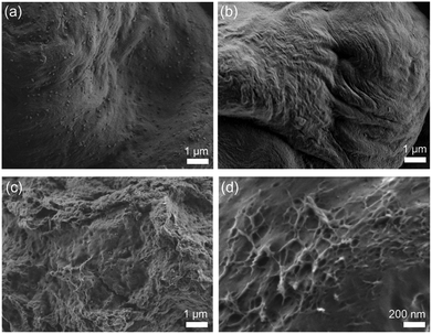 | ||
| Fig. 8 Dried solution of centrifuged ISB-B-5 (a: dimethyl sulfoxide, b: methanol) and ISB-I-5 (c: dimethyl sulfoxide, d: 1-butanol). | ||
In addition, the in vivo biocompatibility test was conducted using a rat subcutaneous model, following ISO 10993-6; the ISB-I-0.3 film achieved a lower inflammatory intensity of a “slight” level, which is an acceptable level as a body-implanted device in the guideline (Fig. S9 in the ESI†).64 These results support the potential of this bio-PC nanocomposite as hard biomedical materials such as artificial bones and dental brackets.
Conclusions
The in situ polymerized bio-PC nanocomposite by pre-dispersing CNCs in the ISB monomer unprecedentedly exhibited higher transparency and improved mechanical strength under both tensile and impact conditions, compared to neat PC and other blend controls. Good dispersion of the hydrophilic nanofiller in the ISB monomer by hydrogen bonding resulted in a highly dispersed CNC in the polymer matrix with improved tolerance to crack initiation and the resultant ductility of the nanocomposite. A 4.3-fold increased toughness of 40 MJ m−3 and a record-high UTS of 93 MPa were accomplished with 0.3 wt% content of the CNC. The in situ polymer grafting on the CNC surface strongly enhanced the interfacial interaction of the nanofiller–polymer matrix, promoting the fibrillar and micro-void structure under external stress. Consequently, the use of biomass-derived ISB as a monomer of bio-PCs not only solves the health and environmental issues caused by conventional PCs but also offers a convenient approach for fabricating robust PC nanocomposites with minimal CNC content as a bio-nanofiller. This sustainable, transparent, toughened, and biocompatible bio-EP is a promising industrial green material.Conflicts of interest
There are no conflicts of interest to declare.Acknowledgements
This work was supported by the Technology Innovation Program (10070150) funded by the Ministry of Trade, Industry & Energy (MI, Korea) and Korea Research Institute of Chemical Technology (KRICT) core project (SI1941-20, KK1941-10, and KK1941-30). S. Y. H. acknowledges support from the Basic Science Research Program through the National Research Foundation of Korea (NRF) funded by the Ministry of Science, ICT & Future Planning (2018R1C1B6002344). J. J. acknowledges support from the Korea Institute for Advancement of Technology (KIAT) through the System Industrial Base Institution Support Program (P0001939).Notes and references
- J. T. Bendler, Handbook of Polycarbonate Science and Technology, Taylor & Francis, 1999 Search PubMed.
- D. J. Brunelle, in Encyclopedia of Polymer Science and Technology, 2006, DOI:10.1002/0471440264.pst255.pub2.
- P. Morse, Chem. Eng. News, 1999, 77, 9 CrossRef.
- Editorial, Nat. Commun., 2018, 9, 2157 CrossRef PubMed.
- A. T. DiBenedetto, Mater. Sci. Eng., A, 2001, 302, 74–82 CrossRef.
- J. B. Zimmerman and P. T. Anastas, Science, 2015, 347, 1198–1199 CrossRef CAS PubMed.
- J. R. Rochester, Reprod. Toxicol., 2013, 42, 132–155 CrossRef CAS PubMed.
- S. Lee, C. Kim, H. Shin, Y. Kho and K. Choi, Chemosphere, 2019, 221, 115–123 CrossRef CAS PubMed.
- P. Sripaiboonkij, N. Sripaiboonkij, W. Phanprasit and M. S. Jaakkola, Environ. Health, 2009, 8, 36 CrossRef PubMed.
- Commercial glass filled polycarbonate database. https://www.sabic.com/en/products/specialties/lexan-resins/lexan-fr-resin/ (accessed June, 2019).
- S. Kango, S. Kalia, A. Celli, J. Njuguna, Y. Habibi and R. Kumar, Prog. Polym. Sci., 2013, 38, 1232–1261 CrossRef CAS.
- H. Xu, H. Yang, L. Zhang, Q. Ni and F. Gong, J. Appl. Polym. Sci., 2015, 132, 42262 Search PubMed.
- H. Jing, Y. Higaki, W. Ma, J. Xi, H. Jinnai, H. Otsuka and A. Takahara, Polym. J., 2014, 46, 307–312 CrossRef CAS.
- S. Y. Hwang, E. S. Yoo and S. S. Im, Polym. J., 2012, 44, 1179–1190 CrossRef CAS.
- S. Y. Hwang, W. D. Lee, J. S. Lim, K. H. Park and S. S. Im, J. Polym. Sci., Part B: Polym. Phys., 2008, 46, 1022–1035 CrossRef CAS.
- A. Dasari, Z. Z. Yu and Y. W. Mai, Polymer Nanocomposites: Towards Multi-Functionality, Springer London, 2016 Search PubMed.
- D. R. Paul and L. M. Robeson, Polymer, 2008, 49, 3187–3204 CrossRef CAS.
- K. Müller, E. Bugnicourt, M. Latorre, M. Jorda, Y. Echegoyen Sanz, J. M. Lagaron, O. Miesbauer, A. Bianchin, S. Hankin, U. Bölz, G. Pérez, M. Jesdinszki, M. Lindner, Z. Scheuerer, S. Castelló and M. Schmid, Nanomaterials, 2017, 7, 74 CrossRef PubMed.
- F. Hussain, M. Hojjati, M. Okamoto and R. E. Gorga, J. Compos. Mater., 2006, 40, 1511–1575 CrossRef CAS.
- A. K. Mohanty, S. Vivekanandhan, J.-M. Pin and M. Misra, Science, 2018, 362, 536–542 CrossRef CAS PubMed.
- M. A. S. Azizi Samir, F. Alloin and A. Dufresne, Biomacromolecules, 2005, 6, 612–626 CrossRef PubMed.
- I. Siró and D. Plackett, Cellulose, 2010, 17, 459–494 CrossRef.
- R. J. Moon, A. Martini, J. Nairn, J. Simonsen and J. Youngblood, Chem. Soc. Rev., 2011, 40, 3941–3994 RSC.
- A. Dufresne, Mater. Today, 2013, 16, 220–227 CrossRef CAS.
- H. Wei, K. Rodriguez, S. Renneckar and P. J. Vikesland, Environ. Sci.: Nano, 2014, 1, 302–316 RSC.
- A. Chakrabarty and Y. Teramoto, Polymer, 2018, 10, 517 Search PubMed.
- H. Kargarzadeh, M. Mariano, J. Huang, N. Lin, I. Ahmad, A. Dufresne and S. Thomas, Polymer, 2017, 132, 368–393 CrossRef CAS.
- H. Kargarzadeh, J. Huang, N. Lin, I. Ahmad, M. Mariano, A. Dufresne, S. Thomas and A. Gałęski, Prog. Polym. Sci., 2018, 87, 197–227 CrossRef CAS.
- M. Mariano, N. El Kissi and A. Dufresne, Eur. Polym. J., 2015, 69, 208–223 CrossRef CAS.
- A. Pei, J.-M. Malho, J. Ruokolainen, Q. Zhou and L. A. Berglund, Macromolecules, 2011, 44, 4422–4427 CrossRef CAS.
- M. Roohani, Y. Habibi, N. M. Belgacem, G. Ebrahim, A. N. Karimi and A. Dufresne, Eur. Polym. J., 2008, 44, 2489–2498 CrossRef CAS.
- T. H. Tran, H.-L. Nguyen, D. S. Hwang, J. Y. Lee, H. G. Cha, J. M. Koo, S. Y. Hwang, J. Park and D. X. Oh, Carbohydr. Polym., 2019, 205, 392–400 CrossRef CAS PubMed.
- H. T. H. Nguyen, P. Qi, M. Rostagno, A. Feteha and S. A. Miller, J. Mater. Chem. A, 2018, 6, 9298–9331 RSC.
- D. K. Schneiderman and M. A. Hillmyer, Macromolecules, 2017, 50, 3733–3749 CrossRef CAS.
- Y. Zhu, C. Romain and C. K. Williams, Nature, 2016, 540, 354–362 CrossRef CAS PubMed.
- T. Kim, J. M. Koo, M. H. Ryu, H. Jeon, S.-M. Kim, S.-A. Park, D. X. Oh, J. Park and S. Y. Hwang, Polymer, 2017, 132, 122–132 CrossRef CAS.
- W. J. Yoon, S. Y. Hwang, J. M. Koo, Y. J. Lee, S. U. Lee and S. S. Im, Macromolecules, 2013, 46, 7219–7231 CrossRef CAS.
- J. M. Koo, S. Y. Hwang, W. J. Yoon, Y. G. Lee, S. H. Kim and S. S. Im, Polym. Chem., 2015, 6, 6973–6986 RSC.
- H. R. Kricheldorf, S. Böhme, G. Schwarz and C.-L. Schultz, Macromolecules, 2004, 37, 1742–1748 CrossRef CAS.
- L. Gustini, C. Lavilla, A. M. de Ilarduya, S. Muñoz-Guerra and C. E. Koning, Biomacromolecules, 2016, 17, 3404–3416 CrossRef CAS PubMed.
- S. J. Poland and D. J. Darensbourg, Green Chem., 2017, 19, 4990–5011 RSC.
- C. Dussenne, T. Delaunay, V. Wiatz, H. Wyart, I. Suisse and M. Sauthier, Green Chem., 2017, 19, 5332–5344 RSC.
- O. Nsengiyumva and S. A. Miller, Green Chem., 2019, 21, 973–978 RSC.
- W. J. Yoon, K. S. Oh, J. M. Koo, J. R. Kim, K. J. Lee and S. S. Im, Macromolecules, 2013, 46, 2930–2940 CrossRef CAS.
- M. Zhang, W. Lai, L. Su and G. Wu, Ind. Eng. Chem. Res., 2018, 57, 4824–4831 CrossRef CAS.
- M. Zhang, W. Lai, L. Su, Y. Lin and G. Wu, Polym. Chem., 2019, 10, 3380–3389 RSC.
- S.-A. Park, J. Choi, S. Ju, J. Jegal, K. M. Lee, S. Y. Hwang, D. X. Oh and J. Park, Polymer, 2017, 116, 153–159 CrossRef CAS.
- Q. Li, W. Zhu, C. Li, G. Guan, D. Zhang, Y. Xiao and L. Zheng, J. Polym. Sci., Part A: Polym. Chem., 2013, 51, 1387–1397 CrossRef CAS.
- M. A. Rasool and I. F. J. Vankelecom, Green Chem., 2019, 21, 1054–1064 RSC.
- ASTM International, ASTM D6866-18 Method B: Standard Test Methods for Determining the Biobased content of Solid, Liquid and Gaseous Samples Using Radiocarbon Analysis. https://www.astm.org/Standards/D6866.htm.
- M. Kunioka, Appl. Microbiol. Biotechnol., 2010, 87, 491–497 CrossRef CAS PubMed.
- T. Kim, H. Jeon, J. Jegal, J. H. Kim, H. Yang, J. Park, D. X. Oh and S. Y. Hwang, RSC Adv., 2018, 8, 15389–15398 RSC.
- S. Boufi, H. Kaddami and A. Dufresne, Macromol. Mater. Eng., 2014, 299, 560–568 CrossRef CAS.
- Z.-Y. Yang, W.-J. Wang, Z.-Q. Shao, H.-D. Zhu, Y.-H. Li and F.-J. Wang, Cellulose, 2013, 20, 159–168 CrossRef CAS.
- T. Huang, K. Kuboyama, H. Fukuzumi and T. Ougizawa, Cellulose, 2018, 25, 2393–2403 CrossRef CAS.
- H. Ohkita, Y. Abe, H. Kojima, A. Tagaya and Y. Koike, Appl. Phys. Lett., 2004, 84, 3534–3536 CrossRef CAS.
- H. Ohkita, A. Tagaya and Y. Koike, Macromolecules, 2004, 37, 8342–8348 CrossRef CAS.
- A. Tagaya, H. Ohkita, M. Mukoh, R. Sakaguchi and Y. Koike, Science, 2003, 301, 812–814 CrossRef CAS PubMed.
- H. Althues, J. Henle and S. Kaskel, Chem. Soc. Rev., 2007, 36, 1454–1465 RSC.
- H. R. Brown, J. Mater. Sci., 1982, 17, 469–476 CrossRef CAS.
- C. Xiao, J. Y. Jho and A. F. Yee, Macromolecules, 1994, 27, 2761–2768 CrossRef CAS.
- Z. Zhou, A. Chudnovsky, C. P. Bosnyak and K. Sehanobish, Polym. Eng. Sci., 1995, 35, 304–309 CrossRef CAS.
- F.-C. Chang and L.-H. Chu, J. Appl. Polym. Sci., 1992, 44, 1615–1623 CrossRef CAS.
- S.-A. Park, H. Jeon, H. Kim, S.-H. Shin, S. Choy, D. S. Hwang, J. M. Koo, J. Jegal, S. Y. Hwang, J. Park and D. X. Oh, Nat. Commun., 2019, 10, 2601 CrossRef PubMed.
- J. M. Koo, H. Kim, M. Lee, S.-A. Park, H. Jeon, S.-H. Shin, S.-M. Kim, H. G. Cha, J. Jegal, B.-S. Kim, B. G. Choi, S. Y. Hwang, D. X. Oh and J. Park, Macromolecules, 2019, 52, 923–934 CrossRef.
- G. Wypych, Handbook of Polymers, Elsevier Science, 2016 Search PubMed.
- Material Properties Database. http://www.marketitfrom.com/ (accessed June, 2019).
- J. K. Muiruri, S. Liu, W. S. Teo, J. Kong and C. He, ACS Sustainable Chem. Eng., 2017, 5, 3929–3937 CrossRef CAS.
- D. Hull and T. W. Owen, J. Polym. Sci., Polym. Phys. Ed., 1973, 11, 2039–2055 CrossRef CAS.
- A. Chandra, L.-S. Turng, K. Li and H.-X. Huang, Composites, Part A, 2011, 42, 1903–1909 CrossRef.
- T. H. Tran, H.-L. Nguyen, L. T. Hao, H. Kong, J. M. Park, S.-H. Jung, H. G. Cha, J. Y. Lee, H. Kim, S. Y. Hwang, J. Park and D. X. Oh, Int. J. Biol. Macromol., 2019, 125, 660–667 CrossRef CAS PubMed.
- J.-L. Barrat, J. Baschnagel and A. Lyulin, Soft Matter, 2010, 6, 3430–3446 RSC.
- B. J. Ash, R. W. Siegel and L. S. Schadler, Macromolecules, 2004, 37, 1358–1369 CrossRef CAS.
- Q. Lu, D. X. Oh, Y. Lee, Y. Jho, D. S. Hwang and H. Zeng, Angew. Chem., Int. Ed., 2013, 52, 3944–3948 CrossRef CAS PubMed.
- E. Piorkowska, A. S. Argon and R. E. Cohen, Polymer, 1993, 34, 4435–4444 CrossRef CAS.
- K. Sakakibara, H. Yano and Y. Tsujii, ACS Appl. Mater. Interfaces, 2016, 8, 24893–24900 CrossRef CAS PubMed.
- T. Yamamoto, S. Seki, M. Hirota and M. Kamachi, Polym. J., 1987, 19, 1417–1418 CrossRef CAS.
- A. S. Lee, H. Jeon, S.-S. Choi, J. Park, S. Y. Hwang, J. Jegal, D. X. Oh, B. C. Kim and S. S. Hwang, Compos. Sci. Technol., 2017, 146, 42–48 CrossRef CAS.
- L. Mei, R. Fan, X. Li, Y. Wang, B. Han, Y. Gu, L. Zhou, Y. Zheng, A. Tong and G. Guo, Polym. Chem., 2017, 8, 1664–1671 RSC.
- J. Y. Kim, C. S. Ha and N. J. Jo, Polym. Int., 2002, 51, 1123–1128 CrossRef CAS.
- Q. Xu, J. Yi, X. Zhang and H. Zhang, Eur. Polym. J., 2008, 44, 2830–2837 CrossRef CAS.
- W. Xia, X. Qin, Y. Zhang, R. Sinko and S. Keten, Macromolecules, 2018, 51, 10304–10311 CrossRef CAS.
Footnotes |
| † Electronic supplementary information (ESI) available: Experimental section and complete characterization data. See DOI: 10.1039/c9gc02253h |
| ‡ These authors contributed equally. |
| This journal is © The Royal Society of Chemistry 2019 |

