 Open Access Article
Creative Commons Attribution 3.0 Unported Licence
Transport of hyperpolarized samples in dissolution-DNP experiments
Alexey S.
Kiryutin
ab,
Bogdan A.
Rodin
ab,
Alexandra V.
Yurkovskaya
 ab,
Konstantin L.
Ivanov
 *ab,
Dennis
Kurzbach
 *c,
Sami
Jannin
d,
David
Guarin
e,
Daniel
Abergel
e and
Geoffrey
Bodenhausen
 *e
*e
aInternational Tomography Center SB RAS, Institutskaya 3A, Novosibirsk, 630090, Russia. E-mail: ivanov@tomo.nsc.ru
bNovosibirsk State University, Pirogova 2, Novosibirsk, 630090, Russia
cUniversity Vienna, Faculty of Chemistry, Institute of Biological Chemistry, Währinger Straße 38, 1090 Vienna, Austria. E-mail: dennis.kurzbach@univie.ac.at
dUniversité de Lyon, Centre de RMN à Très Hauts Champs (FRE2034 CNRS/UCBL/ENS Lyon), 5 rue de la Doua, 69100 Villeurbanne, France
eLaboratoire des biomolécules, LBM, Département de chimie, École normale supérieure, PSL University, Sorbonne Université, CNRS, 75005 Paris, France. E-mail: geoffrey.bodenhausen@ens.fr
First published on 7th June 2019
Abstract
Dissolution dynamic nuclear polarization (D-DNP) experiments rely on the transfer of a sample between two high-field magnets. During this transfer, samples might experience passage through regions where the stray fields of the magnets are very weak, can approach zero, and even change their sign. This can lead to unexpected spectral features in spin systems that undergo transitions from weak- to strong-coupling regimes and vice versa, much like in field cycling nuclear magnetic resonance experiments. We herein demonstrate that the spectral features observed in D-DNP experiments can be rationalized, provided the time-dependence of the spin Hamiltonian upon field cycling is sufficiently adiabatic. Under such conditions, a passage through a weak static field can lead to the emergence of a long-lived state (LLS) based on an imbalance between the populations of singlet and triplet states in pairs of nuclei that are strongly coupled during the passage through low field. The LLS entails the appearance of anti-phase multiplet components upon transfer to a high-field magnet for observation of NMR signals.
I. Introduction
Dissolution dynamic nuclear polarization (D-DNP) is a method to enhance signal amplitudes in solution-state nuclear magnetic resonance (NMR) experiments.1 Spectacular signal enhancements above four orders of magnitude2 can be attained, rendering novel applications possible in fields ranging from the monitoring of chemical reactions,3,4 metabolomics,5,6 studies of interactions7 or real-time biomolecular NMR.8 The D-DNP method is based on spin hyperpolarization of a sample at temperatures close to 1 K by employing slightly off-resonance microwave saturation of the Electron Paramagnetic Resonance (EPR) spectra of paramagnetic polarization agents, such as stable paramagnetic molecules,9–11 radical mixtures,12 UV-induced radical centers13 or paramagnetic microporous matrices.14 Once hyperpolarization has been achieved, i.e. once most nuclear spins have been aligned parallel to (or against) the direction of the static magnetic field, the sample can be rapidly dissolved by a burst of heated solvent and the solution is subsequently propelled towards an NMR spectrometer for detection. Alternatively, the sample can be shuttled to the NMR spectrometer as a solid pellet and dissolved near or in the spectrometer.15 In both cases, regardless whether one transfers a solid or a liquid, it is advantageous to maintain a non-vanishing “guiding” magnetic field during the transfer to prevent losses of polarization during the transfer.Typically, when combining D-DNP with the transfer of a liquid sample, both the polarization field and the detection field are strong (on the order of several Tesla), but during the transport between the two strong fields the sample passes through a region of a weak magnetic field, in the milli-Tesla range. This can lead to substantial losses of polarization because (i) relaxation times are often shorter at low fields and (ii) the spins can lose their orientation when passing through a close-to-zero-field zone. The magnetic field might even change its direction when the magnets are actively compensated (“ultra-shielded”) by coils of opposite polarity to the main coils, so that the sample may be exposed to a vanishing field during their ejection or injection. One should keep in mind that spins may be depolarized when the variation of the field is non-adiabatic, i.e. when the spins do not follow the field's direction.16 To overcome such problems, the sample can be transported through a “magnetic tunnel” that bridges the gap between the DNP and NMR magnets.17 Experiments clearly demonstrated that such a tunnel with an internal magnetic field Btrans of approximately 0.9 T dramatically increases the performance of D-DNP experiments, particularly for hyperpolarized protons. Indeed, the signal enhancement ε can be increased by a factor of 2 < ε < 20 compared to experiments performed without magnetic tunnel.17 In addition, it was noted in some cases that the use of a magnetic tunnel to sustain Btrans during the transfer may lead to a change of the appearance of the multiplets after D-DNP. Specifically, in systems with two or more coupled spins, the multiplet components may change in sign when comparing experiments with Btrans > 0.9 T and with Btrans < 1 mT. Such effects were more pronounced for weakly coupled spin pairs, i.e. the results obtained with and without magnetic tunnel can be dramatically different, whereas, for strongly coupled spin pairs, varying Btrans does not significantly affect the appearance of the NMR lines. As usual, the notion of a “weakly coupled spin pair” stands for two interacting spins with a coupling strength J that is much smaller than the difference δν between their chemical shifts due to the Zeeman interactions with the external magnetic field; otherwise, the spins are considered to be “strongly coupled”.
In earlier work,17 the above-mentioned effects have not been explained since attention was focused on the total signal enhancement. Here we provide an explanation for the dependence of the appearance of the detected multiplets on Btrans. We argue that these effects can be traced back to proton polarizations in coupled two-spin systems that can reach almost P(1H) = 100%,18 resulting in the formation of a ‘population imbalance’19 between the triplet and singlet states, known as Triplet–Singlet Imbalance (TSI) after rapid transfer to solution state conditions. Generally, the amplitudes of the components of the multiplets reflect the polarization. In principle, this allows one to determine the absolute spin polarization by spin polarimetry magnetic resonance.18 It is well documented20–22 that a TSI can constitute a long-lived state (LLS), i.e. it can have a lifetime TLLS that is longer than the relaxation time T1 of the individual participating spins. To fulfill the inequality TLLS > T1, it is required that (i) the spins are strongly coupled and (ii) intra-pair dipolar couplings constitute the dominant relaxation mechanism. Similar effects are expected for relaxation driven by other mechanisms when the spins experience fluctuating local fields that are correlated with each other.23,24 Indeed, dipolar relaxation within a two-spin system cannot drive singlet–triplet transitions, which can only be induced by other mechanisms such as dipolar couplings to a third spin or anisotropic chemical shifts. However, these mechanisms are often less efficient and therefore do not significantly curtail the lifetime of the TSI. For protons, the TLLS/T1 ratio25 can be as high as 45 and TLLS can be as long as 4 minutes;26–28 for nuclei such as 13C or 15N in suitably designed molecules, extremely long TLLS values can be achieved, reaching 1 hour.21,29,30 Although the TSI lifetime is reduced by the presence of paramagnetic agents (significant radical concentrations are common in D-DNP experiments) TLLS can still be longer than T1, since the local fields due to paramagnetic agents experienced by the two spins are partly correlated.24,31
Here we argue that for a weakly coupled two-spin system that passes through a low-field area during sample transport, where the spins enter a strong coupling regime (meaning 2JHH > δν), the longitudinal Zeeman spin polarization relaxes efficiently whereas the TSI persists. In other words, if the condition T1 < ttrans < TLLS is fulfilled (ttrans being the time the spins spend in the field Btrans), the multiplets feature patterns with positive and negative contributions that result from a TSI being transferred from low- to high-field conditions. By using a magnetic tunnel and maintaining a magnetic field Btrans ≈ 0.9 T during ttrans one can avoid low-field passages. Hence the resulting multiplets have the usual in-phase appearance, reflecting the net polarization. In this respect, it is important to note that the decay of net polarization is enhanced by passages through regions with very low or vanishing fields, whereas a TSI is sustained most efficiently in the absence of a field and is therefore likely to survive passages through low-field regions. This effect is exacerbated if the inequality TLLS > T1 holds.
To validate these arguments, we present D-DNP experiments obtained with Btrans ≈ 0.9 T and Btrans < 1 mT, combined with measurements of T1 and TLLS relaxation times for weakly and strongly coupled proton spin pairs. We demonstrate that in all cases,17 the presence or absence of a long-lived TSI explains the appearance of the multiplets in D-DNP experiments. We anticipate that these results may be useful for maximizing signal enhancements and for sustaining spin hyperpolarization.
II. Methods
A. Sample preparation
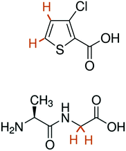
The structures of the compounds under investigation are shown in Scheme 1. For sample 1, 25 μL of a solution containing 50 mM TEMPOL and 2 M 3-chlorothiophene-2-carboxylate (CTC) in phosphate buffer saline (PBS) at pH 10 was mixed 1![[thin space (1/6-em)]](https://www.rsc.org/images/entities/char_2009.gif) :
:![[thin space (1/6-em)]](https://www.rsc.org/images/entities/char_2009.gif) 1 v/v with glycerol-d8, yielding 50 μL. For sample 2, 25 μL of a solution containing 50 mM TEMPOL and 1 M Ala-Gly in ethanol-d6/D2O (50/50 v/v) at pH 7.4 were mixed 1
1 v/v with glycerol-d8, yielding 50 μL. For sample 2, 25 μL of a solution containing 50 mM TEMPOL and 1 M Ala-Gly in ethanol-d6/D2O (50/50 v/v) at pH 7.4 were mixed 1![[thin space (1/6-em)]](https://www.rsc.org/images/entities/char_2009.gif) :
:![[thin space (1/6-em)]](https://www.rsc.org/images/entities/char_2009.gif) 1 v/v with glycerol-d8. In the dissolution step, both samples 1 and 2 were diluted 100-fold by D2O. The relaxometry measurements were carried out in thermal equilibrium without D-DNP with the following concentrations: 30 mM CTC, 30 mM Ala-Gly, 20 mM ethylenediaminetetraacetic acid (EDTA) in D2O at pH 12.3 (sample 3), 30 mM CTC, 30 mM Ala-Gly, 20 mM EDTA, 0.5 mM TEMPOL in D2O at pH 12.3 (sample 4). Dissolved oxygen was removed from samples 3 and 4 by bubbling with nitrogen gas for 15 minutes. To allow direct comparison with D-DNP experiments, the concentration of TEMPOL in sample 4 was the same as in samples 1 and 2 after 100-fold dilution.
1 v/v with glycerol-d8. In the dissolution step, both samples 1 and 2 were diluted 100-fold by D2O. The relaxometry measurements were carried out in thermal equilibrium without D-DNP with the following concentrations: 30 mM CTC, 30 mM Ala-Gly, 20 mM ethylenediaminetetraacetic acid (EDTA) in D2O at pH 12.3 (sample 3), 30 mM CTC, 30 mM Ala-Gly, 20 mM EDTA, 0.5 mM TEMPOL in D2O at pH 12.3 (sample 4). Dissolved oxygen was removed from samples 3 and 4 by bubbling with nitrogen gas for 15 minutes. To allow direct comparison with D-DNP experiments, the concentration of TEMPOL in sample 4 was the same as in samples 1 and 2 after 100-fold dilution.
B. D-DNP experiments
All D-DNP experiments were performed by vitrifying 50 μL of samples 1 and 2 (see above) in liquid helium. Hyperpolarization was achieved by microwave irradiation at either 187.90 GHz (positive DNP) or 188.38 GHz (negative DNP) in a magnetic field BDNP = 6.7 T at a temperature TDNP = 1.2 K. The microwave frequency was modulated at 1 kHz with a saw-tooth function over a bandwidth of 100 MHz. After steady-state hyperpolarization was reached, the samples were dissolved and propelled out of the DNP apparatus by a burst of 5 mL of superheated D2O (under 1.05 MPa pressure and at a temperature of 453 K). Subsequently, the hyperpolarized solutions were transferred by pressurized helium gas (∼0.7 MPa) to the NMR spectrometer for detection. Three different transfer conditions were probed. (i) Transfer through a magnetic tunnel at Btrans ≈ 0.9 T for ttrans = 4 s before injection into an NMR tube waiting in the spectrometer, (ii) transfer through the ambient low field Btrans < 1 mT for ttrans = 4 s (without passing through of a magnetic tunnel) prior to injection, and (iii) transfer through ambient field during 4 s plus an additional interval tdelay = 10 s before injection such that the total transfer time amounted to ttrans = 14 s, during which the sample was kept in low field Btrans < 1 mT. Detection after injection was achieved by a train of hard 5° pulses after a delay of ca. 3 s to allow turbulences to settle. All experiments were performed on a Bruker HD II NMR spectrometer operating at B0 = 9.4 T (400 MHz) equipped with a 10 mm BBO probe set to a temperature of 298 K (sample 1) or on a Bruker HD III NMR spectrometer operating at B0 = 11.7 T (500 MHz) equipped with a 5 mm TXI cryo-probe probe set to a temperature of 298 K (sample 2).All data were processed using home-written scripts in MATLAB. All free induction decays (FIDs) were apodized by a Gaussian window function prior to Fourier transformation and baseline correction.
C. T 1-measurements at variable field
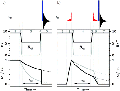
T 1 relaxation times were measured at a high field of 9.4 T using the standard inversion-recovery protocol. We also performed T1-measurements at variable fields as described before.26 All relaxation experiments were done using a 400 MHz NMR spectrometer with a magnetic field B0 of 9.4 T. This spectrometer is equipped with a field-cycling device, which allows one to switch the field from B0 to any field in the range 10 nT < Brel < 9.4 T in less than 0.4 s. To switch the field, we mechanically move the sample as described in ref. 32. A schematic protocol for measuring relaxation times T1 at variable fields is shown in Fig. 1a. Here the equilibrium polarization is recovered at B = B0 in step 1, in step 2 the field is switched B0 → Brel, in step 3 longitudinal spin relaxation takes place at the field Brel, and after switching Brel → B0 (step 4) the NMR signal is measured at B = B0 in step 5: a non-selective 90° pulse is applied and the FID is detected. As usual, the NMR spectrum is obtained by Fourier transform of the FID.D. LLS measurements at high field
To generate and observe the LLS of interest, we used the adiabatic-passage spin order conversion (APSOC) method,33,34 where singlet order is generated from the longitudinal thermal spin magnetization by an adiabatically ramped RF-field. To preserve the TSI, a strong RF spin-locking field is used; to convert the singlet order into observable magnetization the RF-field is ramped down adiabatically. Finally, a non-selective 90° pulse is applied, and the FID signal is acquired. By varying the duration τSL of the spin-locking field, we can determine TLLS by fitting to an exponential decay. The choice of the frequency and peak amplitude of the RF-field and of the optimum switching times were discussed in detail in previous publications.33–35E. LLS measurements at variable field
We combined the APSOC method with experiments at variable fields (see Fig. 1b). In a first step (1), the thermal polarization is allowed to recover in a suitable interval, usually ca. 3T1. Immediately after generating the singlet order by an adiabatically ramped RF-field (2), we performed a fast field jump from B0 to the relaxation field Brel (3), where we let the spins relax during the time τrel (4). After that, we performed a field jump Brel → B0 (5), applied an adiabatically decreasing RF-field (6) and detected the NMR signal (7). The signal decay as a function of τrel allowed us to determine TLLS or T1 for each field Brel. The same method has been used in our earlier work26 on field-cycling relaxometry of singlet order. It is worth noting that the adiabatically ramped RF-field was optimized separately for the pairs of protons in CTC and in Ala-Gly to have high yields of the singlet order in each case.III. Results
A. D-DNP experiments
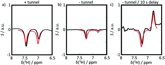
Six experiments were performed for sample 1 containing CTC. The experiments employed either positive or negative DNP. After dissolution, the samples were transferred to the detection spectrometer either (i) through a magnetic tunnel maintaining a constant magnetic field Btrans = 0.9 T, or (ii) without magnetic tunnel through the ambient magnetic field, which was determined to vary between 0.5 < Btrans < 1.5 mT, or (iii) without magnetic tunnel through the same ambient magnetic field, followed by storage in the ambient magnetic field for a delay tdelay = 10 s, prior to injection into the NMR system.From the viewpoint of spin dynamics, these experiments show the following behavior of the two protons of CTC (cf.Scheme 1): (i) the magnetic tunnel avoids passages through low-field regimes and provides a continuous quantization field (“guiding” field) for the spins that remain weakly coupled, (ii) without the magnetic tunnel the spins pass through a low-field range where the TSI constitutes an LLS, and (iii) in an additional storage time tdelay = 10 s at low field, most of the longitudinal Zeeman spin polarization dissipates through T1-relaxation, so that only the long-lived TSI remains. The invariance of this triplet–singlet imbalance under arbitrary rotations renders it immune to relaxation in the absence of a quantization field.
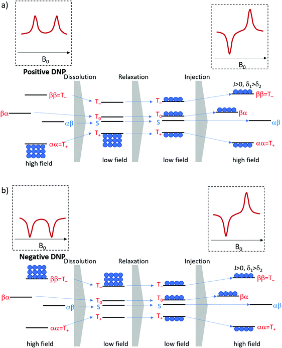
The expected behavior of the hyperpolarized spin order is shown in Fig. 2. The NMR spectrum of CTC comprises two poorly resolved doublets. Depending on the expectation values 〈I1z〉 and 〈I2z〉 of the longitudinal Zeeman polarizations of the two spins, the two doublets can have the same or opposite phases. Here we consider the two cases of positive and negative DNP, corresponding to overpopulated T+ and T− states of a spin pair, respectively. As a result of the passage through low fields, the populations are redistributed equally among the three triplet states, whereas the TSI remains unchanged. Hereafter, the TSI is defined as pTSI = 〈pT〉 − pS where the average triplet population is  . Subsequent adiabatic transport to the NMR detection field gives rise to a depleted |αβ〉 state and consequently to an (Î1z − Î2z) spin order, which is independent of the sign of the hyperpolarization. If the sign of either J or (δ1 − δ2) is changed, it is the |βα〉 state that will be depleted, giving rise to a sign inversion of the polarizations of both spins (as usual, by α and β we denote states with the z-projections
  and
and  , respectively). Hence, the expectation values of the Zeeman spin polarizations are opposite, i.e. 〈I1z〉 = −〈I2z〉. The spin order is thus described by a term (Î1z − Î2z) in the spin density operator that does not depend on the sign of DNP, but depends only on the TSI, which is positive in the present case.
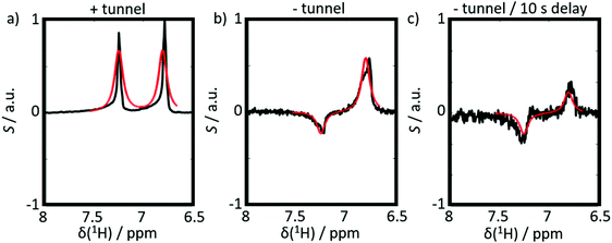
The results of six complementary DNP experiments performed for CTC are shown in Fig. 3 and 4. Obviously, case (i), where Btrans = 0.9 T, leads to longitudinal Zeeman polarization, with an all positive or all negative multiplet, i.e. (Î1z + Î2z) spin order is detected, the sign of which depends on the sign of the DNP (cf.Fig. 3a and 4a). Additionally, a slight asymmetry is observed, presumably due to the presence of a weakly populated TSI that survives the transfer through the tunnel. In contrast, in case (ii), where Btrans < 1 mT, one observes – in accordance with the expectations outlined in Fig. 2 – a negative low-field (left-hand) component of the multiplet and a positive high-field (right-hand) component of the multiplet, i.e. the (Î1z − Î2z) spin order is generated. (Note that due to radiation damping as a consequence of large water polarizations, the multiplets are not fully resolved.) This observation holds for both cases of positive and negative DNP (cf.Fig. 3b and 4b), i.e. the (Î1z − Î2z) spin order does not change its sign depending on the sign of DNP. Note that in case (ii) the TSI leads to signals where the two doublet components have opposite phases with respect to each other. For pure (Î1z − Î2z) spin order, one should observe |〈I1z〉| − |〈I2z〉| = 0. However, the observed patterns are accompanied by weakly populated longitudinal order of the spin pair, (Î1z + Î2z), as evidenced by the fact that |〈I1z〉| − |〈I2z〉| ≠ 0. In other words, longitudinal Zeeman order does not entirely vanish during dissolution and transfer of the sample. In case (iii) however, with an additional storage time tdelay = 10 s at low field, the longitudinal spin polarization has almost completely relaxed prior to detection and only TSI-derived polarization is observed due to the longer life-times of the latter in the absence of a field. As a result, one observes |〈I1z〉| − |〈I2z〉| ≈ 0 (cf.Fig. 3c and 4c).
When changing the microwave irradiation frequency to switch from positive to negative DNP, one observes that the sign of the longitudinal Zeeman magnetization changes in all three cases, but not the sign of the TSI (in accordance with Fig. 2). Hence, the polarization (Î1z + Î2z) changes its sign, while the TSI-associated opposite contributions to the polarization (Î1z − Î2z) do not. A comparison of experiments with positive and negative DNP thus allows one to probe the role of long-lived TSI in the hyperpolarization process. Note that negative DNP leads to superior 1H polarization, which results in a better signal-to-noise ratio in Fig. 4a–c as compared to Fig. 3a–c. However, it should be noted that the loss of (Î1z + Î2z) order during the heating and dissolution process of the samples also depends critically on the speed of the manual operation of our D-DNP setup, which introduces a source of uncertainty. This might, e.g. explain that the (Î1z + Î2z) contribution to the observed signals in Fig. 3b (positive DNP) is smaller than in Fig. 4b (negative DNP).
To compare our results to a case where the protons are strongly coupled even at high field, we investigated the dipeptide Ala-Gly, focusing on the strongly coupled geminal Hα protons of the Gly residue.
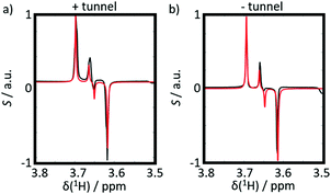
We analyzed two experiments, both with negative DNP, with and without magnetic tunnel, i.e. either with a transfer through a constant field Btrans = 0.9 T, or through the ambient magnetic field Btrans = 1 mT. The results are shown in Fig. 5. As expected, in contrast to CTC, both experiments on Ala-Gly show the same results, since the TSI behaves qualitatively in the same way in fields Btrans = 0.9 T or 1 mT. The doublets show nearly pure (Î1z − Î2z) spin order almost without any evidence of any (Î1z + Î2z) order. The up-down patterns reflect the fact that the J-coupling between the geminal Hα protons in Gly is negative.
B. Relaxation measurements
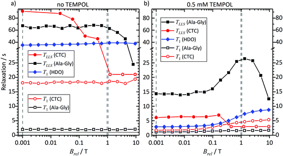
To rationalize the observations in Fig. 3 to 5, we investigated the field dependence of the relaxation times and rates, known as Nuclear Magnetic Relaxation Dispersion (NMRD) curves, of samples 3 and 4, i.e. of solutions of CTC and Ala-Gly, with and without TEMPOL, at thermal equilibrium (without DNP). The results are shown in Fig. 6 and 7, respectively, for fields in the range 1 mT < Brel < 9.4 T.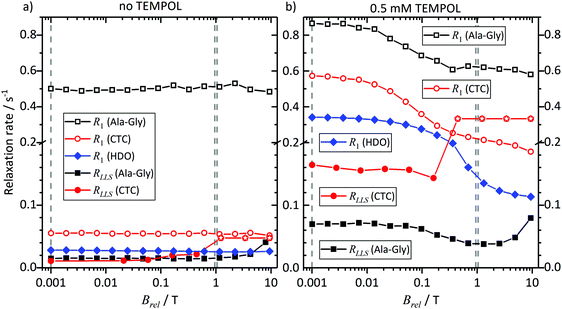 | ||
| Fig. 7 The same experimental data as in Fig. 6, but shown for relaxation rates RLLS = 1/TLLS and R1 = 1/T1 instead of relaxation times TLLS and T1. To discriminate between low and high relaxation rates we used two different scales along the vertical axes of the plots. | ||
CTC features two weakly coupled aromatic protons at high magnetic fields. However, as the Brel field decreases, the two spins pass through the strong coupling regime. The TSI has a lifetime that increases with diminishing field, while T1 decreases.36 At Brel ≈ 0.3 T the two relaxation times become similar, since the curves in Fig. 6 and 7 cross. At fields Brel < 0.3 T the TSI lifetimes become significantly longer than T1. Thus, TLLS ≈ 3.5T1 in the Earth's magnetic field. In other words, the TSI constitutes a long-lived state. This is observed despite the presence of 0.5 mM TEMPOL.
In contrast, the two geminal Gly Hα protons in Ala-Gly show a different behavior. They form a strongly coupled spin pair over the entire accessible field range. Furthermore, TLLS ≫ T1 holds independently of the experimental conditions, even in the presence of 0.5 mM TEMPOL.
Hence, we can conclude: the TSI is the longest-lived population distribution, provided that the spin system evolves in a magnetic field Brel ≤ 1 mT. In both systems under study, an LLS appears at low fields, and remains long-lived even in the presence of 0.5 mM TEMPOL as after dissolution and transfer in the D-DNP experiments.
Comparing the lifetimes with 0.5 mM TEMPOL during sample transfer through a magnetic tunnel that maintains Btrans = 0.9 T, one finds that TLLS = 6 s for CTC and 25 s for Ala-Gly. It is worth mentioning that TLLS of Ala-Gly is the longest observed time constant in our experiments (even longer than T1 of the proton in HDO). In the case of Gly, TLLS is significantly longer than T1 at all fields, which explains why experiments with and without magnetic tunnel yield comparable results.
Note that the effect of TEMPOL at concentrations used in the D-DNP experiments on the TLLS relaxation times is much weaker for the Hα protons of Glycine in Ala-Gly than for the proton pair in CTC. Comparing the TSI lifetimes in the two systems at magnetic fields Brel ≤ 1 mT, one finds a long TLLS = 90 s for CTC in the absence of TEMPOL, but a short TLLS = 68 s for Ala-Gly. In the presence of 0.5 mM TEMPOL on the other hand, TLLS drops to 6 s for CTC, but only to 15 s for Ala-Gly.
IV. Discussion
A semi-quantitative explanation for the observed spectra can be proposed when considering that the polarizations undergo adiabatic transitions between low- and high-field regimes. Under these conditions, the explanation for the unusual polarization patterns in the D-DNP experiments is as follows: when the hyperpolarized spin system is kept at a low magnetic field, relaxation within the triplet manifold is efficient, yet the relaxation of the TSI itself is not. Hence, the three triplet states can be assumed to be in thermal equilibrium with respect to each other prior to detection, but the average of their populations 〈pT〉 will exceed the population of the singlet state, i.e. the triplet states are overpopulated so that 〈pT〉 > pS and the TSI value is positive, pTSI = 〈pT〉 − pS > 0. The energies of the states at low fields are shown in Scheme 1. The scheme assumes that the difference in the Larmor frequencies, δν, of the two spins is smaller than their mutual coupling J. At the same time, we assume that the average NMR Larmor frequency at this field, ν0, is still much greater than J – a common assumption even in fields as low as the Earth's field, which only breaks down if the sample is immersed in ultralow fields below 1 μT.37–39 The frequency ν0 in a magnetic field of a strength B0 is equal to | (1) |
| δν = (δ1 − δ2)ν0 | (2) |
When the sample is adiabatically transported to high fields, the populations smoothly follow the evolution of the eigenstates. Hence, since the T± states are eigenstates of the Hamiltonian at any field, their populations after adiabatic transport remain identical to their low-field ones. For the two central states, we conclude that the highest of these two states acquires the population of the T0 state and becomes overpopulated, while the lowest state becomes depleted. The two eigenstates of interest are the αβ and βα states in high field. Their energies are
 | (3) |
For clarity, we assume that δ1 > δ2. Consequently, the αβ level has a lower energy than the βα state and becomes depleted. In this situation, the polarization of spin 1 is negative and polarization of spin 2 is positive. The expectation values of the z-magnetizations of spins are
 | (4) |
If the sign of J is negative, the signs are reversed.
Hence, after relaxation of Zeeman polarization, but persistence of the TSI at low fields, one should expect that the sample transport to high field would lead to a negative polarization of spin 1 (the one with the larger chemical shift, larger shielding constant, resonating on the high-field side) and positive polarization of spin 2. Hence, the difference in polarizations
| δI = 〈I1z〉 − 〈I2z〉 | (5) |
To further confirm our reasoning, we simulated the expected spectra. To this end, we followed the strategy outlined in ref. 43. We started from a density matrix at low field that describes the polarization of a two-spin system before an adiabatic transfer to a higher field in the NMR spectrometer used for detection. We consider two possible low fields B ≈ 0 and B = Btrans. The initial density matrix comprises contributions with different weights of longitudinal Zeeman polarization, (Î1z + Î2z), and of the TSI, (Î1·Î2). Subsequently, one can express the density matrix in the basis of the eigenstates at low field:
|1〉 = |T+〉, |2〉 = cos![[thin space (1/6-em)]](https://www.rsc.org/images/entities/char_2009.gif) θ|αβ〉 + sin θ|αβ〉 + sin![[thin space (1/6-em)]](https://www.rsc.org/images/entities/char_2009.gif) θ|βα〉, |3〉 = −sin θ|βα〉, |3〉 = −sin![[thin space (1/6-em)]](https://www.rsc.org/images/entities/char_2009.gif) θ|αβ〉 + cos θ|αβ〉 + cos![[thin space (1/6-em)]](https://www.rsc.org/images/entities/char_2009.gif) θ|βα〉, |4〉 = |T−〉 θ|βα〉, |4〉 = |T−〉 | (6) |
The angle  will decrease during the transition from strong to weak coupling, i.e. when increasing the magnetic field. In the next step, we set all coherences to zero, i.e. drop all off-diagonal elements, and treat only the populations of eigenstates. In the last step, we evaluate the populations of high-field states by performing an adiabatic correlation of low-field and high-field states and calculate the resulting NMR spectrum as described previously.44 Hence, we do not consider explicitly the time dependence of the magnetic field during sample transport. The reason is that the B(t) dependence is not known precisely in the present case and that the two-spin systems under consideration are very simple: in such systems there are no level crossings (or anti-crossings) at intermediate magnetic fields. Generally, level anti-crossings are known45,46 to affect the redistribution of polarization in dependence of (among other factors) the speed of passage through anti-crossings; however, in the present case a simpler theoretical consideration is sufficient to explain the experimental observations.
The resulting theoretical spectra (red lines) are superimposed onto the experimental spectra (black lines) in Fig. 3–5. Indeed, we find that the calculated spectra match the experimental observations under the assumptions discussed above. In brief, if the initial spin order is given predominantly by TSI, we observe signals with positive and negative contributions. On the other hand, if we start from the longitudinal Zeeman polarization, (Î1z + Î2z), we observe only positive signals. We assumed that the J-coupling between the neighboring aromatic protons in CTC is positive, while the germinal J-coupling between the Hα protons in Gly is negative. This leads to a change of the sign of the (Î1z − Î2z) spin order. All observed spectra could be modelled with these simple assumptions, thus corroborating our argumentation.
Together with the relaxation study, these considerations provide an explanation of the multiplet patterns in the D-DNP experiments. In experiments on CTC without any magnetic tunnel, the longitudinal spin order decays, while the TSI remains, giving rise to (Î1z − Î2z) spin order after adiabatic sample transfer to the NMR detection field. In experiments on CTC with a magnetic tunnel, the opposite is observed: the TSI disappears rapidly as the spins are weakly coupled during the transfer at B = Btrans, while the longitudinal Zeeman order survives as the tunnel provides enough field intensity. In Ala-Gly, the TSI is long-lived at both B ≈ 0 and B = Btrans so that the detected spin order is predominantly due to the TSI.
V. Conclusions
In conclusion, we present a rationale for the appearance of unusual multiplet patterns of spectra in D-DNP experiments that depend on the magnetic field during the transfer of the samples from the DNP polarizer to the detection NMR spectrometer. The understanding of the adiabatic transfer between high- and low-field conditions allows one to rationalize NMR data in various D-DNP applications and is a prerequisite for a quantitative analysis of signal intensities.Indeed, an adiabatic transfer of magnetization from low to high field for NMR detection can explain the observed multiplet patterns. In systems that comprise two spins that pass through a strong coupling regime during the transfer, (Î1z − Î2z) contributions are dominant after transfer to high field. This stems from a long-lived TSI that forms during the low-field passage. In contrast, in systems that do not pass through a strong coupling regime during the transfer, the detected signals can be described by pure (Î1z + Î2z) spin order magnetization. We anticipate that in higher spin systems a more advanced theoretical treatment would be necessary, which would take into account the precise time dependence of the magnetic field during sample transfer and the presence of level anti-crossings. However, for simple two-spin systems, like the ones studied here, a semi-qualitative consideration of the sample transfer process is sufficient.
Our study clearly shows that high polarization levels achieved in D-DNP experiments provide not only strong Zeeman polarization but also a significant TSI after dissolution and transfer. Depending on the conditions of the transfer from the polarizer to the NMR detection field, the TSI may be the dominant origin of the resulting spectra. The long-lived character of the TSI can be used to preserve non-equilibrium spin order, which is an important source of NMR signal enhancement.
Conflicts of interest
There are no conflicts to declare.Acknowledgements
The project has received funding from the European Research Council (ERC) under the European Union's Horizon 2020 research and innovation programme (“Dilute para-water”, grant agreement no. 339754 and “HP4all”, no. 714519). The authors acknowledge Bruker BioSpin for providing the D-DNP equipment. We acknowledge the Russian Ministry of Science and Higher Education for providing access to NMR facilities at ITC SB RAS and the Russian Science Foundation (project 19-43-04116).References
- J. H. Ardenkjaer-Larsen, B. Fridlund, A. Gram, G. Hansson, L. Hansson, M. H. Lerche, R. Servin, M. Thaning and K. Golman, Proc. Natl. Acad. Sci. U. S. A., 2003, 100, 10158–10163 CrossRef CAS PubMed.
- L. Lumata, A. K. Jindal, M. E. Merritt, C. R. Malloy, A. D. Sherry and Z. Kovacs, J. Am. Chem. Soc., 2011, 133, 8673–8680 CrossRef CAS PubMed.
- A. Sadet, E. M. M. Weber, A. Jhajharia, D. Kurzbach, G. Bodenhausen, E. Miclet and D. Abergel, Chem. – Eur. J., 2018, 24, 5456–5461 CrossRef CAS PubMed.
- H. Zeng, Y. Lee and C. Hilty, Anal. Chem., 2010, 82, 8897–8902 CrossRef CAS PubMed.
- J. N. Dumez, J. Milani, B. Vuichoud, A. Bornet, J. Lalande-Martin, I. Tea, M. Yon, M. Maucourt, C. Deborde, A. Moing, L. Frydman, G. Bodenhausen, S. Jannin and P. Giraudeau, Analyst, 2015, 140, 5860–5863 RSC.
- M. Liu and C. Hilty, Anal. Chem., 2018, 90, 1217–1222 CrossRef CAS PubMed.
- D. Kurzbach, E. Canet, A. G. Flamm, A. Jhajharia, E. M. Weber, R. Konrat and G. Bodenhausen, Angew. Chem., Int. Ed., 2017, 56, 389–392 CrossRef CAS PubMed.
- P. R. Jensen, M. Karlsson, M. H. Lerche and S. Meier, Chem. – Eur. J., 2013, 19, 13288–13293 CrossRef CAS PubMed.
- C. Sauvee, G. Casano, S. Abel, A. Rockenbauer, D. Akhmetzyanov, H. Karoui, D. Siri, F. Aussenac, W. Maas, R. T. Weber, T. Prisner, M. Rosay, P. Tordo and O. Ouari, Chemistry, 2016, 22, 5598–5606 CrossRef CAS PubMed.
- A. Leavesley, D. Shimon, T. A. Siaw, A. Feintuch, D. Goldfarb, S. Vega, I. Kaminker and S. Han, Phys. Chem. Chem. Phys., 2017, 19, 3596–3605 RSC.
- E. M. M. Weber, H. Vezin, J. G. Kempf, G. Bodenhausen, D. Abergel and D. Kurzbach, Phys. Chem. Chem. Phys., 2017, 19, 16087–16094 RSC.
- L. Lumata, M. E. Merritt, C. R. Malloy, A. D. Sherry and Z. Kovacs, J. Phys. Chem. A, 2012, 116, 5129–5138 CrossRef CAS PubMed.
- A. Capozzi, T. Cheng, G. Boero, C. Roussel and A. Comment, Nat. Commun., 2017, 8, 15757 CrossRef CAS PubMed.
- D. Gajan, A. Bornet, B. Vuichoud, J. Milani, R. Melzi, H. A. V. Kalkeren, L. Veyre, C. Thieuleux, M. P. Conley, W. R. Grüning, M. Schwarzwälder, A. Lesage, C. Copéret, G. Bodenhausen, L. Emsley and S. Jannin, Proc. Natl. Acad. Sci. U. S. A., 2014, 111, 14693–14697 CrossRef CAS PubMed.
- K. Kouřil, H. Kouřilová, M. H. Levitt and B. Meier, arXiv:1807.00223 [physics.ins-det], 2018.
- J. Kowalewski and L. Maler, Nuclear Spin Relaxation in Liquids: Theory, Experiments and Applications, CRC PRess, US, 2006 Search PubMed.
- J. Milani, B. Vuichoud, A. Bornet, P. Mieville, R. Mottier, S. Jannin and G. Bodenhausen, Rev. Sci. Instrum., 2015, 86, 024101 CrossRef PubMed.
- B. Vuichoud, J. Milani, Q. Chappuis, A. Bornet, G. Bodenhausen and S. Jannin, J. Magn. Reson., 2015, 260, 127–135 CrossRef CAS PubMed.
- M. C. D. Tayler, I. Marco-Rius, M. I. Kettunen, K. M. Brindle, M. H. Levitt and G. Pileio, J. Am. Chem. Soc., 2012, 134, 7668–7671 CrossRef CAS PubMed.
- M. H. Levitt, in Annu. Rev. Phys. Chem., ed. M. A. Johnson and T. J. Martinez, Annual Reviews, Palo Alto, 2012, vol. 63, pp. 89–105 Search PubMed.
- M. Carravetta and M. H. Levitt, J. Am. Chem. Soc., 2004, 126, 6228–6229 CrossRef CAS PubMed.
- M. Carravetta, O. G. Johannessen and M. H. Levitt, Phys. Rev. Lett., 2004, 92, 153003 CrossRef PubMed.
- G. Pileio, Prog. Nucl. Magn. Reson. Spectrosc., 2010, 56, 217–231 CrossRef CAS PubMed.
- M. C. D. Tayler and M. H. Levitt, Phys. Chem. Chem. Phys., 2011, 13, 9128–9130 RSC.
- A. S. Kiryutin, S. E. Korchak, K. L. Ivanov, A. V. Yurkovskaya and H.-M. Vieth, J. Phys. Chem. Lett., 2012, 3, 1814–1819 CrossRef CAS PubMed.
- A. S. Kiryutin, M. S. Panov, A. V. Yurkovskaya, K. L. Ivanov and G. Bodenhausen, ChemPhysChem, 2019, 20, 766–772 CrossRef CAS PubMed.
- Y. N. Zhang, P. C. Soon, A. Jerschow and J. W. Canary, Angew. Chem., Int. Ed., 2014, 53, 3396–3399 CrossRef CAS PubMed.
- M. B. Franzoni, L. Buljubasich, H. W. Spiess and K. Münnemann, J. Am. Chem. Soc., 2012, 134, 10393–10396 CrossRef CAS PubMed.
- P. R. Vasos, A. Comment, R. Sarkar, P. Ahuja, S. Jannin, J. P. Ansermet, J. A. Konter, P. Hautle, B. Van Den Brandt and G. Bodenhausen, Proc. Natl. Acad. Sci. U. S. A., 2009, 106, 18469–18473 CrossRef CAS PubMed.
- M. Singh, S. Chinthalapalli and G. Bodenhausen, Chem. Phys. Lett., 2015, 623, 113–116 CrossRef CAS.
- A. N. Pravdivtsev, A. V. Yurkovskaya, H. Zimmermann, H.-M. Vieth and K. L. Ivanov, Phys. Chem. Chem. Phys., 2014, 16, 7584–7594 RSC.
- I. V. Zhukov, A. S. Kiryutin, A. V. Yurkovskaya, Y. A. Grishin, H.-M. Vieth and K. L. Ivanov, Phys. Chem. Chem. Phys., 2018, 20, 12396–12405 RSC.
- A. N. Pravdivtsev, A. S. Kiryutin, A. V. Yurkovskaya, H.-M. Vieth and K. L. Ivanov, J. Magn. Reson., 2016, 273, 56–64 CrossRef CAS PubMed.
- A. S. Kiryutin, H. Zimmermann, A. V. Yurkovskaya, H.-M. Vieth and K. L. Ivanov, J. Magn. Reson., 2015, 261, 64–72 CrossRef CAS PubMed.
- A. S. Kiryutin, K. L. Ivanov, A. V. Yurkovskaya, H.-M. Vieth and N. N. Lukzen, Phys. Chem. Chem. Phys., 2013, 15, 14248–14255 RSC.
- T. Wenckebach, Essentials of Dynamic Nuclear Polarization, Spindrift Publications, 2016 Search PubMed.
- S. Appelt, F. W. Häsing, U. Sieling, A. Gordji-Nejad, S. Glöggler and B. Blümich, Phys. Rev. A: At., Mol., Opt. Phys., 2010, 81, 023420 CrossRef.
- J. W. Blanchard and D. Budker, eMagRes, 2016, 5, 1395–1409 CAS.
- M. P. Ledbetter, T. Theis, J. W. Blanchard, H. Ring, P. Ganssle, S. Appelt, B. Blümich, A. Pines and D. Budker, Phys. Rev. Lett., 2011, 107, 107601 CrossRef CAS PubMed.
- J. Natterer and J. Bargon, Prog. Nucl. Magn. Reson. Spectrosc., 1997, 31, 293–315 CrossRef.
- R. A. Green, R. W. Adams, S. B. Duckett, R. E. Mewis, D. C. Williamson and G. G. R. Green, Prog. Nucl. Magn. Reson. Spectrosc., 2012, 67, 1–48 CrossRef CAS PubMed.
- M. G. Pravica and D. P. Weitekamp, Chem. Phys. Lett., 1988, 145, 255–258 CrossRef CAS.
- S. E. Korchak, K. L. Ivanov, A. V. Yurkovskaya and H. M. Vieth, Phys. Chem. Chem. Phys., 2009, 11, 11146–11156 RSC.
- R. R. Ernst, G. Bodenhausen and A. Wokaun, Principles of Nuclear Magnetic Resonance in One and Two Dimensions, Clarendon Press, 1987 Search PubMed.
- K. L. Ivanov, A. N. Pravdivtsev, A. V. Yurkovskaya, H.-M. Vieth and R. Kaptein, Prog. Nucl. Magn. Reson. Spectrosc., 2014, 81, 1–36 CrossRef CAS PubMed.
- A. S. Kiryutin, A. V. Yurkovskaya, R. Kaptein, H.-M. Vieth and K. L. Ivanov, J. Phys. Chem. Lett., 2013, 4, 2514–2519 CrossRef CAS PubMed.
| This journal is © the Owner Societies 2019 |

