
 Open Access Article
 This Open Access Article is licensed under a Creative Commons Attribution-Non Commercial 3.0 Unported Licence
Crossover in the inelastic electron tunneling spectra of conjugated molecules with direct Au–C links†
Enrique
Montes
 *,
Giuseppe
Foti‡
and
Héctor
Vázquez
*
*,
Giuseppe
Foti‡
and
Héctor
Vázquez
*
Institute of Physics, Academy of Sciences of the Czech Republic, Cukrovarnická 10, Prague 16200, Czech Republic. E-mail: montes@fzu.cz; vazquez@fzu.cz
First published on 8th January 2019
Abstract
We use inelastic electron tunneling spectroscopy (IETS) first-principles simulations to identify and characterize the different vibrational modes of single conjugated molecules bonded to Au metal electrodes. The molecules are polyphenyls (with 1 to 4 benzene units) bonded to Au via highly conducting direct Au–C bonds. The short molecule shows near resonant elastic transmission, with a crossover to tunneling for the longer backbones. The calculated inelastic spectra exhibit dips in the IETS signal of the short molecule and peaks for the longer molecules. We characterize the symmetry of vibrational modes and scattering states and discuss the changes with increasing length, where the inelastic signal of different modes can be amplified, quenched or present a crossover as more benzene units are added to the molecular backbone. This analysis rationalizes the observed trends as a function of molecular length and illustrates the role of electronic and vibrational properties on Au–C bonded molecular junctions.
Introduction
In the field of molecular electronics, the use of a single-molecule as an electronic component has become possible thanks to the development of sophisticated break junction measuring techniques1–3 and theoretical methods.4–6 This has enabled great progress in investigating charge transport through individual molecules.7–9 The conductance of the molecule strongly depends on the nature and atomistic structure of the electrodes10 and on the linker groups.6 Electrodes connect the molecule to the external circuitry and gold (Au) is the most common material used in the experiments because it is chemically inert and hence easy to work with under ambient conditions.11 Linker groups connect the molecule to the electrodes mechanically and electronically.12,13 Binding to the electrodes is often through either donor–acceptor interaction or covalent bonding. For example, amines14 or thiols15,16 are among the most commonly used linkers in single-molecule transport studies. However, those linker groups present a large contact resistance, significantly larger than the ideal limit for a single channel given by the conductance quantum (G0 = 2e2/h).17,18Direct gold–carbon (Au–C) bonds were shown to possess near ideal contact resistance.19,20 In these links, the terminal carbon atoms of the molecular backbone covalently bind to the electrode terminations, resulting in an electronically transparent system with minimal contact resistance. These links were first demonstrated using trimethyl tin-terminated molecules,19–21 where these end groups cleaved off in situ, resulting in covalent Au–C bonds. Subsequently, other synthetic strategies were developed using trimethylsilyl groups22 or the deprotonation of alkynyl groups, where an open bond is occupied by an Au atom.23 Their conducting properties have also been further studied theoretically.24–26
IETS involves inelastically scattered electrons and is ideally suited to characterizing the molecular species confined at the junction.27,28 When the applied bias exceeds the energy of a certain vibrational mode, tunneling electrons can interact with this localized mode, which opens new pathways for transmission and results in small changes in the junction conductance. These inelastic processes can result in peaks or dips in the second derivative of the current with respect to the applied voltage (d2I/dV2).29 From a theoretical perspective, analyses of IETS based on density functional theory (DFT) and the non-equilibrium Green's function method (NEGF) provide an accurate quantitative description at a reasonable computational cost.30–34 The strength of the inelastic signal can be rationalized in terms of propensity rules involving the symmetry of the vibrational modes and of the molecular orbitals close to the Fermi level.35–39 The inelastic scattering rate for a given mode λ is
 | (1) |
The nature of IETS features (i.e. whether they are dips or peaks) depends on the value of elastic conductance. While electron–vibration interaction opens more possible pathways for electron conduction, it tends to result in peaks in the inelastic spectra of low-conductance systems and dips in those with high transmission. When the conductance is low (usually in the tunneling limit), the contribution of the additional inelastic transport channels is usually positive and results in peaks in d2I/dV2. On the other hand, if the elastic conductance is already close to the limit of G0 per channel, most forward-scattering states are occupied and backscattering with inversion of momentum events are enhanced, which leads to reduced conductance and IETS dips. For a single-level model system, the transition between these two regimes was predicted at half the maximum transmission.36,44–46 Experimentally, such dips or peaks have been measured in single molecule junctions. For example, for benzenidithiol molecules the conductance could be tuned by changing the size of the nanogap since this resulted in different molecular conformations. States with a low conductance of ∼10−3G0 showed inelastic peaks, while conformations with a high conductance of about 0.5 G0 exhibited inelastic dips.47 Similarly, it was shown that pyrazine molecules between Pt electrodes show two distinct stable molecular states as a function of the electrode gap, with high (1.0 G0) and low (0.3 G0) conductance, and dips and peaks in the inelastic signal, respectively.48 In another experimental realization, a photochromic azobenzene-based molecule was reported to change its conformation when exposed to light (cis to trans isomerization), resulting in a variation of conductance and a crossover between dips and peaks in the inelastic signal.49
Oligophenyls coupled via direct Au–C links have shown near-resonant transmission for short oligomers, with a crossover to tunneling for the longer oligomers.20 Therefore, these are ideal systems to study the inelastic propensity rules and the crossover of the IETS signal by simply changing the molecular length. In this paper we calculate the inelastic spectra of conjugated units coupled to the electrodes using highly-conducting Au–C links. We find a rich behavior in which the short molecule is characterized by dips in the inelastic signal while longer molecules exhibit peaks. We quantitatively characterize all relevant vibrational modes by using different projections and rationalize the findings in terms of inelastic propensity rules.
Methodology
Fig. 1 shows the structure of the single-molecule junctions, composed of polyphenyl molecules with one to four (P1 to P4) benzene units. These backbones are terminated by a methyl group on each end which is bonded to a Au electrode via direct Au–C bonds. We calculate the junction electronic and transport properties using the SIESTA/TranSIESTA50,51 code based on DFT and NEGF. We use the Inelastica31 package to calculate the vibrational modes, electron–vibration coupling, and IETS spectra. We use a single-ζ polarized basis set for Au atoms, and a double-ζ polarized basis set for C and H atoms. This was checked to provide an accurate description of the junction electronic structure. All calculations are performed with the generalized gradient approximation in the Perdew–Burke–Ernzerhof parametrization.52 The cutoff for the real space grid is set to 250 Ry, and a k = 5 × 5 × 1 Monkhorst–Pack mesh is used for the sampling of reciprocal space. For geometry optimizations, the positions of the atoms in the molecule, the Au adatoms, and the Au first layer are relaxed until residual Hellman–Feynman forces fall below 0.02 eV Å−1. | ||
| Fig. 1 Single-molecule junctions with polyphenyls having one to four (P1–P4) benzene units connected to Au electrodes via direct Au–C bonds at each side. C atoms, grey; H atoms, white; Au atoms, yellow. | ||
The dynamical region for the calculation of electron–vibration coupling consists of the molecule and the Au tips. IETS signals were calculated as an average over electron momentum53 with a k-point grid of k = 10 × 10 × 1, and a modulation voltage Vrms = 5 meV. IETS spectra are calculated as the ratio between the second and first derivate of the tunneling current (I) with respect to the applied bias (V) (d2I/dV2)/(dI/dV). This normalization is done to eliminate the effect of the elastic conductance and extract the inelastic scattering cross section of each mode.40 The features of the calculated inelastic spectra and nature of the relevant vibrational modes discussed here depend weakly on the choice of tip structure (ESI,† Section IV).
Results
Elastic conductance and nature of scattering states
Fig. 2 shows the calculated transmission spectra for all structures (P1 to P4). We observe a crossover in elastic conductance (transmission at the Fermi level), from a value of 0.9 G0 for P1 to 0.05 G0 for P4 (GP1 = 0.9 G0, GP2 = 0.5 G0, GP3 = 0.1 G0, and GP4 = 0.05 G0). These values are representative of a transition from near-resonant transport for P1 to non-resonant tunneling for the longer molecules. These results reproduce previous studies.20Fig. 3 presents isosurface plots of the scattering states at the Fermi energy incident from below for all four junctions. The real-space representations show the strong σ character of the scattering states in the Au–C bonds as well as a clear out-of-plane (π) character on the benzene rings. Since the junction is symmetric (except for small differences in the atomic positions), scattering states impinging from the other electrode are almost mirror images of those shown in Fig. 3. | ||
| Fig. 2 Calculated elastic transmission spectra for P1–P4. | ||
 | ||
| Fig. 3 Real part of the scattering states at the Fermi level, incident from below, for P1 to P4. | ||
Calculated inelastic spectra
The calculated IETS curves for P1 to P4 are shown in Fig. 4, where they have been shifted vertically for clarity. There are clear differences in the spectra as a function of the number of rings. For P1 the spectrum shows dips, which are very pronounced around 55, 120, 155 and 200 meV. For P2 there are also dips, although they are less intense. However, in the case of the longer molecules P3 and P4, the inelastic signal shows peaks and not dips. Although the calculated elastic spectra are sloped near the Fermi level, IETS does not exhibit significant differences for positive and negative bias polarities (ESI,† Fig. S9) due to the rather symmetric nature of the junction, which results in a similar voltage drop across each metal–molecule interface. | ||
| Fig. 4 Calculated IETS spectra for the different single-molecule junctions (P1 to P4). Shaded vertical bars highlight energy regions where the inelastic signal is positive (blue), negative (yellow), or either, depending on the molecular length (magenta). | ||
As the number of phenyl units increases, the IETS signal exhibits three different behaviors, which are seen to also correlate with the energy of the vibrational modes. In Fig. 4, these are highlighted by different colors (magenta, yellow and blue). First, in the higher energy region, between 130 and 210 meV, we observe a crossover in the sign of the inelastic signal. For P1 and P2 the inelastic signal is negative, while it is positive for P3 and P4. Second, in the intermediate energy region, between 50 and 130 meV, we observe a quenching of the inelastic signal. For P1 and P2 the inelastic signal is negative, while for P3 and P4 the inelastic signal is damped. Finally, in the low energy region, up to 50 meV, we observe the emergence of inelastic peaks. For P1 and P2 the inelastic signal is absent, while for P3 and P4 the inelastic signal is positive. We analyze below the nature of the vibrational modes for each energy region (Fig. 5–7) for the shortest and longest molecules, P1 and P4, respectively, which allows us to draw the physical picture. Analogous results for P2 and P3 are presented in ESI† (Fig. S1–S4).
 | ||
| Fig. 5 Vibrational modes in the high energy region for P1 and P4. | ||
 | ||
| Fig. 6 Vibrational modes in the intermediate energy region for P1 and P4. | ||
 | ||
| Fig. 7 Vibrational modes in the low energy region for P1 and P4. | ||
When analyzing the observed trend in the IETS signal as a function of increasing length, it is useful to consider the guidelines previously reported in the literature35,39–41 and mentioned above. An inelastic signal can be expected when in-plane modes couple scattering states of the same symmetry or when out-of-plane modes couple states of opposite symmetry. Also, as given by eqn (1) above, for the inelastic scattering rate to be significant, both left- and right-propagating scattering states must have significant amplitude in a region of the molecule where the vibrational mode is active, and it depends also on the relative motion of atoms in the mode (a symmetric, antisymmetric, or asymmetric vibrational mode).43 Additionally, for polyphenyl molecules, where the basic molecular unit (a benzene ring) is repeated, we find it is important to consider the pattern of the vibrational mode on each ring. In particular, we show how when this pattern is repeated on each ring for longer molecules, a steady increase in the inelastic signal with molecular length can be expected.
We first discuss the modes which exhibit a crossover from dip to peak as the number of benzene rings in the molecule is increased. This means that the inelastic signal associated with these modes is strong regardless of the number of rings and that, depending on the elastic conductance,36 dips or peaks result. We identify three vibrational modes in the high energy region, at between 140 and 142, 155 and 161, and 197 and 198 meV, exhibiting this crossover (Fig. 4). At these energies, there are dips in the IETS for P1, which diminish for P2, and turn to clear peaks of increasing amplitude in P3 and P4. Fig. 5 illustrates two of these modes (between 140 and 142 and 197 and 198 meV). The modes between 155 and 161 meV are shown in Fig. S1 (ESI†). It can be observed that these vibrational modes have mainly in-plane character with respect to the benzene rings, and predominant C–C stretching nature. The inelastic signal is strong because the in-plane symmetry of the vibrational modes around the molecular axis allows scattering between the π (out-of-plane) channels propagating through the molecular backbone, where the amplitude is significant (Fig. 3). Importantly, the same pattern in the mode is repeated in each benzene unit in the longer molecule P4. Also, the overlap between these states and the deformation potential is high, which is another important condition to have a strong inelastic signal. The tilt angle of ∼32 degrees between benzene rings in P2–P4 reduces electronic conjugation across the backbone and increases the decay of the scattering states compared to ring coplanarity.54 However, it is not enough to hinder the fulfillment of inelastic selection rules involving in-plane modes and π molecular states.
In the intermediate energy range we identify two modes whose inelastic signal quenches as the molecular length increases. Between 57 and 58 and 117 and 120 meV, dips in the IETS are clearly visible in the P1 spectrum. For P2 they are less pronounced but already start to disappear at those energies. These dips are completely quenched in the P3 and P4 junctions. The vibrational modes involved are shown in Fig. 6. Noticeably, the mode patterns in P4 do not represent repetitions of patterns in P1. The vibrational modes show both in-plane and out-of-plane character in the benzene rings, as well a strong σ component in the spatial region of the Au–C bonds (see Fig. 3 and also ref. 20).
Finally, in the low energy region, we identify two modes whose IETS signal grows as the number of benzene rings in the molecule is increased. These are the modes between 9 and 11 and 47 and 49 meV, shown in Fig. 7. These vibrational modes mainly have out-of-plane character with respect to the benzene rings. We see that these vibrational modes involve carbon atoms in all rings and that the pattern in the longer molecules (e.g. P4 in Fig. 7) is a repetition of that on P1, so that longer molecules having more benzene units can be expected to show a stronger inelastic signal, as is the case. Additionally, at low energies (≤20 meV) there are a few additional features associated with the movement of electrode Au atoms hybridized with molecular orbitals at each end.24,31
So far, we have determined the nature of the vibrational modes by visual inspection (Fig. 5–7). In order to provide a quantitative analysis, we consider the components of each vibrational mode in the planes of the benzene rings, in the directions perpendicular to the rings, and in the direction of the Au–C bonds. We calculate the different projections as the amplitude squared of the mode in the different directions weighted by the number of atoms involved in each region (ESI,† Section SII). In this way, the magnitude of the projections can increase with the length of the molecule, reflecting the larger region involved in the inelastic signal as more rings are added. For in-plane (out-of-plane) projections, we consider the planes defined by each benzene ring (perpendicular to each ring) individually. For projections onto the Au–C bonds, we consider the axes connecting both pairs of atoms. These projections enable us to quantitatively characterize the nature of the vibrational modes (Table 1).

|
Together with this mode characterization, calculation of inelastic rates γλ allows us to quantify the scattering states |ΨL,R〉 involved in the inelastic amplitude of each mode. The calculated projections and inelastic signal are shown in Fig. 8 for P1 and P4. The top panel shows the IETS signal on an energy grid (solid lines) as well as the scattering rates γλ (eqn (1)) of each vibrational mode λ (vertical bars). The result of eqn (1) accurately predicts the inelastic signal of the junctions studied in this work, except for some modes of P2, where proper sampling of reciprocal space is important. In the second to fourth panels we show the projections of the in-plane, out-of-plane and Au–C contributions, respectively, of each vibrational mode. Analogous projections for P2 and P3 are presented in the ESI† (Fig. S5 and S6). Additionally, the magnitude of the projections for the vibrational modes shown in Fig. 5–7 is presented in Table 1.
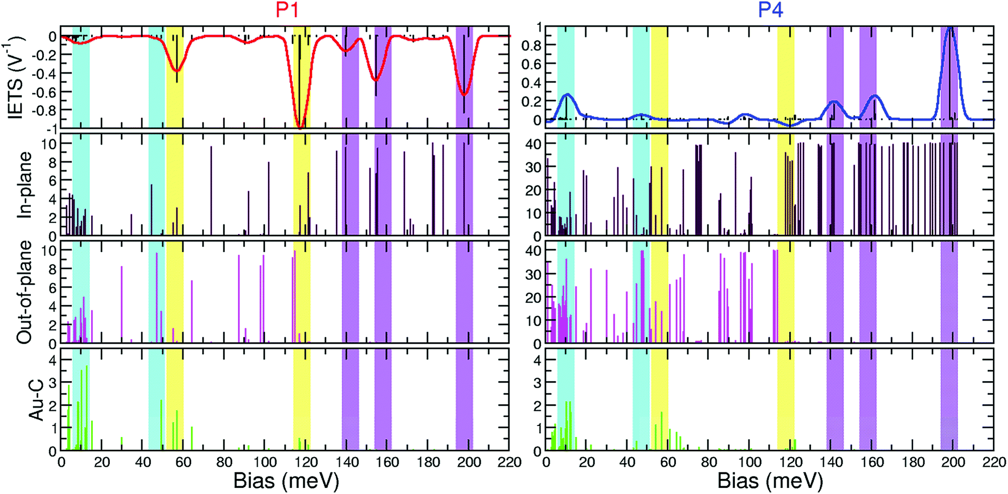 | ||
| Fig. 8 Top panel: IETS signal with scattering rates for active vibrational modes for P1 and P4. Second, third, and fourth panels: in-plane, out-of-plane, and Au–C projections, respectively. Shaded vertical bars highlight low (blue), intermediate (yellow), and high (magenta) energy regions. | ||
For the most important modes (Table 1), the inelastic contribution is overwhelmingly determined by just the single most conducting scattering state in both left- and right-propagating directions. The states are shown in Fig. 3 impinging from below (for states incident from above, the pattern is mirrored around the center of the molecule, given the almost equal potential drop towards both electrodes due to the almost symmetric interface geometry). Since both states are of equal (π) symmetry, selection rules determine that in-plane atomic displacements in the vibrational mode generate the inelastic signal. In addition, since left- and right-incident scattering states are approximately mirror images of each other, the relative displacement in the vibrational mode of equivalent atoms at each interface (with respect to the approximate center of symmetry of the molecule) is important. Modes where these equivalent atoms move in opposite directions tend to be active. Modes where this displacement is in synchrony tend to be dark.43
In the higher energy region, vibrational modes have a strong inelastic signal; dips for the shorter molecules crossing over to peaks for the longer ones. In this energy range, vibrational modes are seen to have mostly in-plane character and the value of the in-plane projection increases linearly with the number of benzene rings, in agreement with our previous analysis, showing that the pattern of the vibrational mode, repeated with molecular length (Fig. 5 and Fig. S1, S2, ESI†), leads to a stronger inelastic signal.
In the intermediate energy region, the character of active modes changes as more rings are added. In particular, we did not find a repeating pattern and in this energy range modes for longer molecules are essentially new modes, different from those of P1. This is the only energy region that keeps an important Au–C contribution that decreases with the number of benzene rings. Importantly, for the longer molecules, the displacement of equivalent atoms in the junction along the modes is in the same direction, which quenches the inelastic signal.43
Finally, in the low energy region, vibrational modes are dark for the shortest molecule P1, and the signal emerges as the length increases to P4. At these low frequencies we find most modes have important out of plane contributions, related to the movement of the C backbone, but also other components as well.
In both the high and the low energy regions we find modes where the vibrational pattern on each ring is repeated as the length of the molecule is increased, the in-plane projection increases linearly with the number of benzene rings and chemically equivalent atoms move in opposite directions showing that these vibrational modes are active.43 Additionally, the in-plane character implies that both left and right scattering states can be of π symmetry, which decay slowly with molecular length. Thus, as the (active) vibrational pattern is repeated with more benzene rings from P1 to P4, the decay of π electronic states is low, and overall the inelastic signal increases with length. At low energies, the in plane component is smaller and so is the IETS signal.
Local and semi-local functionals in DFT are known to lead to errors in the position of molecular frontier levels and underestimation of the gap at the junction. These result in calculated elastic conductance values that generally exceed the measured results.55 In the oligophenyls studied here, the near-resonant regime of P1 is well described by DFT but calculations overestimate conductance for longer molecules.20 In particular, for P2 calculations yield 0.5 G0, the value predicted for a single level with symmetric coupling to undergo a dip to peak transition.36 However, the measured conductance is 0.1 G0, suggesting that peaks in the IETS will be observed in experiments already for this backbone length.
Conclusions
In conclusion, we have carried out first-principles calculations of IETS to investigate and characterize the trends in the inelastic spectra of highly conducting conjugated molecules with covalent Au–C bonds. The elastic conductance changes from near-resonant to the tunneling limit as the molecular length increases from one to four phenyl units, making these molecules an ideal test bed to investigate the onset of inelastic signal. We observed a negative to positive crossover of the inelastic amplitude with increasing length for the highly energetic active C–C stretching modes. We also found that modes with a strong Au–C contribution and electronic coupling between both electrodes were quenched.As the number of benzene monomers was increased, we observed the negative to positive crossover of the inelastic amplitude for the highly energetic active C–C stretching modes, the quenching of modes with significant Au–C components, and the emergence of an inelastic signal from in-plane motions of the carbon backbone. We rationalized and quantified these findings by considering the nature of the vibrational modes and electronic scattering states involved. By simply increasing the number of benzene rings, we were able to tune the interplay between electronic structure and vibrational modes. Our work presents physical insight into these rich phenomena, predicted here for this class of molecules with highly-conducting Au–C bonds.
Conflicts of interest
There are no conflicts to declare.Acknowledgements
We gratefully acknowledge financial support from the Czech Science Foundation (GAČR) under project 15-19672S, the Purkyně Fellowship program of the Academy of Sciences of the Czech Republic, and the European Union's Horizon 2020 research and innovation program under the Marie Skłodowska-Curie Grant Agreement No. 709114. We thank the National Grid Infrastructure MetaCentrum for access to computing and storage facilities provided by the “Projects of Large Research, Development, and Innovations Infrastructures” (CESNET LM2015042) program.References
- K. Moth-Poulsen and T. Bjørnholm, Molecular Electronics with Single Molecules in Solid-State Devices, Nat. Nanotechnol., 2009, 4(9), 551–556 CrossRef CAS PubMed
.
- N. J. Tao, Electron Transport in Molecular Junctions, Nat. Nanotechnol., 2006, 1(3), 173–181 CrossRef CAS PubMed
- S. V. Aradhya and L. Venkataraman, Single-Molecule Junctions beyond Electronic Transport, Nat. Nanotechnol., 2013, 8(6), 399–410 CrossRef CAS PubMed
- A. Nitzan, Electron transmission through molecules and molecular interfaces, Annu. Rev. Phys. Chem., 2001, 52(1), 681–750 CrossRef CAS PubMed
-
S. Datta, Quantum Transport: Atom to Transistor, Cambridge University Press, 2005 Search PubMed
- T. A. Su, M. Neupane, M. L. Steigerwald, L. Venkataraman and C. Nuckolls, Chemical Principles of Single-Molecule Electronics, Nat. Rev. Mater., 2016, 1, 16002 CrossRef CAS
-
D. Bloor, Molecular Electronics, World Scientific, 2nd edn, 1991, vol. 1991 Search PubMed
- Y. S. Park, A. C. Whalley, M. Kamenetska, M. L. Steigerwald, M. S. Hybertsen, C. Nuckolls and L. Venkataraman, Contact Chemistry and Single-Molecule Conductance: A Comparison of Phosphines, Methyl Sulfides, and Amines, J. Am. Chem. Soc., 2007, 129(51), 15768–15769 CrossRef CAS PubMed
- D. J. Mowbray, G. Jones and K. S. Thygesen, Influence of Functional Groups on Charge Transport in Molecular Junctions, J. Chem. Phys., 2008, 128(11), 111103 CrossRef CAS PubMed
- G. Foti and H. Vázquez, Tip-Induced Gating of Molecular Levels in Carbene-Based Junctions, Nanotechnology, 2016, 27(12), 125702 CrossRef PubMed
- J. M. Seminario, C. E. De La Cruz and P. A. Derosa, A Theoretical Analysis of Metal-Molecule Contacts [21], J. Am. Chem. Soc., 2001, 123(23), 5616–5617 CrossRef CAS
- S. Y. Quek, M. Kamenetska, M. L. Steigerwald, H. J. Choi, S. G. Louie, M. S. Hybertsen, J. B. Neaton and L. Venkataraman, Mechanically Controlled Binary Conductance Switching of a Single-Molecule Junction, Nat. Nanotechnol., 2009, 4(4), 230–234 CrossRef CAS PubMed
- M. Kiguchi, T. Ohto, S. Fujii, K. Sugiyasu, S. Nakajima, M. Takeuchi and H. Nakamura, Single Molecular Resistive Switch Obtained via Sliding Multiple Anchoring Points and Varying Effective Wire Length, J. Am. Chem. Soc., 2014, 136(20), 7327–7332 CrossRef CAS PubMed
- L. Venkataraman, J. E. Klare, I. W. Tam, C. Nuckolls, M. S. Hybertsen and M. L. Steigerwald, Single-Molecule Circuits with Well-Defined Molecular Conductance, Nano Lett., 2006, 6(3), 458–462 CrossRef CAS PubMed
- M. A. Reed, C. Zhou, C. J. Muller, T. P. Burgin and J. M. Tour, Conductance of a Molecular Junction, Science, 1997, 278(5336), 252–254 CrossRef CAS
- B. Xu and N. J. Tao, Measurement of Single-Molecule Resistance by Repeated Formation of Molecular Junctions, Science, 2003, 301(5637), 1221–1223 CrossRef CAS PubMed
- J. M. Beebe, V. B. Engelkes, L. L. Miller and C. D. Frisbie, Contact Resistance in Metal-Molecule-Metal Junctions Based on Aliphatic SAMs: Effects of Surface Linker and Metal Work Function, J. Am. Chem. Soc., 2002, 124(38), 11268–11269 CrossRef CAS PubMed
- C. Li, I. Pobelov, T. Wandlowski, A. Bagrets, A. Arnold and F. Evers, Charge Transport in Single Au|Alkanedithiol|Au Junctions: Coordination Geometries and Conformational Degrees of Freedom, J. Am. Chem. Soc., 2008, 130(1), 318–326 CrossRef CAS PubMed
- Z. L. Cheng, R. Skouta, H. Vazquez, J. R. Widawsky, S. Schneebeli, W. Chen, M. S. Hybertsen, R. Breslow and L. Venkataraman, In Situ Formation of Highly Conducting Covalent Au–C Contacts for Single-Molecule Junctions, Nat. Nanotechnol., 2011, 6(6), 353–357 CrossRef CAS PubMed
- W. Chen, J. R. Widawsky, H. Vázquez, S. T. Schneebeli, M. S. Hybertsen, R. Breslow and L. Venkataraman, Highly Conducting π-Conjugated Molecular Junctions Covalently Bonded to Gold Electrodes, J. Am. Chem. Soc., 2011, 133(43), 17160–17163 CrossRef CAS PubMed
- J. R. Widawsky, W. Chen, H. Vázquez, T. Kim, R. Breslow, M. S. Hybertsen and L. Venkataraman, Length-Dependent Thermopower of Highly Conducting Au–C Bonded Single Molecule Junctions, Nano Lett., 2013, 13(6), 2889–2894 CrossRef CAS PubMed
- W. Hong, H. Li, S. X. Liu, Y. Fu, J. Li, V. Kaliginedi, S. Decurtins and T. Wandlowski, Trimethylsilyl-Terminated Oligo(Phenylene Ethynylene)s: An Approach to Single-Molecule Junctions with Covalent Au–C σ-Bonds, J. Am. Chem. Soc., 2012, 134(47), 19425–19431 CrossRef CAS PubMed
- I. J. Olavarria-Contreras, M. L. Perrin, Z. Chen, S. Klyatskaya, M. Ruben and H. S. J. Van Der Zant, C–Au Covalently Bonded Molecular Junctions Using Nonprotected Alkynyl Anchoring Groups, J. Am. Chem. Soc., 2016, 138(27), 8465–8469 CrossRef CAS PubMed
- G. Foti, H. Vázquez, D. Sánchez-Portal, A. Arnau and T. Frederiksen, Identifying Highly Conducting Au–C Links through Inelastic Electron Tunneling Spectroscopy, J. Phys. Chem. C, 2014, 118(46), 27106–27112 CrossRef CAS
- T. Chutora, J. Redondo, B. de la Torre, M. Švec, P. Jelínek and H. Vázquez, Stable Au–C Bonds to the Substrate for Fullerene-Based Nanostructures, Beilstein J. Nanotechnol., 2017, 8(1), 1073–1079 CrossRef CAS PubMed
- N. P. Arasu and H. Vázquez, Direct Au–C Contacts Based on Biphenylene for Single Molecule Circuits, Phys. Chem. Chem. Phys., 2018, 20(15), 10378–10383 RSC
- Y. Sainoo, Y. Kim, T. Okawa, T. Komeda, H. Shigekawa and M. Kawai, Excitation of Molecular Vibrational Modes with Inelastic Scanning Tunneling Microscopy Processes: Examination through Action Spectra of Cis-2-Butene on Pd(110), Phys. Rev. Lett., 2005, 95(24), 246102 CrossRef PubMed
- M. L. Bocquet, H. Lesnard and N. Lorente, Inelastic Spectroscopy Identification of STM-Induced Benzene Dehydrogenation, Phys. Rev. Lett., 2006, 96(9), 96101 CrossRef PubMed
- T. Moriya, O. Nakanishi, A. Yanase and M. Kataoka, Inelastic Electron Tunneling Spectroscopy, Electron Correl. Magn. Narrow-Band Syst., 1981, 29(11), 126–135 Search PubMed
- J. K. Viljas, J. C. Cuevas, F. Pauly and M. Häfner, Electron-Vibration Interaction in Transport through Atomic Gold Wires, Phys. Rev. B: Condens. Matter Mater. Phys., 2005, 72(24), 245415 CrossRef
- T. Frederiksen, M. Paulsson, M. Brandbyge and A. P. Jauho, Inelastic Transport Theory from First Principles: Methodology and Application to Nanoscale Devices, Phys. Rev. B: Condens. Matter Mater. Phys., 2007, 75(20), 205413 CrossRef
- A. Gagliardi, G. Romano, A. Pecchia, A. Di Carlo, T. Frauenheim and T. A. Niehaus, Electron-Phonon Scattering in Molecular Electronics: From Inelastic Electron Tunnelling Spectroscopy to Heating Effects, New J. Phys., 2008, 10(6), 65020 CrossRef
- H. Nakamura, K. Yamashita, A. R. Rocha and S. Sanvito, Efficient Ab Initio Method for Inelastic Transport in Nanoscale Devices: Analysis of Inelastic Electron Tunneling Spectroscopy, Phys. Rev. B: Condens. Matter Mater. Phys., 2008, 78(23), 235420 CrossRef
- M. Bürkle, J. K. Viljas, T. J. Hellmuth, E. Scheer, F. Weigend, G. Schön and F. Pauly, Influence of Vibrations on Electron Transport through Nanoscale Contacts, Phys. Status Solidi B, 2013, 250(11), 2468–2480 CrossRef
- A. Troisi and M. A. Ratner, Molecular Transport Junctions: Propensity Rules for Inelastic Electron Tunneling Spectra, Nano Lett., 2006, 6(8), 1784–1788 CrossRef CAS PubMed
- M. Paulsson, T. Frederiksen, H. Ueba, N. Lorente and M. Brandbyge, Unified Description of Inelastic Propensity Rules for Electron Transport through Nanoscale Junctions, Phys. Rev. Lett., 2008, 100(22), 226604 CrossRef PubMed
- N. Lorente, M. Persson, L. J. Lauhon and W. Ho, Symmetry Selection Rules for Vibrationally Inelastic Tunneling, Phys. Rev. Lett., 2001, 86(12), 2593–2596 CrossRef CAS PubMed
- M. Paulsson, T. Frederiksen and M. Brandbyge, Modeling Inelastic Phonon Scattering in Atomic- and Molecular-Wire Junctions, Phys. Rev. B: Condens. Matter Mater. Phys., 2005, 72(20), 201101 CrossRef
- A. Troisi and M. A. Ratner, Molecular Transport Junctions: Propensity Rules for Inelastic Electron Tunneling Spectra, Nano Lett., 2006, 6(8), 1784–1788 CrossRef CAS PubMed
- A. Garcia-Lekue, D. Sanchez-Portal, A. Arnau and T. Frederiksen, Simulation of Inelastic Electron Tunneling Spectroscopy of Single Molecules with Functionalized Tips, Phys. Rev. B: Condens. Matter Mater. Phys., 2011, 83(15), 155417 CrossRef
- A. Gagliardi, G. C. Solomon, A. Pecchia, T. Frauenheim, A. Di Carlo, N. S. Hush and J. R. Reimers, A Priori Method for Propensity Rules for Inelastic Electron Tunneling Spectroscopy of Single-Molecule Conduction, Phys. Rev. B: Condens. Matter Mater. Phys., 2007, 75(17), 174306 CrossRef
- Z. Jiang, H. Wang, S. Sanvito and S. Hou, Revisiting the Inelastic Electron Tunneling Spectroscopy of Single Hydrogen Atom Adsorbed on the Cu(100) Surface, J. Chem. Phys., 2015, 143(23), 234709 CrossRef PubMed
- G. Foti and H. Vázquez, Mapping the Intramolecular Contributions to the Inelastic Electron Tunneling Signal of a Molecular Junction, Phys. Rev. B: Condens. Matter Mater. Phys., 2016, 94(4), 45418 CrossRef
- N. Agrat, C. Untiedt, G. Rubio-Bollinger and S. Vieira, Electron Transport and Phonons in Atomic Wires, Chem. Phys., 2002, 281(2–3), 231–234 CrossRef
- L. De La Vega, A. Martín-Rodero, N. Agraït and A. L. Yeyati, Universal Features of Electron-Phonon Interactions in Atomic Wires, Phys. Rev. B: Condens. Matter Mater. Phys., 2006, 73(7), 75428 CrossRef
- O. Tal, M. Krieger, B. Leerink and J. M. Van Ruitenbeek, Electron-Vibration Interaction in Single-Molecule Junctions: From Contact to Tunneling Regimes, Phys. Rev. Lett., 2008, 100(19), 196804 CrossRef CAS PubMed
- Y. Kim, T. Pietsch, A. Erbe, W. Belzig and E. Scheer, Benzenedithiol: A Broad-Range Single-Channel Molecular Conductor, Nano Lett., 2011, 11(9), 3734–3738 CrossRef CAS PubMed
- S. Kaneko, C. Motta, G. P. Brivio and M. Kiguchi, Mechanically Controllable Bi-Stable States in a Highly Conductive Single Pyrazine Molecular Junction, Nanotechnology, 2013, 24(31), 315201 CrossRef PubMed
- Y. Kim, A. Garcia-Lekue, D. Sysoiev, T. Frederiksen, U. Groth and E. Scheer, Charge Transport in Azobenzene-Based Single-Molecule Junctions, Phys. Rev. Lett., 2012, 109(22), 226801 CrossRef PubMed
- J. M. Soler, E. Artacho, J. D. Gale, A. Garcia, J. Junquera, P. Ordejón and D. Sánchez-Portal, The SIESTA Method for Ab Initio Order-N Materials Simulation, J. Phys.: Condens. Matter, 2002, 14(11), 2745 CrossRef CAS
-
M. Brandbyge; J. L. Mozos; P. Ordejón; J. Taylor and K. Stokbro, Density-Functional Method for Nonequilibrium Electron Transport, American Physical Society, 2002, vol. 65, pp. 1654011–1654017 Search PubMed
- J. P. Perdew, K. Burke and M. Ernzerhof, Generalized Gradient Approximation Made Simple, Phys. Rev. Lett., 1996, 77(18), 3865–3868 CrossRef CAS PubMed
- G. Foti, D. Sánchez-Portal, A. Arnau and T. Frederiksen, Role of k -Point Sampling in the Supercell Approach to Inelastic Electron Tunneling Spectroscopy Simulations of Molecular Monolayers, Phys. Rev. B: Condens. Matter Mater. Phys., 2015, 91(3), 35434 CrossRef
- L. Venkataraman, J. E. Klare, C. Nuckolls, M. S. Hybertsen and M. L. Steigerwald, Dependence of Single-Molecule Junction Conductance on Molecular Conformation, Nature, 2006, 442(7105), 904–907 CrossRef CAS PubMed
- M. Strange and K. S. Thygesen, Towards Quantitative Accuracy in First-Principles Transport Calculations: The GW Method Applied to Alkane/Gold Junctions, Beilstein J. Nanotechnol., 2011, 2(1), 746–754 CrossRef CAS PubMed
Footnotes |
| † Electronic supplementary information (ESI) available. See DOI: 10.1039/c8cp06290k |
| ‡ Present address: Donostia International Physics Center (DIPC), Paseo Manuel de Lardizabal 4, Donostia-San Sebastián 20018, Spain. |
| This journal is © the Owner Societies 2019 |