
Coupling effect of van der Waals, centrifugal, and frictional forces on a GHz rotation–translation nano-convertor†
Bo
Song
a,
Kun
Cai
 *ab,
Jiao
Shi
ad,
Yi Min
Xie
b and
Qinghua
Qin
c
*ab,
Jiao
Shi
ad,
Yi Min
Xie
b and
Qinghua
Qin
c
aCollege of Water Resources and Architectural Engineering, Northwest A&F University, Yangling 712100, China. E-mail: kun.cai@rmit.edu.au
bCentre for Innovative Structures and Materials, School of Engineering, RMIT University, Melbourne 3083, Australia
cResearch School of Engineering, The Australian National University, ACT 2601, Australia
dState Key Laboratory of Structural Analysis for Industrial Equipment, Dalian University of Technology, Dalian 116024, China
First published on 27th November 2018
Abstract
A nano rotation–translation convertor with a deformable rotor is presented, and the dynamic responses of the system are investigated considering the coupling among the van der Waals (vdW), centrifugal and frictional forces. When an input rotational frequency (ω) is applied at one end of the rotor, the other end exhibits a translational motion, which is an output of the system and depends on both the geometry of the system and the forces applied on the deformable part (DP) of the rotor. When centrifugal force is stronger than vdW force, the DP deforms by accompanying the translation of the rotor. It is found that the translational displacement is stable and controllable on the condition that ω is in an interval. If ω exceeds an allowable value, the rotor exhibits unstable eccentric rotation. The system may collapse with the rotor escaping from the stators due to the strong centrifugal force in eccentric rotation. In a practical design, the interval of ω can be found for a system with controllable output translation.
1 Introduction
With the rapid development in nanotechnology, miniaturization of devices from the microscale to nanoscale becomes feasible.1 The concepts of typical nanodevices, such as the resonator,2–5 oscillator,6–11 and rotary motor,12–16 have been proposed for over a decade, and some of them have been realized in nanofabrication. For example, a nano-resonator has been used as a balance to measure the mass of a small molecule.4,5 The oscillator has a potential application in memory as an on–off. A few models for the rotary nanomotor have been proposed, which may be applied to drive the motion of a nano vehicle.On the nanoscale, the motion of a component in a system depends on the external forces exerted. One of the forces is van der Waals (vdW) force.17 Although not as strong as ionic or covalent bonds, vdW force always plays an important role in the mechanical properties, electrical transport properties, and the dynamic response of the nanodevices at interfaces between components.18–22 Hertal et al.23 investigated the significant deformation of carbon nanotubes (CNTs) by surface vdW forces that were generated between the nanotube and the substrate. Huang et al.24 found that a strain gradient in graphene can induce a non-zero net vdW force, which is sufficient to actuate the directional movement of molecular mass on the graphene surface. Besides, self-assembly of low dimensional materials is often controlled by vdW force.25–29
When relative sliding occurs between two components in a device, frictional force will affect the sliding state. In particular, the value of frictional force on the nanoscale increases with the relative sliding speed.8,16,30–33 Friction even becomes a major factor in the dynamic response of such devices as nano-oscillators or nanomotors. Centrifugal force only appears on a rotating component. For example, in a rotary nanomotor, the atoms on the rotor are subjected to centrifugal force, which is proportional to the square of the rotational speed. At gigahertz rotation, the rotor may be damaged due to heavy centrifugal force on the atoms.34–38
In this study, a model for a rotation–translation nano-convertor is proposed potentially as a nano on–off or a sensor for measuring the rotational speed of the rotor. Considering the excellent mechanical strength of sp2 carbon materials, e.g., carbon nanotubes39 and graphene,40 and the extremely low friction between neighbouring layers,32,33,39–43 we choose CNTs as the rotor and stators in the system. Like origami,44 four graphene ribbons are used to form a deformable part (DP) for connecting both the input part and the output part of the rotors (Fig. 1). Different from a traditional transmission system,45,46 as a rotational speed is applied on the input part of the rotor, it will also drive the rotation of the remaining parts. During rotation, the centrifugal force on the DP causes deformation of the DP and synchronously produces translation of the output part. The effects of the vdW, centrifugal and frictional forces on the dynamic behavior of the system are investigated by molecular dynamics simulations.
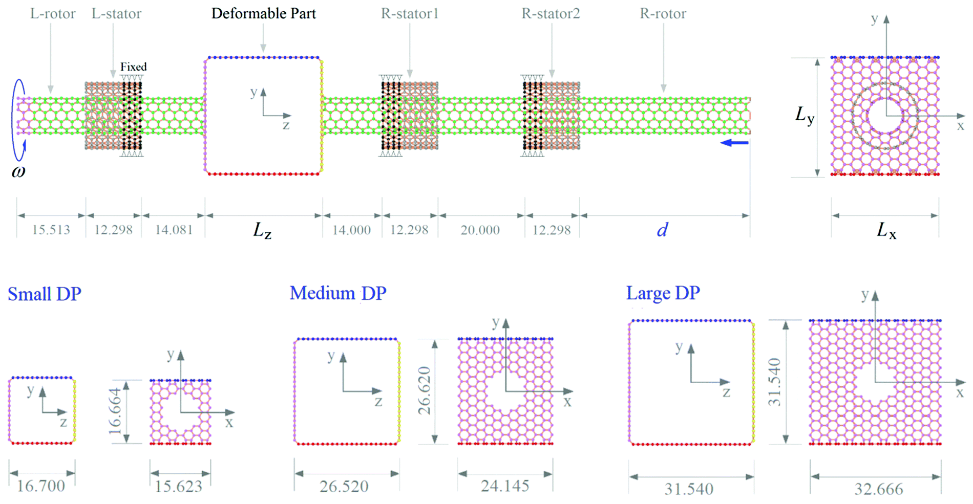 | ||
| Fig. 1 Schematic of a rotation–translation convertor with a deformable carbon rotor. At the left end of the L-rotor (the input part), an input rotational frequency, i.e., ω, is exerted. “d” is the distance between the right edges of the R-rotor and the R-stator2, and it is the output of the system. Dimensions of the deformable part (DP) are labeled as Lx, Ly, and Lz, respectively, with the unit of Å. Three DPs with different sizes are considered. | ||
2 Model and methodology
2.1 Model of the rotary device
In this work, the model shown in Fig. 1 is adopted to illustrate the vdW effect and the centrifugal effect on the nanoscale. In the model, a deformable part (DP) made from graphene ribbons is used to connect the L-rotor and the R-rotor made from CNTs. Three CNT-based stators are fixed to constrain the motion of the rotors. At the left end of the L-rotor, a constant rotational frequency, ω, is input. The distance between the right ends of the R-stator2 and the R-rotor is output to show the axial motion of the R-rotor. The detailed parameters are listed in Table 1.| Component | Chirality | Radius | Length | Ring/layer | Number of atoms |
|---|---|---|---|---|---|
| L-rotor | (6,6) | 4.068 | 41.811 | 35 | 420C |
| R-rotor | (6,6) | 4.068 | 95.921 | 80 | 948C + 12H |
| L-stator | (11,11) | 7.458 | 12.298 | 11 | 242C |
| R-stator1 | (11,11) | 7.458 | 12.298 | 11 | 242C |
| R-stator2 | (11,11) | 7.458 | 12.298 | 11 | 242C |
| Small DP | 15.623(x) × 16.664(y) × 16.700(z) | 4 | 104C × 2(up + down) + 80C × 2(left + right) | ||
| Medium DP | 24.145(x) × 26.620(y) × 26.520(z) | 4 | 252C × 2(up + down) + 228C × 2(left + right) | ||
| Large DP | 32.666(x) × 31.540(y) × 31.540(z) | 4 | 400C × 2(up + down) + 376C × 2(left + right) | ||
2.2 Methods
The molecular dynamics simulation approach was adopted to find the deformation of configuration of the rotor during rotating. Simulations were accomplished using the open code LAMMPS.47 The interaction among atoms in the carbon/hydrogen system is described by the AIREBO potential.48 In each simulation, the initial configuration of the system is modified by minimizing its potential energy. Further, some atoms are fixed in their degrees of freedom, e.g., three rings of atoms on the left end of the rotor, four rings of atoms on each stator (Fig. 1). The next step is to relax the system using a canonical (NVT) ensemble for 100 ps with a timestep of 0.5 fs. After relaxation using the Nose–Hoover thermostat,49,50 a specified rotational frequency is exerted on the L-rotor at the atoms that were previously fixed in relaxation. During rotating, the timestep is set as 1 fs, and some essential physical quantities, e.g., variation of potential energy (VPE), centrifugal force of the DP, and displacement of the right end of the R-rotor, are recorded for analysis. The value of VPE can be calculated by subtracting the initial value of potential energy of the component from its current value.Temperature effects were considered by considering the system at low temperature (e.g., 8 K), room temperature (e.g., 300 K), and high temperature (e.g., 500 K). The input rotational frequency of the L-rotor, i.e., ω, was varied from 10 GHz to 100 GHz or higher if necessary.
To show the vdW effect on the deformation and output of the system, the VPE of the DP is defined and calculated using the following equation,
| VPE(t) = PE(t) − PE(t0), | (1) |
| PE(t) = PREBO(t) + PTorsion(t) + PL-J(t). | (2) |
The interaction cut-off distance for the L-J potential is set as 1.02 nm.
3 Results and discussion
3.1 Variation of configuration of the medium DP
As deformation of the DP can be evaluated by the value of VPE, the histories of the VPE of the medium DP under different conditions are first drawn in Fig. 2. From the convergent values of the VPE curves, a conclusion can be made, in general, that the value of VPE increases when the input rotational frequency (ω) increases. The fluctuation of VPE depends on both the input rotation and temperature. The fluctuation decreases and tends to be stable after ∼5 ns in most cases. The fluctuation of VPE demonstrates the variation of the DP's configuration. Higher fluctuation, e.g., in the first 1 ns, means the DP undergoes large deformation. In particular, the DP is under axial torsion due to friction from the stators. For example, for the DP with ω = 60 GHz at 300 K, its configuration at 15 ps in Fig. 3a is obviously different from the initial one (0 ps), but it is similar to that at 83 ps. In particular, the DP becomes a narrow ring, in which the two sides of the ring attach. For the narrow ring, it cannot deform further. This means that the rotor rotating at 60 GHz or higher frequency should have the same configuration, i.e., a narrow ring. | ||
| Fig. 2 Histories of VPE of the medium DP with different rotational frequency at different temperatures: (a) 8 K, (b) 300 K, and (c) 500 K. | ||
 | ||
| Fig. 3 Variation of configurations of the medium DP in the system under different conditions. (a) Axial translation of the right rotor when rotating with ω = 60 GHz at 300 K. (b) Stable configurations of the DP under different conditions. (c) Formation of nine bonds in the DP when rotating with ω = 70 GHz at 500 K. (d) Attraction of the R-stator1 exerted on the DP with ω = 10 GHz at 300 K. (e) Collapse process of the system with ω = 100 GHz at 500 K. | ||
At 8 K, the fluctuation of VPE tends to be less than 0.2 eV, which is far less than that at 300 K or 500 K. This is because thermal vibration of the atoms in the DP at higher temperature contributes more to VPE. Meanwhile, it should be mentioned that the fluctuations of VPE at 40 GHz and 50 GHz are more drastic than those of the remaining cases. The reason will be given later.
By comparing the stable values of VPE at a specific temperature, e.g., at 8 K, we find that the values are not always higher when the input rotational frequency is higher. For example, the stable values of VPE at ω = 60 GHz and 70 GHz are much larger than those at 80 GHz and 90 GHz. Similarly, at 300 K, the value of VPE at 60 GHz is the highest among the ten cases. The reason is that the DP becomes a narrow ring, the two sides of the ring attach together, which leads to a decreasing potential energy of the DP at 80 GHz or 90 GHz rotation (Fig. 3b). Once the DP becomes a narrow ring, the two sides are difficult to separate, and the DP cannot deform with ω. Hence, 70 GHz can be considered as the upper limit of the system with a deformable rotor at this temperature.
Another phenomenon is that VPE becomes negative in some cases, e.g., ω = 70 GHz at 300 K and 500 K, and 60 GHz at 500 K. We know that the edge of the DP comprises unsaturated carbon atoms, which are easily bonded together.34 For a pair of unsaturated carbon atoms being bonded together, the decreasing potential energy is ∼4.75 eV (see the first item in the right part of eqn (2)). According to the snapshot of Fig. 3c, the medium DP with ω = 70 GHz at 500 K is bonded together by nine new C–C bonds. In particular, the sharp drops of VPE in Fig. 2c illustrate the bonding process, i.e., each drop means one or more new bonds being generated. In this case, there are nine new bonds, but ten new bonds are generated in the same DP with ω = 60 GHz at the same temperature. Self-bonding of the DP depends on two major factors, i.e., a stator-friction-induced higher torque moment (Mst in Fig. 3d) that leads to the approach of the unsaturated carbon atoms in the DP and a relatively low centrifugal force that cannot pull the deformed DP into a narrow ring. Hence, self-bonding occurs at ω = 60 or 70 GHz, but not at ω = 80 or 90 GHz.
The final characteristics of the VPE curves are that the values jump up quickly within the first 1 ns when ω = 100 GHz at 8 K and 500 K. Before giving the reason, we recall that the value of VPE only depends on the deformation of the DP. From the snapshot at 83 ps in Fig. 3a, the DP has become a narrow ring, and the distance between the middle parts of its two vertical sides is nearly 0.34 nm, which means that the ring has no more space for further deformation in the present situation. Hence, the drastic jumping up of VPE at 100 GHz at both temperatures must be caused by the other deformation of the rotor. Fig. 3e shows the variation process of the system configuration when ω = 100 GHz at 500 K. It indicates that the system collapses within 260 ps. The jump up of VPE is caused by further deformation of the DP together with the L-/R-rotor after escaping from the right stators (snapshot at 245 ps in Fig. 3e).
3.2 Rotary inertia of the medium DP during rotating
To quantitatively illustrate the deformation of the medium DP during rotating, the value of rotary inertia of the DP about the z-axis is calculated by the following equation,| Jz = ∑mi × (ri + di)2, | (3) |
 | ||
| Fig. 4 Rotary inertia of the medium DP under different conditions at different temperatures: (a) 8 K, (b) 300 K, and (c) 500 K. | ||
Firstly, in some cases, e.g., ω = 60 or 70 GHz at 8 K, the value of rotary inertia is the highest among the first nine cases, i.e., ω < 100 GHz. A similar phenomenon also appears at 500 K. The ring becomes very narrow (Fig. 3b), most atoms move away from the z-axis, i.e., di > 0 (in eqn (3)), and this results in the highest value of rotary inertia.
Secondly, the value of rotary inertia exhibits sudden jumps when ω = 10 GHz at 300 K (Fig. 4b) or 500 K (Fig. 4c). For example, in Fig. 4b, the rotary inertia of the DP jumps from 18.39 kg nm2 at 4610 ps up to 22.63 kg nm2 at 4640 ps and down to 18.46 kg nm2 at 4820 ps. By observing the snapshots in Fig. 3d, we know that the DP deforms during the period, and most atoms in the DP are further away from the z-axis at 4640 ps than at 4610 ps. According to eqn (3), the value of rotary inertia at 4640 ps is higher than that at 4610 ps.
Finally, the fluctuation of rotary inertia at 20 GHz ≤ ω ≤ 50 GHz is much stronger than the remaining cases. In particular, at 8 K, the fluctuation of rotary inertia of the DP can be neglected when ω = 80 or 90 GHz. The reason for this is that the configuration of the DP with the input rotational frequency between 20 GHz and 50 GHz varies periodically. But, the configuration with ω = 90 GHz is very stable during rotating. This demonstrated that the input rotational frequency in the interval, i.e., 20–50 GHz, can produce a breathing state of the DP's configuration (Movie 1, ESI†).
3.3 Centrifugal force on the rotary medium DP
The centrifugal force on the DP can be calculated using the following equation, i.e.,| Fc = ∑Fci = ∑miωi2 × ri = mDP × ω2 × rc, | (4) |
Deformation of the DP leads to variations of the VPE and the rotary inertia. But, it does not mean that the centrifugal force on the DP varies simultaneously. If, for example, the rotor together with the DP has an ideal rotation, i.e., the rotating part has symmetric deformation about the z-axis without eccentricity, the value of centrifugal force on the DP should be zero. If the DP has a stable configuration and a constant eccentricity, the value of centrifugal force should be a positive constant. However, in an atomic system, random thermal vibration of the atom always exists. During rotating of the DP, thermal vibration of atoms always exists. Hence, even if the rotating part looks symmetric about the z-axis, thermal vibration still leads to eccentricity of the DP. Under high speed rotating, non-zero centrifugal force appears. The spectrum of centrifugal force on the DP under different conditions is drawn in Fig. 5.
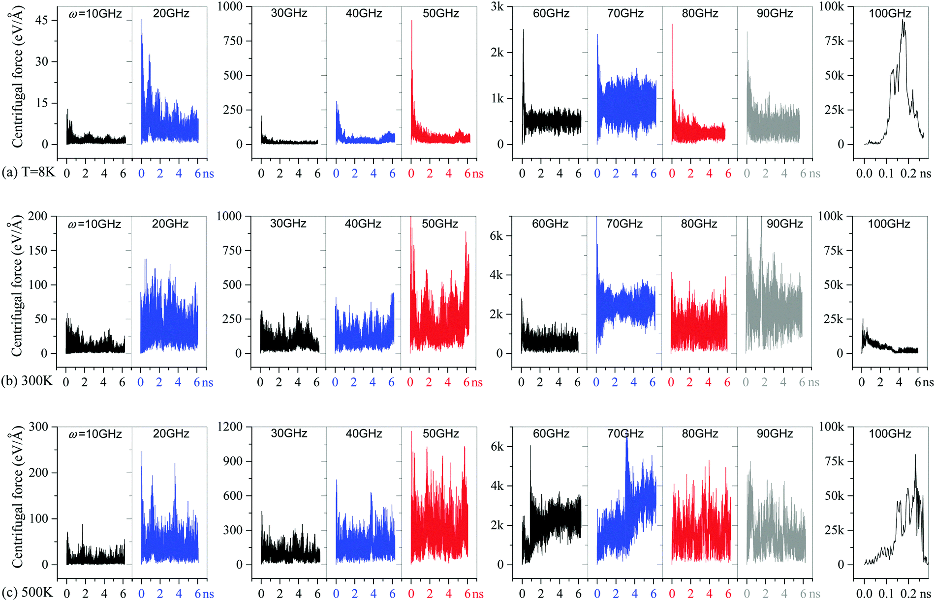 | ||
| Fig. 5 Spectrum of centrifugal force on the medium DP with different rotational frequencies at different temperatures: (a) 8 K, (b) 300 K, and (c) 500 K. | ||
At lower speeds of rotation, the DP is subjected to a very small centrifugal force. For example, at 8 K, the centrifugal force on the medium DP is not higher than 45 eV Å−1 when ω is not higher than 20 GHz. However, when ω increases to 30 GHz, the peak value of centrifugal force is over 200 eV Å−1. But, before ω approaches 50 GHz, the maximum of centrifugal force does not exceed 1000 eV Å−1. When ω is between 60 GHz and 90 GHz, the peak value of the centrifugal force is over 2000 eV Å−1. At 100 GHz, the system collapses, and the maximum of the centrifugal force is more than ten times that at 90 GHz. The magnitude of centrifugal force increases slightly with the temperature.
The maximum value of centrifugal force, which appears in the first 1 ns, indicates the maximum eccentricity of the DP. After reaching the peak value, the centrifugal force tends to fluctuate in a narrow range. In this way, the state of the DP can be illustrated by the mean value and the standard deviation of the centrifugal force at this stage. For example, the mean value indicates the stable eccentric rotation of the DP. But the standard deviation reflects two facts. One is the periodic axial waving of the two edges of the narrow DP. The other is the periodic radial vibration of the centroid of the DP.
It can be found that the maximum of the mean value at a specific temperature appears when ω = 70 GHz. The reason for this is that the DP is undergoing eccentric rotating, i.e., the two slim tubes connected by the DP bend during rotating (Movie 2, ESI†). This means that the eccentricity of the DP, i.e., the magnitude of rc in eqn (4), increases obviously. This does not occur in any other cases when the system does not collapse. Hence, 70 GHz can be considered as an input rotational frequency that is very close to the eigen frequency with respect to the current system. The DP will have higher eccentricity when rotating with the eigen frequency.
Now, the reason for the collapse of the rotating part with ω = 100 GHz at 8 K or 500 K can be explained as follows: the strong centrifugal force pulls the DP away from the rotating axis. Due to the left end of the L-rotor being fixed for input rotation, the right part, i.e., the R-rotor, is under tension toward the left (snapshot at 151 ps in Fig. 3e). When the axial stretching force can overcome the potential barriers at the right edges of the R-stator2 and the R-rotor (snapshot at 235 ps in Fig. 3e), the right end of the R-rotor will continue to move left (snapshot at 255 ps in Fig. 3e) until complete collapse occurs (snapshot at 260 ps in Fig. 3e). Here, 100 GHz can be considered as the upper limit of input rotational frequency for the system at this temperature.
3.4 Axial translation of the R-rotor
In the model shown in Fig. 1, the R-rotor connects with the DP. When the DP deforms, the left end of the R-rotor will move with it. During rotating at high speed, the DP becomes a narrow ring (Fig. 3b), and the R-rotor moves left (the snapshots at 15/75/83 ps in Fig. 3a). Large axial displacement of the right end of the R-rotor occurs simultaneously. A nanodevice, e.g., an on–off, can be made according to the present model with a variable value of d. For example, when d > 4 nm, the device is in the “on” state, and it is in the “off” state when d < 2.5 nm. Controlling the value of d is significant for such a device.Fig. 6 illustrates the variation of d, i.e., the distance between the right ends of the R-stator2 and the R-rotor, during rotating with the DP under different conditions. In general, the value of d decreases with increasing ω. At 8 K, the values of d with ω = 60 GHz and 70 GHz are the lowest and remain unchanged soon after no more than 1 ns. After that, the DP has no chance to return to its original configuration. Hence, the value of d fluctuates slightly. Similarly, at 500 K, the value of d shows a sudden jump up when ω = 60 or 70 GHz due to the generation of the new bonds in the rotating DP (e.g., Fig. 3c). Before self-bonding, the DP becomes a very narrow ring, which leads to a lower value of d. Once the unsaturated atoms on one side of the narrow ring bond together, those internal atoms neighboring the new bonded atoms are subjected to strong repulsion. Hence, the other side of the ring becomes a wide oval. This is the reason why the value of d jumps up suddenly.
 | ||
| Fig. 6 Axial motion of the R-rotor under different conditions at different temperatures: (a) 8 K, (b) 300 K, and (c) 500 K. | ||
The minimum of d appears when ω = 80 GHz at 500 K, when the DP becomes a very narrow ring (Fig. 3b). Even when the rotor has a higher value of ω, the DP cannot deform further. If ω is between 20 GHz and 50 GHz, the value of d fluctuates with an amplitude of ∼0.5 nm. At a lower temperature, e.g., 300 K, the amplitude of fluctuation is lower. The sudden jumps occurring at 300 K or 500 K when ω = 10 GHz are caused by the sharp variation of the DP configuration (Fig. 3d). Under centrifugal force (Fc in Fig. 3d), the DP tends to become a narrow ring with a very small distance between the two rotors. But the vdW effect, which generates the bending stiffness of the ribbon that forms the DP, and the attraction from the R-stator1 (Fig. 3d) result in a larger distance between the two rotors, i.e., a larger vdW force (FvdW) leads to a higher value of d. If centrifugal force is higher, d reduces. In this case, the DP is in a critical equilibrium state under the centrifugal and the vdW forces.
It is necessary to demonstrate that the final stable value of d depends obviously on the input rotational frequency but slightly on the temperature if the system is in stable rotation but no new bond is being generated in the DP. Fig. 7 indicates that the value of d decreases linearly with increasing ω between 20 GHz and 50 GHz. When a specific value of d between 4 nm and 4.4 nm is required, the input rotational frequency can be designed accurately.
 | ||
| Fig. 7 The curves of d versus ω at different temperatures. Initial value of d is 3.909 nm. | ||
3.5 Size effect of DP on the output of the system
As aforementioned, only the medium DP was involved. Fig. 6 and 7 indicate that the minimum of d (>0) depends on the size of the DP. To show the effect of the size of the DP on the critical value of ω and the stable value of d, three models of the DP shown in Fig. 1 were considered at 300 K.After a series of tests, we found that the small DP collapses when ω > 190 GHz (Fig. 8a), which is higher than 110 GHz of the medium DP. But, the large DP remains stable only when ω is no higher than 60 GHz. Otherwise, e.g., at ω = 70 GHz, the rotor system collapses (Fig. 8b). These states can be read from the curves in Fig. 8. This means that a larger DP can maintain stable rotation only at a lower input speed. Without considering the collapse of the DP, e.g., by constraining the maximum axial of the R-rotor, the maximum deformation of the DP will also determine the maximum axial displacement of the R-rotor.
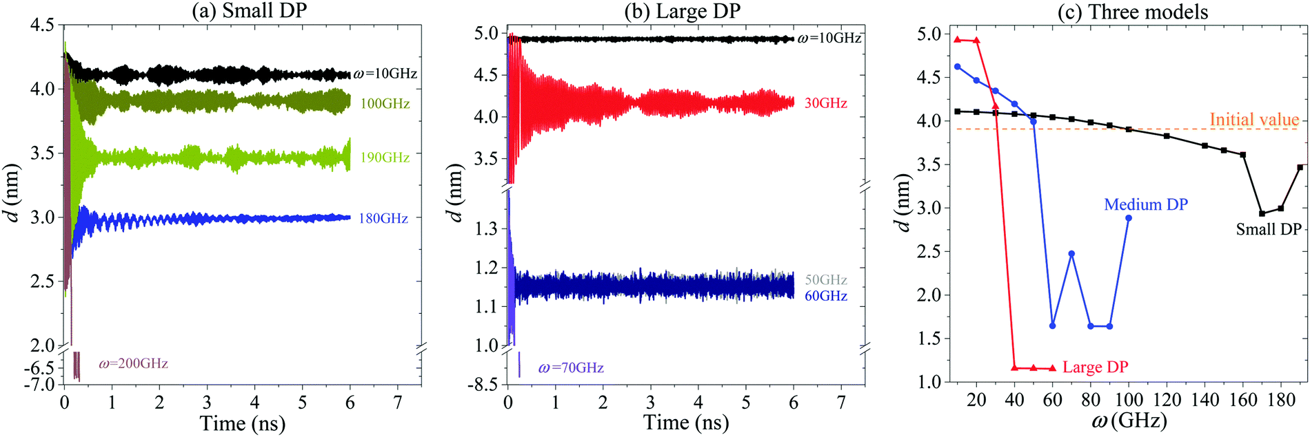 | ||
| Fig. 8 Axial translation of the R-rotor when connected to three different DPs: (a) small DP, (b) large DP, and (c) curves of d vs. ω for the small, medium and large DPs. | ||
In each curve in Fig. 8c, there is a sharp decrease of d. For example, it occurs between 160 GHz and 170 GHz for the system with the small DP, or between 50 GHz and 60 GHz for the system with the medium DP, or between 30 GHz and 40 GHz for the system with the large DP. The two values form a gap that divides the states of the DP into stable rotation and unstable rotation. In a stable rotation, eccentricity of the DP is small and majorly caused by irregular deformation of the DP. In an unstable rotation, the DP is in one of three different states. The first state is that the DP may be in an obvious eccentric rotation owing to bending deformation of the two rotors. Second, self-bonding of the DP may occur. The final state is that the DP becomes a narrow ring.
4 Conclusions
The effects of vdW, frictional and centrifugal forces exerted on the deformable rotor of a rotation–translation convertor are evaluated using molecular dynamics simulations. For the deformable part (DP) in the rotor, its configuration is mainly determined by the input rotational frequency ω. The axial translation of the right rotor, as an output of the system, depends on the state of the DP's configuration. In general, the value of ω determines the state of the DP. Conclusions can be drawn based on the DP states, i.e.,(1) Low speed rotation (e.g., ω < 20 GHz of the medium DP): In this state, the centrifugal force is weaker than the vdW force, and the DP undergoes small deformation during rotating. The axial translation of the rotor does not occur.
(2) Medium speed rotation (e.g., 20 GHz ≤ ω ≤ 50 GHz of the medium DP): The rotor has a stable rotation, and the axial motion of the rotor increases linearly with ω. The deformation of DP is controllable.
(3) Mid-high speed rotation (e.g., 60 GHz ≤ ω ≤ 70 GHz of the medium DP): The deformation of the DP in the rotor is unstable due to strong friction from the stators and relatively low centrifugal force, and the DP can be either a wide oval, or a narrow ring, or having self-bonding.
(4) High speed rotation (e.g., 80 GHz ≤ ω ≤ 90 GHz of the medium DP): The deformation of the DP is strongly dependent on the centrifugal force, and slightly on the vdW force or the friction from stators. The DP becomes a narrow ring, and rotation is stable. Axial translational motion of the rotor remains unchanged with respect to ω.
(5) Collapse (e.g., ω ≥ 110 GHz of the medium DP): Eccentric rotation appears easily, and strong centrifugal force on the deformed DP pulls the rotor away from the right stators until the system collapses.
Briefly, if the system is not broken, the rotation of the DP can be divided into stable rotation and unstable rotation states. In a stable rotation, eccentricity of the DP is small and majorly caused by irregular deformation of the DP. The output translation is stable and controllable. In an unstable rotation, the DP might be in one of three different states, i.e., obvious eccentric rotation owing to bending deformation of the two rotors, self-bonding of the DP, and the DP becoming a narrow ring.
Conflicts of interest
The authors declare that there is no conflict of interest.Acknowledgements
Financial support from the National Key Research and Development Plan, China (Grant No.: 2017YFC0405102), and Open project of State Key Laboratory of Structural Analysis for Industrial Equipment, China (Grant No.: GZ111) are acknowledged.References
- S. Lin, E. K. Lee, N. Nguyen and M. Khine, Thermally-induced miniaturization for micro- and nanofabrication: progress and updates, Lab Chip, 2014, 14, 3475–3488 RSC.
- P. Poncharal, Z. L. Wang, D. Ugarte and W. A. Heer, Electrostatic deflections and electromechanical resonances of carbon nanotubes, Science, 1999, 283, 1513–1516 CrossRef CAS PubMed.
- D. Garcia-Sanchez, P. A. San, M. J. Esplandiu, F. Perez-Murano, L. Forró, A. Aguasca and A. Bachtold, Mechanical detection of carbon nanotube resonator vibrations, Phys. Rev. Lett., 2007, 99, 085501 CrossRef CAS PubMed.
- J. Chaste, A. Eichler, J. Moser, G. Ceballos, R. Rurali and A. Bachtold, A nanomechanical mass sensor with yoctogram resolution, Nat. Nanotechnol., 2012, 7, 301–304 CrossRef CAS PubMed.
- S. Adhikari and R. Chowdhury, Zeptogram sensing from gigahertz vibration: Graphene based nanosensor, Phys. E, 2012, 44, 1528–1534 CrossRef CAS.
- Q. Zheng and Q. Jiang, Multiwalled carbon nanotubes as gigahertz oscillators, Phys. Rev. Lett., 2002, 88, 045503 CrossRef PubMed.
- S. B. Legoas, V. R. Coluci, S. F. Braga, P. Z. Coura, S. O. Dantas and D. S. Galvao, Molecular-dynamics simulations of carbon nanotubes as gigahertz oscillators, Phys. Rev. Lett., 2003, 90, 055504 CrossRef CAS PubMed.
- W. L. Guo, Y. F. Guo, H. J. Gao, Q. S. Zheng and W. Y. Zhong, Energy dissipation in gigahertz oscillators from multiwalled carbon nanotubes, Phys. Rev. Lett., 2003, 91, 125501 CrossRef PubMed.
- V. Sazonova, Y. Yaish, H. Ustunel, D. Roundy, T. A. Arias and P. L. Mceuen, A tunable carbon nanotube electromechanical oscillator, Nature, 2004, 431, 284–287 CrossRef CAS PubMed.
- Z. Zhang and T. Li, Ultrafast nano-oscillators based on interlayer-bridged carbon nanoscrolls, Nanoscale Res. Lett., 2011, 6, 470 CrossRef PubMed.
- K. Cai, H. Yin, Q. H. Qin and Y. Li, Self-excited oscillation of rotating double-walled carbon nanotubes, Nano Lett., 2014, 14, 2558–2562 CrossRef CAS PubMed.
- B. Bourlon, C. Glattli, A. Bachtold and L. Forro, Carbon nanotube based bearing for rotational motions, Nano Lett., 2004, 4, 709–712 CrossRef CAS.
- R. Eelkema, M. M. Pollard, J. Vicario, N. Katsonis, B. S. Ramon, C. W. M. Bastiaansen, D. J. Broer and B. L. Feringa, Nanomotor rotates microscale objects, Nature, 2006, 440, 163 CrossRef CAS PubMed.
- A. Barreiro, R. Rurali, E. R. Hernandez, J. Moser, T. Pichler, L. Forro and A. Bachtold, Subnanometer motion of cargoes driven by thermal gradients along carbon nanotubes, Science, 2008, 320, 775–778 CrossRef CAS PubMed.
- B. Y. Wang, L. Vukovic and P. Kral, Nanoscale rotary motors driven by electron tunneling, Phys. Rev. Lett., 2008, 101, 186808 CrossRef PubMed.
- K. Cai, J. Z. Yu, L. N. Liu, J. Shi and Q. H. Qin, Rotation measurements of a thermally driven rotary nanomotor with a spring wing, Phys. Chem. Chem. Phys., 2016, 18, 22478–22486 RSC.
- J. E. Jones, On the determination of molecular fields. II. From the equation of state of a gas, Proc. R. Soc. London, Ser. A, 1924, 106, 463–477 CrossRef CAS.
- D. H. Cho, L. Wang, J. S. Kim, G. H. Lee, E. S. Kim, S. Lee, S. Y. Lee, J. Hone and C. Lee, Effect of surface morphology on friction of graphene on various substrates, Nanoscale, 2013, 5, 3063–3069 RSC.
- A. Farajpour, M. Dehghany and A. R. Shahidi, Surface and nonlocal effects on the axisymmetric buckling of circular graphene sheets in thermal environment, Composites, Part B, 2013, 50, 333–343 CrossRef CAS.
- X. Q. Zhang, H. Li and K. M. Liew, The structures and electrical transport properties of germanium nanowires encapsulated in carbon nanotubes, J. Appl. Phys., 2007, 102, 073709 CrossRef.
- H. Y. Tang, H. F. Ye, H. W. Zhang and Y. G. Zheng, Wrapping of nanoparticles by the cell membrane: the role of interactions between the nanoparticles, Soft Matter, 2015, 11, 8674 RSC.
- A. A. Chialvo and L. Vlcek, Can we describe graphene confined water structures as overlapping of approaching graphene–water interfacial structures?, J. Phys. Chem. C, 2016, 120, 7553–7561 CrossRef CAS.
- T. Hertel, R. E. Walkup and P. Avouris, Deformation of carbon nanotubes by surface van der Waals forces, Phys. Rev. B: Condens. Matter Mater. Phys., 1998, 58, 13870 CrossRef CAS.
- Y. Huang, S. Zhu and T. Li, Directional transport of molecular mass on graphene by straining, Extreme Mech. Lett., 2014, 1, 83–89 CrossRef.
- Y. F. Li, H. Q. Yu, H. Li, C. G. An, K. Zhang, K. M. Liew and X. F. Liu, How do metal/graphene self-assemble into core–shelled composite nanostructures, J. Phys. Chem. C, 2011, 115, 6229–6234 CrossRef CAS.
- V. B. Shenoy and D. H. Gracias, Self-folding thin-film materials: From nanopolyhedra to graphene origami, MRS Bull., 2012, 37, 847–854 CrossRef CAS.
- S. Zhu and T. Li, Hydrogenation enabled scrolling of graphene, J. Phys. D: Appl. Phys., 2013, 46(7), 075301 CrossRef.
- J. W. Feng, H. M. Ding and Y. Q. Ma, Self-assembly of fullerenes and graphene flake: A molecular dynamics study, Carbon, 2015, 90, 34–43 CrossRef CAS.
- K. Cai, L. N. Liu, J. Shi and Q. H. Qin, Winding a nanotube from black phosphorus nanoribbon onto a CNT at low temperature: A molecular dynamics study, Mater. Des., 2017, 121, 406–413 CrossRef CAS.
- K. Cai, H. F. Cai, J. Shi and Q. H. Qin, A nano universal joint made from curved double-walled carbon nanotubes, Appl. Phys. Lett., 2015, 106, 241907 CrossRef.
- Z. R. Guo, T. C. Chang, X. M. Guo and H. J. Gao, Thermal-induced edge barriers and forces in interlayer interaction of concentric carbon nanotubes, Phys. Rev. Lett., 2011, 107, 105502 CrossRef PubMed.
- J. Cumings and A. Zettl, Low-friction nanoscale linear bearing realized from multiwall carbon nanotubes, Science, 2000, 289, 602–604 CrossRef CAS PubMed.
- E. H. Cook, M. J. Buehler and Z. S. Spakovszky, Mechanism of friction in rotating carbon nanotube bearings, J. Mech. Phys. Solids, 2013, 61, 652–673 CrossRef CAS.
- K. Cai, J. Z. Yu, H. Yin and Q. H. Qin, Sudden stoppage of rotor in a thermally driven rotatry motor made from double-walled carbon nanotubes, Nanotechnology, 2015, 26, 095702 CrossRef CAS PubMed.
- J. Shi, H. Yin, J. Yu, L. Liu and K. Cai, Configuration transition between graphene and nanoscroll using kinetic energy injecting method, Comput. Mater. Sci., 2016, 125(146), 153 Search PubMed.
- K. Cai, J. Z. Yu, J. Wan, H. Yin, J. Shi and Q. H. Qin, Configuration jumps of rotor in a nanomotor from carbon nanostructures, Carbon, 2016, 101, 168–176 CrossRef CAS.
- J. Shi, H. F. Cai, K. Cai and Q. H. Qin, Dynamic behavior of a black phosphorus and carbon nanotube composite system, J. Phys. D: Appl. Phys., 2017, 50, 025304 CrossRef.
- J. Ahn, Z. J. Xu, J. Bang, Y. H. Deng, T. M. Hoang, Q. K. Han, R. M. Ma and T. C. Li, Optically levitated nanodumbbell torsion balance and GHz nanomechanical rotor, Phys. Rev. Lett., 2018, 121, 033603 CrossRef PubMed.
- M. M. J. Treacy, T. W. Ebbesen and J. M. Gibson, Exceptionally high Young's modulus observed for individual carbon nanotubes, Nature, 1996, 381, 678–680 CrossRef CAS.
- C. G. Lee, X. D. Wei, J. W. Kysar and J. Hone, Measurement of the elastic properties and intrinsic strength of monolayer graphene, Science, 2008, 321, 385–388 CrossRef CAS PubMed.
- J. Servantie and P. Gaspard, Rotational dynamics and friction in double-walled carbon nanotubes, Phys. Rev. Lett., 2006, 97, 186106 CrossRef CAS PubMed.
- A. Kis, K. Jensen, S. Aloni, W. Mickelson and A. Zettl, Interlayer forces and ultralow sliding friction in multiwalled carbon nanotubes, Phys. Rev. Lett., 2006, 97, 025501 CrossRef CAS PubMed.
- R. F. Zhang, Z. Y. Ning, Y. Y. Zhang, Q. S. Zheng, Q. Chen, H. H. Xie, Q. Zhang, W. Z. Qian and F. Wei, Superlubricity in centimetres-long double-walled carbon nanotubes under ambient conditions, Nat. Nanotechnol., 2013, 8, 912–916 CrossRef CAS PubMed.
- S. Zhu and T. Li, Hydrogenation-assisted graphene origami and its application in programmable molecular mass uptake, storage, and release, ACS Nano, 2014, 8(3), 2864–2872 CrossRef CAS PubMed.
- K. Cai, H. Yin, N. Wei, Z. Chen and J. Shi, A stable high-speed rotational transmission system based on nanotubes, Appl. Phys. Lett., 2015, 106, 021909 CrossRef.
- K. Cai, H. F. Cai, L. Ren, J. Shi and Q. H. Qin, Over-speeding rotational transmission of a carbon nanotube-based bearing, J. Phys. Chem. C, 2016, 120, 5797–5803 CrossRef CAS.
- S. Plimpton, Fast parallel algorithms for short-range molecular dynamics, J. Comput. Phys., 1995, 117, 1–19 CrossRef CAS.
- S. J. Stuart, A. B. Tutein and J. A. Harrison, A reactive potential for hydrocarbons with intermolecular interactions, J. Chem. Phys., 2000, 112, 6472–6486 CrossRef CAS.
- S. Nosé, A unified formulation of the constant temperature molecular dynamics methods, J. Chem. Phys., 1984, 81, 511–519 CrossRef.
- W. G. Hoover, Canonical dynamics: Equilibrium phase-space distributions, Phys. Rev. A: At., Mol., Opt. Phys., 1985, 31, 1695–1697 CrossRef.
Footnote |
| † Electronic supplementary information (ESI) available: Movie 1 – medium DP at 500 K-input 50 GHz-[5, 5.18]ns.avi. Movie 2 – medium DP at 500 K-input 70 GHz-[3.02, 3.09]ns.avi. See DOI: 10.1039/c8cp06013d |
| This journal is © the Owner Societies 2019 |