
 Open Access Article
 This Open Access Article is licensed under a Creative Commons Attribution-Non Commercial 3.0 Unported Licence
Calcium vanadate sub-microfibers as highly reversible host cathode material for aqueous zinc-ion batteries†
Xu
Liu
ab,
Huang
Zhang
 ab,
Dorin
Geiger
c,
Jin
Han
ab,
Alberto
Varzi
ab,
Ute
Kaiser
c,
Arianna
Moretti
*ab and
Stefano
Passerini
*ab
ab,
Dorin
Geiger
c,
Jin
Han
ab,
Alberto
Varzi
ab,
Ute
Kaiser
c,
Arianna
Moretti
*ab and
Stefano
Passerini
*ab
aHelmholtz Institute Ulm (HIU), Electrochemistry I, 89081 Ulm, Germany
bKarlsruhe Institute of Technology (KIT), 76021 Karlsruhe, Germany. E-mail: stefano.passerini@kit.edu; arianna.moretti@kit.edu
cCentral Facility of Electron Microscopy, Electron Microscopy Group of Materials Science, Ulm University, Albert-Einstein-Allee 11, D-89081 Ulm, Germany
First published on 8th January 2019
Abstract
For the first time, CaV6O16·3H2O (CVO), synthesized via a highly efficient and fast microwave reaction, is used as a cathode material for aqueous zinc-ion batteries. Ex situ X-ray diffraction confirms the structure of this material to be stable upon reversible Zn2+ intercalation, due to its large interlayer distance (8.08 Å). The pillaring effect of calcium makes the as-prepared CVO an excellent Zn2+ cation host.
Since their commercialization in 1991, lithium-ion batteries (LIBs) have rapidly developed, conquering the market of portable electronics and, currently, electric vehicles.1 However, the potential cost increase due to limited supply of lithium and, especially, cobalt is pushing the interest towards alternative secondary battery chemistries relying on more abundant elements.2 Furthermore, the commonly used carbonate-based electrolytes possess high cell voltages, however, being highly flammable and toxic and requiring stringent conditions for manufacturing, safe operation and recycling.3 Replacing organic solvent-based electrolytes with aqueous ones is an effective strategy to overcome such drawbacks. In this context, aqueous zinc batteries (AZBs) are a promising complementary technology to LIBs. Zinc is an abundant element produced on a large-scale,4 which, in its metallic form, can be directly used as an anode in aqueous electrolyte batteries. Having a redox potential of −0.76 V vs. SHE, which is comparable to those of other commonly used anode materials in aqueous systems, e.g. LiTi2(PO4)3 (−0.52 V vs. SHE) and NaTi2(PO4)3 (−0.6 V vs. SHE), but a high volumetric theoretical capacity (5854 mA h cm−3), Zn is an extremely appealing anode material.5
Although rechargeable AZBs are appealing, they are still in their infancy and their development is hindered by the restricted choice of cathode materials that often display limited cycle life, poor rate capability, and structural instability upon multivalent cation insertion. Polyanionic compounds and Prussian blue analogues suffer from low specific capacity, while manganese-based oxides have a short lifespan due to severe manganese dissolution.6 Nazar et al. reported a high-capacity and long-life rechargeable AZB based on Zn0.25V2O5·nH2O.7 Since then, a series of layered vanadium-based oxides and sulfides have been investigated.8 In general, these compounds deliver high specific capacity (>300 mA h g−1) when the composition and morphology are carefully designed. For example, as reported by Pang et al., H2V3O8 nanowires (diameter is 50–100 nm) anchored on the surface of graphene sheets exhibit a high capacity of 394 mA h g−1 at 100 mA g−1.9 The high specific capacity of vanadium oxides compensates for their relatively low operating voltage (around 0.8 V vs. Zn2+/Zn). However, although displaying a better cycling stability than manganese oxides, vanadium oxides still need further improvement to meet the standard of practical use. Previous studies have shown that adopting a suitable metal cation as a pillaring agent can effectively stabilize the vanadium slab, reducing, or even fully avoiding the structural collapse upon Li+ and Na+ intercalation/de-intercalation.10 This strategy was extended to AZBs and, so far, focused on the effect of alkali metal cations (e.g., LiV3O8, Na0.25V2O5, Na2V6O16, KV3O8, K0.25V2O5, K2V6O16, and K2V8O21),11 while the effect of alkaline-earth metal cations was less investigated.
CaV6O16·3H2O (CVO) is a typical vanadium-bronze mineral. The calcium cations are located in the interlayer space and coordinated by oxygens from the two vanadium slabs, facing each other, and by oxygens belonging to bound water molecules (see the inset in Fig. 1).12 Hence, the Ca cations may act as pillaring agents stabilizing the vanadium oxide structure, like the alkali metal cations do. Moreover, CVO has a larger interlayer distance compared with alkali-metal vanadium bronzes with formulae MxV2O5, MV3O8, MV6O15, and M2V6O16 (M = Li, Na, or K) (Table S1, ESI,† summarizes the interlayer distance of these vanadium bronzes), which favours the intercalation of the shuttling ions. Actually, CVO has been reported as a cathode for LIBs, delivering a specific capacity of 252 mA h g−1 at 100 mA g−1, and showing no fading after 200 cycles at 200 mA g−1.13 However, to the best of our knowledge, the reversible zinc storage properties of CVO have not been studied yet. Furthermore, the reported preparation methods for CVO are complex or time-consuming, necessitating several steps to obtain CVO. For example, Zhang et al. used electrochemical deposition to synthesize a precursor, which, upon an additional hydrothermal treatment, led to the synthesis of CVO.13 Li et al. prepared CVO via thermal hydrolysis of pre-prepared Ca10V6O25.14 Even the simplest surfactant-assisted hydrothermal method still needs the reactor to be set at 160 °C for several hours (10 h).15
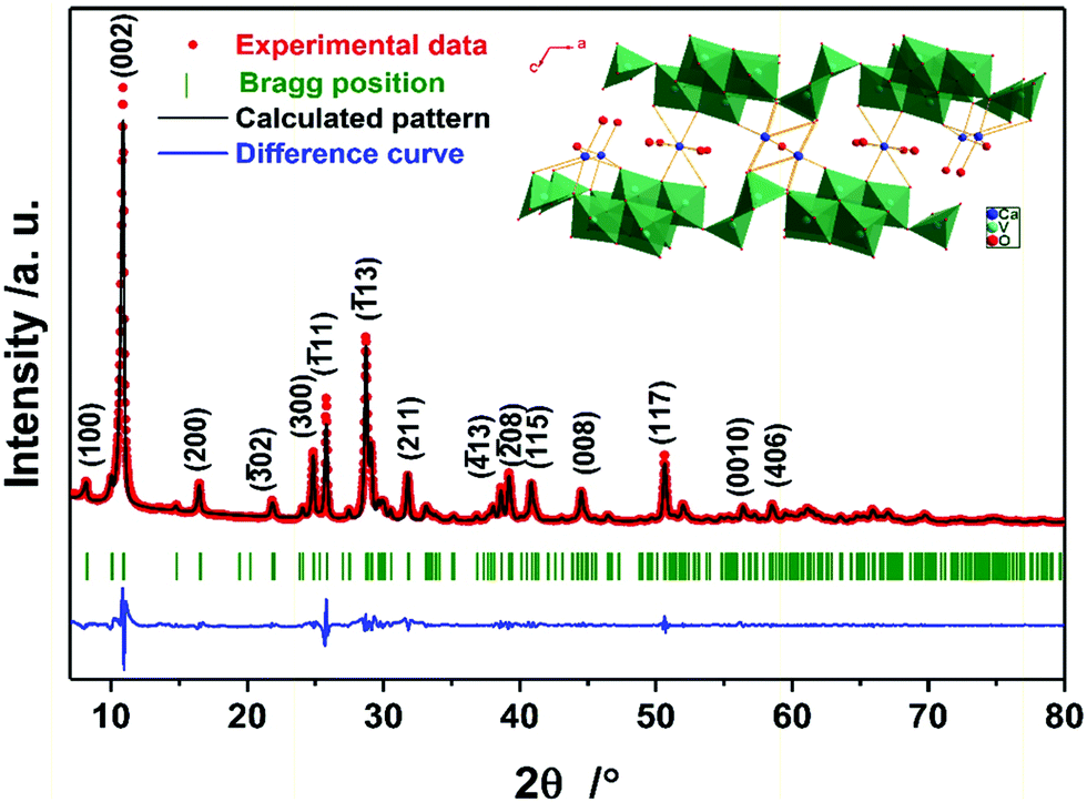 | ||
| Fig. 1 Summary of the Rietveld refinement of the as-prepared CVO. The experimental data, calculated pattern, difference curve, and Bragg position are shown in red, black, blue, and olive, respectively. The inset shows the crystal structure model projected along [010]. | ||
In this communication, we report a new, very fast and highly efficient synthesis of CVO based on the microwave reaction, and explore, for the first time, its zinc storage properties in aqueous electrolyte. In our typical preparation, 1 mmol Ca(CH3COO)2 and 2 mmol V2O5 were mixed in 20 mL ultrapure water. Through microwave dielectric heating, CVO was obtained after only 2 h at 180 °C. Notably, only 105 seconds were needed to reach 180 °C, after which a power as low as 20 W was sufficient to keep the temperature constant (see Fig. S1, ESI†). Therefore, our method offers clear advantages over previous preparation procedures in terms of easiness and time and cost reduction. More details on the material synthesis and further processing can be found in the ESI.†
The structure of the as-prepared sample was confirmed by powder X-ray diffraction (PXRD). Fig. 1 shows the summary of the Rietveld refinement (Rwp = 11.14%, the obtained structural parameters are shown in Table S2, ESI†), demonstrating that the compound is phase-pure CVO, whose structure is depicted in the inset of Fig. 1. According to the refined peak position of the (002) plane, the interlayer distance is calculated to be 8.08 Å, which is much larger than those of the initial material, V2O5 (4.38 Å, PDF 41-1426), and other vanadium bronzes incorporating alkali metals (see Table S1, ESI†). Thermogravimetric analysis (TGA) was carried out to detect the amount of intercalated water (see Fig. S2, ESI†), which was 8.4 wt%, corresponding to the theoretical content in the formula CaV6O16·3H2O (8.2 wt%).13
As seen in Fig. 2a, the as-prepared CVO was composed of uniform fibers longer than 100 μm and with a diameter in the range of hundreds of nanometers. The latter sub-micrometric dimension is certainly beneficial for shortening the solid-state diffusion path of Zn2+.16 Nevertheless, the diameter of the as-prepared CVO is still larger than those of other vanadium oxides reported for AZBs,10 which, as discussed in the following, may affect its electrochemical performance. Additionally, the valence state of vanadium in CVO is 5+, which could result in a high electronic resistance within a single wire.17Fig. 2b shows the EDX elemental mapping of the CVO micro-wires. The distribution of the three elements (Ca, V, and O) in the CVO material was found to be uniform and in good agreement with the secondary electron image taken on the same region. The transmission electron microscopy (TEM) image shown in Fig. 2c further reveals that the fiber is not uniform. Furthermore, the parallel boundaries along the edge indicate that it consists of slabs. The inset displays a typical [0![[1 with combining macron]](https://www.rsc.org/images/entities/char_0031_0304.gif) 0] electron diffraction pattern, demonstrating that the fiber is a single crystal with the slabs stacking along the same direction. Finally, the high-resolution TEM (HRTEM) image (Fig. 2d) shows well-developed lattice fringes with an interplanar spacing of 1.08 nm, which is identical to that of the (100) plane of CVO.
0] electron diffraction pattern, demonstrating that the fiber is a single crystal with the slabs stacking along the same direction. Finally, the high-resolution TEM (HRTEM) image (Fig. 2d) shows well-developed lattice fringes with an interplanar spacing of 1.08 nm, which is identical to that of the (100) plane of CVO.
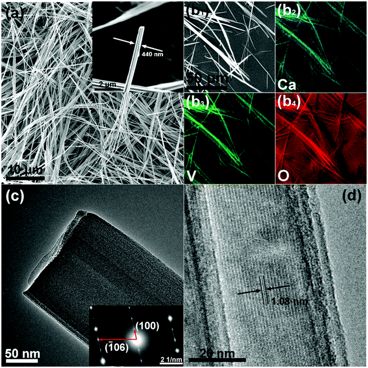 | ||
| Fig. 2 (a) SEM images of the as-prepared CVO. (b) SEM image and the corresponding EDX elemental mapping images of Ca, V, and O. (c) TEM image of the as-prepared CVO and the corresponding electron diffraction pattern. (d) HRTEM image of the as-prepared CVO. | ||
The electrochemical properties of CVO were examined using Zn//CVO coin cells employing the 3 m aqueous solution of Zn(CF3SO3)2 as the electrolyte. Further information about the cell setup and measurement conditions is reported in the ESI.†
The cyclic voltammetry (CV) profile obtained at a scanning rate of 0.05 mV s−1 is shown in Fig. 3a. Two pairs of reversible redox peaks, located at 0.65 V and 0.98 V in the cathodic scan (peak 1 and 2), and at 0.48 V and 0.76 V in the anodic scan (peak 3 and 4), indicate that Zn2+ intercalation into CaV6O16·3H2O occurs through a multistep process.18 With a faster scan rate (from 0.1 to 0.5 mV s−1) the peak separation increased (the voltammograms are displayed in Fig. S3a, ESI†). According to the empirical power-law relationship with the scan rate:
| i = avb | (1) |
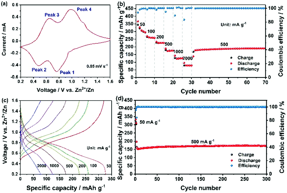 | ||
| Fig. 3 Electrochemical performance of the as-fabricated CVO electrode. (a) CV curve at 0.05 mV s−1. (b) Specific capacity and coulombic efficiency obtained at different current densities. (c) Charge–discharge profiles at different current densities. (d) Specific capacity and coulombic efficiency upon extensive cycling at 500 mA g−1. The first two activation cycles were performed at 50 mA g−1. | ||
For further details, the log![[thin space (1/6-em)]](https://www.rsc.org/images/entities/char_2009.gif) (i) vs. log(v) curves are displayed in Fig. S3b (ESI†). These values indicate that the capacity of the as-prepared CVO is controlled by both capacitive (b = 1) and diffusive (b = 0.5) processes. Noticeably, they are lower than those reported for other layered vanadium oxides and sulfides, such as VO2, K2V6O16, V2O5, and VS2, which is due to the relatively larger dimensions of CVO reducing the capacitive contribution.11,19
(i) vs. log(v) curves are displayed in Fig. S3b (ESI†). These values indicate that the capacity of the as-prepared CVO is controlled by both capacitive (b = 1) and diffusive (b = 0.5) processes. Noticeably, they are lower than those reported for other layered vanadium oxides and sulfides, such as VO2, K2V6O16, V2O5, and VS2, which is due to the relatively larger dimensions of CVO reducing the capacitive contribution.11,19
Galvanostatic discharge/charge cycles at different current densities are reported in Fig. 3b. In the first cycle at 50 mA g−1, the discharge capacity reached 367 mA h g−1, while the coulombic efficiency was 93.69% and gradually increased upon cycling. Since the size of the microwave synthesized CVO wires was rather large, the diffusion-controlled process is expected to be predominant. Thus, the resulting high specific capacity must result from the large interlayer distance in CVO. The irreversible capacity observed in the first cycle could arise from two possible parasitic reactions involving the reduction of dissolved O2 and the salt anion (CF3SO3−). In fact, although the electrolyte was de-aereated by bubbling N2 in it for one hour, the cell was assembled in an ambient atmosphere, leading to some inevitable O2 in the cell. The reduction of oxygen during the discharge process could consume some electrons and contribute to the irreversible capacity.20 Regarding the salt anion, CF3SO3−, its reduction in concentrated NaCF3SO3 electrolytes has been reported.21 However, the efficiency rapidly increased to 99.72% at the 4th cycle, demonstrating, overall, a good reversibility of the multivalent cation intercalation process. Because of the larger grain size and, possibly, lower electronic conductivity, the specific capacity at high specific current is not superior to those of other reported vanadium oxides, leaving considerable room for optimization. Nevertheless, at a specific current of 1 A g−1, a specific capacity higher than 125 mA h g−1 was achieved. The corresponding charge–discharge curves are shown in Fig. 3c. The plateaus matched well with the redox peaks in Fig. 3a. When the specific current was brought back to 500 mA g−1, the cell recovered its capacity without any loss, implying the integrity of the CVO structure. The evaluation of the long-term cycling is displayed in Fig. 3d. At the 4th cycle, the discharge capacity was 160 mA h g−1, gradually increasing to 170 mA h g−1 and then remaining stable for the whole duration of the test (i.e., 300 cycles). The cell voltage vs. capacity during a few, selected charge–discharge cycles is displayed in Fig. S4 (ESI†).
The electrochemical properties of several cathode materials for AZBs are compared in Table S3 (ESI†). The specific capacity of the as-prepared CVO is much higher than that of polyanionic compounds, Prussian blue analogues, and manganese-based oxides, and it exceeds that of a series of other vanadium-based oxides as well as sulfides. Furthermore, CVO displays excellent capacity retention, e.g., better than most of the reported cathode materials for AZBs.
To investigate the Zn-cation storage mechanism, the ex situ XRD characterization of CVO electrodes was performed. Fig. 4a displays the diffractograms obtained at different states of charge and discharge during the first cycle. The corresponding charge/discharge profile is shown in Fig. 4b. Notably, the initial interlayer distance (7.4 Å) was smaller than that of the pristine powder. This can be attributed to the partial loss of the water molecules intercalated in the interlayer due to the extensive drying process after electrode fabrication. Upon Zn2+ intercalation, the (002) peak gradually shifted to higher degrees, suggesting the decrease of the interlayer distance from the initial value (7.4 Å) to 6.8 Å at the fully intercalated state. This is due to the intercalated Zn2+ cations attracting the adjacent, negatively charged V–O slabs. When Zn2+ was extracted, the (002) peak shifted back to lower degrees. The final interlayer distance was very close to the initial value. This reveals the excellent reversibility of Zn2+ (de-)intercalation in the layered structure of CVO. Interestingly, a set of new peaks, marked by grey boxes in Fig. 4a, appeared during Zn2+ intercalation and disappeared upon Zn2+ release.16 No other peaks evolved at higher angles (Fig. S5, ESI†). It is reasonable to think that these peaks originated from the intercalated Zn2+. To gain more information about the intercalated CVO, SEM and TEM were applied to the fully discharged sample. As shown in Fig. 4c, the fiber-like morphology is retained. The distribution of zinc element matches well with the secondary electron image, indicating the presence of zinc in the intercalated fiber, i.e., confirming the proposed intercalation mechanism. Observing the electron diffraction pattern, one can conclude that the zinc intercalated CVO fiber is a single crystal. The calculated interlayer spacings and the HRTEM image (see Fig. S6, ESI†) imply that the lattice constants have quite large difference after the intercalation of zinc. Considering the regular and reversible shift of the (002) peak during the charge/discharge process, one can infer that the intercalated compound still retains some structural features of pristine CVO. A deep analysis is ongoing to clarify the structural evolutions occurring in the CVO electrode during cell cycling.
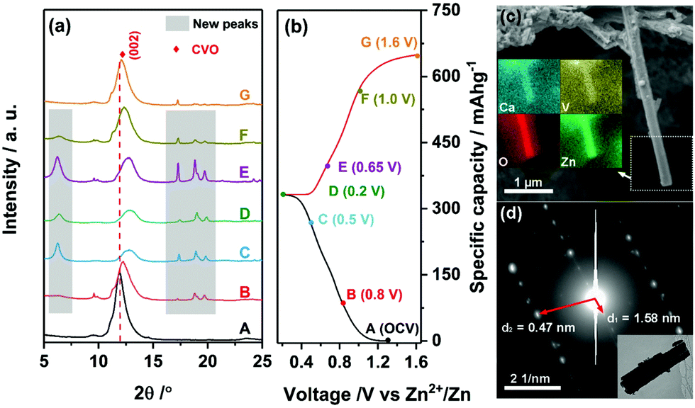 | ||
| Fig. 4 (a) Ex situ XRD patterns of the as-fabricated CVO electrodes at various states of the first cycle, and (b) the corresponding voltage profile. (c) SEM image and the corresponding EDX elemental mapping images of the CVO fiber discharged to 0.2 V. (d) Electron diffraction pattern of the CVO fiber discharged to 0.2 V and the corresponding TEM image of the fiber. | ||
In conclusion, ultra-long CVO micro-wires were obtained with a highly efficient and very fast microwave reaction. Owing to the large interlayer distance and pillaring effect of calcium, the electrode material reversibly intercalated up to 4.5 equivalents of Zn2+ per mole of CVO, delivering high specific capacity with excellent capacity retention. Ex situ XRD measurement confirmed the reversibility of the process, the high structural stability of CVO. Although we can already foresee further optimization of the synthesis conditions (e.g., a decrease of CVO wire diameter, introduce mixed vanadium valence states or electronically conductive materials), CVO prepared by the microwave reaction is a promising cathode for aqueous zinc-ion batteries and a potential host for other multivalent cations.
X. L., H. Z., and J. H. gratefully acknowledge financial support from the China Scholarship Council (CSC). Financial support from the Helmholtz Association is also acknowledged.
Conflicts of interest
There are no conflicts to declare.Notes and references
- A. Moretti, F. Maroni, I. Osada, F. Nobili and S. Passerini, ChemElectroChem, 2015, 2, 529 CrossRef CAS.
- C. Vaalma, D. Buchholz, M. Weil and S. Passerini, Nat. Rev. Mater., 2018, 3, 18013 CrossRef.
- Z. Peng, Q. L. Wei, S. S. Tan, P. He, W. Luo, Q. Y. An and L. Q. Mai, Chem. Commun., 2018, 54, 4041 RSC.
- X. G. Zhang, Corrosion and Electrochemistry of Zinc, Springer, 1996 Search PubMed.
- H. B. Wang, K. L. Huang, Y. Q. Zeng, S. Yang and L. Q. Chen, Electrochim. Acta, 2007, 52, 3280 CrossRef CAS; D. Bin, F. Wang, A. C. Tamirat, S. M. Suo, Y. G. Wang, C. S. Wang and Y. Y. Xia, Adv. Energy Mater., 2018, 8, 1703008 CrossRef.
- G. L. Li, Z. Yang, Y. Liang, C. H. Jin, W. Huang, X. L. Ding and Y. H. Huang, Nano Energy, 2016, 25, 211 CrossRef CAS; R. Trócoli and F. L. Mantia, ChemSusChem, 2015, 8, 481 CrossRef PubMed; S. Zhao, B. Han, D. T. Zhang, Q. Huang, L. Xiao, L. Chen, D. G. Ivey, Y. D. Deng and W. F. Wei, J. Mater. Chem. A, 2018, 6, 5733 RSC.
- D. P. Kundu, B. D. Adams, V. Duffort, S. H. Vajargah and L. F. Nazar, Nat. Energy, 2016, 1, 16119 CrossRef CAS.
- M. Song, H. Tan, D. L. Chao and H. J. Fan, Adv. Funct. Mater., 2018, 28, 1802564 CrossRef.
- Q. Pang, C. L. Sun, Y. H. Yu, K. N. Zhao, Z. Y. Zhang, P. M. Voyles, G. Chen, Y. J. Wei and X. D. Wang, Adv. Energy Mater., 2018, 8, 1800144 CrossRef.
- J. S. Meng, Z. A. Liu, C. J. Niu, X. M. Xu, X. Liu, G. B. Zhang, X. P. Wang, M. Huang, Y. Yu and L. Q. Mai, J. Mater. Chem. A, 2016, 4, 4893 RSC; Y. L. Zhao, C. H. Han, J. W. Yang, J. Su, X. M. Xu, S. Li, L. Xu, R. P. Fang, H. Jiang, X. D. Zou, B. Song, L. Q. Mai and Q. J. Zhang, Nano Lett., 2015, 15, 2180 CrossRef CAS PubMed; J. H. Yao, Y. W. Li, R. C. Massé, E. Uchaker and G. Z. Cao, Energy Storage Mater., 2018, 11, 205 CrossRef.
- M. H. Alfaruqi, V. Mathew, J. J. Song, S. J. Kim, S. Islam, D. T. Pham, J. Jo, S. Kim, J. P. Baboo, Z. L. Xiu, K. S. Lee, Y. K. Sun and J. Kim, Chem. Mater., 2017, 29, 1684 CrossRef CAS; Y. S. Cai, F. Liu, Z. G. Luo, G. Z. Fang, J. Zhou, A. Q. Pan and S. Q. Liang, Energy Storage Mater., 2018, 13, 168 CrossRef; P. He, G. B. Zhang, X. B. Liao, M. Y. Yan, X. Xu, Q. Y. An, J. Liu and L. Mai, Adv. Energy Mater., 2018, 8, 1702463 CrossRef; V. Soundharrajan, B. Sambandam, S. Kim, M. H. Alfaruqi, D. Y. Putro, J. Jo, S. Kim, V. Mathew, Y. K. Sun and J. Kim, Nano Lett., 2018, 18, 2402 CrossRef PubMed; P. Hu, T. Zhu, X. P. Wang, X. J. Wei, M. Y. Yan, J. T. Li, W. Luo, W. Yang, W. C. Zhang, L. Zhou, Z. Q. Zhou and L. Q. Mai, Nano Lett., 2018, 18, 1758 CrossRef PubMed; B. Sambandam, V. Soundharrajan, S. Kim, M. H. Alfaruqi, J. Jo, S. Kim, V. Mathew, Y. K. Sun and J. Kim, J. Mater. Chem. A, 2018, 6, 15530 RSC; B. Y. Tang, G. Z. Fang, J. Zhou, L. B. Wang, Y. P. Lei, C. Wang, T. Q. Lin, Y. Tang and S. Q. Liang, Nano Energy, 2018, 51, 579 CrossRef.
- M. A. Cooper, F. C. Hawthorne, V. Y. Karpenko, L. A. Pautov and A. A. Agakhanov, J. Gersci., 2014, 59, 159 CrossRef CAS.
- X. Zhang, W. W. Yang, J. G. Liu, Y. Zhou, S. C. Feng, S. C. Yan, Y. F. Yao, G. Wang, L. Wan, C. Fang and Z. G. Zou, Nano Energy, 2016, 22, 38 CrossRef CAS.
- L. Li, S. Zhang, S. Wang, H. Du and Y. Zhang, J. Wuhan Univ. Technol., 2014, 23, 433 CrossRef.
- L. Kong, M. Shao, Q. Xie, J. Liu and Y. Qian, J. Cryst. Growth, 2004, 260, 435 CrossRef CAS.
- X. Xu, M. Y. Yan, X. C. Tian, C. C. Yang, M. Z. Shi, Q. L. Wei, L. Xu and L. Q. Mai, Nano Lett., 2015, 15, 3879 CrossRef CAS PubMed.
- H. Q. Song, C. F. Liu and C. K. Zhang, Nano Energy, 2016, 22, 1 CrossRef CAS; Y. W. Li, J. H. Yao, E. Uchaker, M. Zhang, J. J. Tian, X. Y. Liu and G. Z. Cao, J. Phys. Chem. C, 2013, 117, 23507 CrossRef.
- J. W. Ding, Z. G. Du, L. Q. Gu, B. Li, L. Z. Wang, S. W. Wang, Y. J. Gong and S. B. Yang, Adv. Mater., 2018, 30, 1800762 CrossRef PubMed.
- T. Y. Wei, Q. Li, G. Z. Yang and C. X. Wang, J. Mater. Chem. A, 2018, 6, 8006 RSC; P. He, M. Y. Yan, G. B. Zhang, R. M. Sun, L. N. Chen, Q. Y. An and L. Q. Mai, Adv. Energy Mater., 2017, 7, 1601920 CrossRef CAS.
- L. M. Suo, D. Oh, Y. X. Lin, Z. Q. Zhuo, O. Bordoin, T. Gao, F. Wang, A. Kushima, Z. Q. Wang, H. C. Kim, Y. Qi, W. L. Yang, F. Pan, J. Li, K. Xu and C. S. Wang, J. Am. Chem. Soc., 2017, 139, 18670–18680 CrossRef CAS PubMed.
- L. M. Suo, O. Borodin, Y. S. Wang, X. H. Rong, W. Sun, X. L. Fan, S. Y. Xu, M. A. Schroeder, A. V. Cresce, F. Wang, C. Y. Yang, Y. S. Hu, K. Xu and C. S. Wang, Adv. Energy Mater., 2017, 7, 1701189 CrossRef.
Footnote |
| † Electronic supplementary information (ESI) available: Experimental details and supplementary figures. See DOI: 10.1039/c8cc07243d |
| This journal is © The Royal Society of Chemistry 2019 |