
 Open Access Article
 This Open Access Article is licensed under a
 Creative Commons Attribution 3.0 Unported Licence
Diffusive interaction of multiple surface nanobubbles: shrinkage, growth, and coarsening†
Xiaojue
Zhu
 a,
Roberto
Verzicco
ab,
Xuehua
Zhang
ac and
Detlef
Lohse
*ad
a,
Roberto
Verzicco
ab,
Xuehua
Zhang
ac and
Detlef
Lohse
*ad
aPhysics of Fluids Group and Max Planck Center Twente for Complex Fluid Dynamics, MESA+ Institute and J. M. Burgers Centre for Fluid Dynamics, University of Twente, P.O. Box 217, 7500AE Enschede, The Netherlands. E-mail: d.lohse@utwente.nl
bDepartment of Industrial Engineering, University of Rome “Tor Vergata”, Via del Politecnico 1, Roma 00133, Italy
cDepartment of Chemical and Materials Engineering, University of Alberta, Edmonton, Alberta T6G 1H9, Canada
dMax Planck Institute for Dynamics and Self-Organization, 37077 Göttingen, Germany
First published on 29th January 2018
Abstract
Surface nanobubbles are nanoscopic spherical-cap shaped gaseous domains on immersed substrates which are stable, even for days. After the stability of a single surface nanobubble has been theoretically explained, i.e. contact line pinning and gas oversaturation are required to stabilize it against diffusive dissolution [Lohse and Zhang, Phys. Rev. E, 2015, 91, 031003(R)], here we focus on the collective diffusive interaction of multiple nanobubbles. For that purpose we develop a finite difference scheme for the diffusion equation with the appropriate boundary conditions and with the immersed boundary method used to represent the growing or shrinking bubbles. After validation of the scheme against the exact results of Epstein and Plesset for a bulk bubble [J. Chem. Phys., 1950, 18, 1505] and of Lohse and Zhang for a surface bubble, the framework of these simulations is used to describe the coarsening process of competitively growing nanobubbles. The coarsening process for such diffusively interacting nanobubbles slows down with advancing time and increasing bubble distance. The present results for surface nanobubbles are also applicable for immersed surface nanodroplets, for which better controlled experimental results of the coarsening process exist.
1 Introduction
Surface nanobubbles1 – nanoscopic gaseous domains on immersed surfaces – were first speculated to exist about 20 years ago2 and later found in atomic force microscopy (AFM) images.3–5 While their long-time existence (often days) was first considered as puzzling6 due to the supposedly large internal Laplace pressure, which should squeeze them out, it is now theoretically understood that they are stable thanks to a stable balance between the Laplace pressure inside the nanobubble and the gas overpressure from outside, which is enabled by pinning of the contact line.1,7–10 The equilibrium angle θe (see Fig. 1 for a sketch of the surface nanobubble and the used notation) is determined by the gas oversaturation ζ = c∞/cs − 1, where c∞ is the concentration far away and cs the solubility, and the contact diameter L by10 | (1) |
 | ||
| Fig. 1 Sketch and notation of a surface droplet. L is the contact diameter, θ the contact angle, H the maximum height of the droplet, and R the radius of curvature. | ||
In this paper we will first add further numerical confirmation of the theory of ref. 10 by directly solving the diffusion equation around a surface nanobubble, together with the appropriate boundary conditions, namely c∞ far away from the bubble, no gas flux through the substrate, and a gas concentration given by Henry's law at the bubble–liquid interface, finding perfect agreement for the equilibrium contact angle θe (eqn (1)) (Section 3). Before, in Section 2, we will introduce the employed numerical method, namely a finite difference scheme coupled to an immersed boundary method.12–14
Note that eqn (1) implies that the Young–Laplace relation, which determines the contact angle on a macroscopic scale due to the mutual interfacial tensions, is irrelevant on the microscopic scale of the nanobubbles. This is in agreement with various experimental observations (see e.g.ref. 1 and 15) that the microscopic contact angle is constant and independent of the substrate and thus different from the macroscopic contact angle. According to eqn (1), the crossover from macroscopic to microscopic bubbles occurs at the length scale Lc/ζ, below which the bubbles are small enough so that their Laplace pressure is large enough to counteract the gas influx by oversaturation.
The main focus of the present paper will however be on multiple surface bubbles which are diffusively interacting.7,10,16,17 In general, no analytical solution is possible for this case. An exception is the case of two diffusively interacting surface bubbles far away from each other, i.e., with a distance d much larger than their surface contact diameter L. For that case Dollet and Lohse18 succeeded to analytically show that the pinning of the surface bubbles not only stabilizes each bubble against dissolution or growth, but that it also stabilizes the pair of surface bubbles against Ostwald ripening,19i.e., the shrinkage of a bubble with smaller radius of curvature (corresponding to large Laplace pressure) to the benefit of a neighboring bubble with larger radius of curvature. Here we will numerically show that this stabilization of a pair of surface bubbles through pinning holds in general, i.e., is not limited to bubbles far away from each other. We will also show that the lack of pinning leads to Ostwald ripening (Section 3).
In Section 5 we will extend the calculation to many surface nanobubbles in a row, studying their coarsening process. The coarsening of nanobubbles in principle can happen via Ostwald ripening or via coalescence. In ref. 20 the analogous coarsening process of nanodroplets growing in an oversaturated solution was experimentally studied. There the nanodroplets also effectively sit in a row, namely at the rim of a spherical lens, and our assumption of periodic boundary conditions for the bubbles is justified. In that ref. 20 it was speculated that the coarsening mainly happens via Ostwald ripening. Here within our model we will show under what conditions this indeed can be the case. We will moreover study the dynamics of the coarsening process and show that it slows down with advancing time and thus increasing distance between the bubbles, similar to other coarsening processes.21
As mentioned above, our numerical scheme can not only be applied to diffusively interacting nanobubbles in a liquid, but equally well to diffusively interacting droplets in a liquid (see e.g. our own work on this subject, ref. 20, 22 and 23) or in a gas, e.g., as they emerge in dew formation.24–28
The paper ends with conclusions and an outlook (Section 6).
2 Method: finite differences coupled to the immersed boundary method
We start by considering the diffusion equation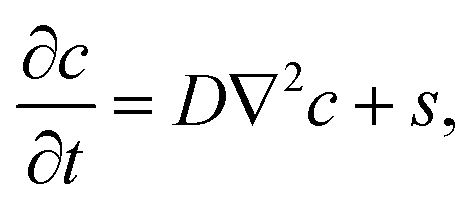 | (2) |
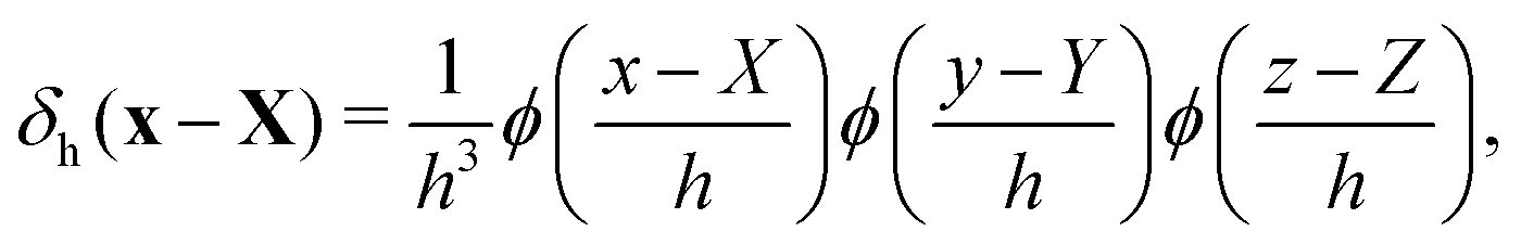
The boundaries of bubbles or droplets are discretized into a series of Lagrangian points. The Eulerian and Lagrangian sources are related to each other through a regularized delta function
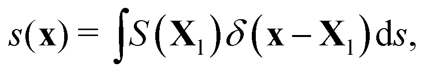 | (3) |
To enforce the prescribed concentration fields on the boundary, we define the Lagrangian concentration field. Using the regularized delta function again, this relation can be expressed as follows
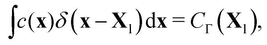 | (4) |
 | ||
| Fig. 2 Schematic sketch to illustrate the immersed boundary method: the diffusion equation is solved on the Eulerian Cartesian grid points x. The boundary Γ is discretized into a set of Lagrangian points X. The transfers of the concentration between the Eulerian and the Lagrangian grid (c → C) and the source term between the Lagrangian and Eulerian gird (S → s) are through the discrete regularized delta function δh, which covers the area A. | ||
In the discretized form, the diffusion equation for the kth step is solved through the following procedures. First, an intermediate “guessed” concentration field ![[c with combining macron]](https://www.rsc.org/images/entities/i_char_0063_0304.gif) is calculated from the Eulerian source term of the last step sk−1, with
is calculated from the Eulerian source term of the last step sk−1, with
| = ck−1 + Δt(D∇2ck−1 + sk−1). | (5) |
Next, we interpolate the intermediate concentration field from Eulerian () to Lagrangian (![[C with combining macron]](https://www.rsc.org/images/entities/i_char_0043_0304.gif) ) grid points through the discrete delta function δh, i.e.
) grid points through the discrete delta function δh, i.e.
 | (6) |
Apparently does not satisfy the boundary condition CΓ. In order to achieve CΓ, from eqn (5) the Lagrangian source term Sk for the current time step is derived as
 | (7) |
The next step is to spread the Lagrangian source term Sk to the Eulerian counterpart sk through the discrete delta function δh again, expressed as
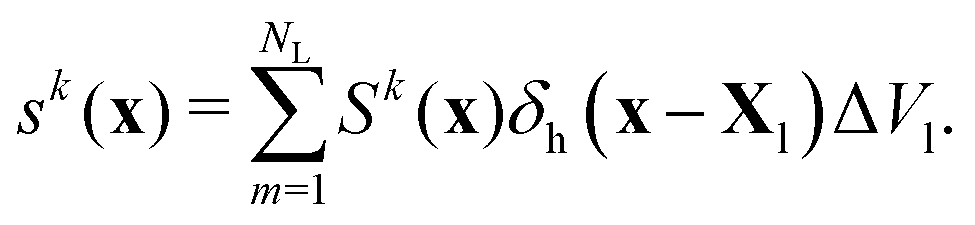 | (8) |
Finally, the concentration field with the Eulerian source term sk at kth step is solved from
 | (9) |
This ends one time step, after which the next time step is treated in the same way.
The regularized delta function used in the present study is defined as
 | (10) |
 | (11) |
3 Validation of the scheme for a single bulk bubble and a single surface bubble
We will now validate the scheme introduced in the previous section. We will assume two test cases: a spherical bubble in the bulk, whose growth or shrinkage behavior is analytically known since Epstein and Plesset29 (Section 3.1), and a surface nanobubble, which in the pinned case has a stable equilibrium contact angle given by eqn (1), and in the unpinned case either shrinks and then fully dissolves or grows and then finally detaches (Section 3.2). All the simulations that are shown below are performed with nitrogen bubble, for which the material parameters are D = 2 × 10⁻⁹ m2 s−1, ρg = 1.165 kg m−3, and cs = 0.017 kg m−3.3.1 The Epstein–Plesset bubble
In still liquid in an infinite domain, the mass loss or gain of a spherical bubble of radius R is given by the concentration gradient at its surface and the diffusion constant D,
 | (12) |
 | (13) |
Our numerical results of the relation between the bubble radius and time based on the scheme developed in the previous section are shown in Fig. 3 and compared with the analytical results (or the results from eqn (13)). Three cases are considered. In Fig. 3(a), the bubble surface concentration and gas density are kept constant, in Fig. 3(b), the density of the gas is kept constant and we use the Henry's law to calculate CΓ, and in Fig. 3(c), we vary the density of the bubble according to the ideal gas law and again the Henry's law is used to calculate CΓ. For all the cases, our simulations show excellent agreements with the predictions from eqn (13).
 | ||
| Fig. 3 Time evolution of the bubble radius R(t) for nitrogen gas bubble for three cases with c∞ = 0 and the same initial bubble radius 50 nm: (a) the bubble surface concentration and the gas density stay constant during the diffusion. (b) The gas density stays the same, however the surface concentration is given by Henry's law, where CΓ(R,t) = cs(1 + 2σ/R). (c) The gas density varies according to the ideal gas law and the surface concentration according to Henry's law as in (b). In the simulations here, the domain size is 0.5 μm × 0.5 μm × 0.5 μm. The resolution is of the computational domain is 201 × 201 × 201. Our numerical solutions agree very well with the exact Epstein–Plesset29 results. However, our results deviate from that of a quasistatic approximation ∂tc = 0. | ||
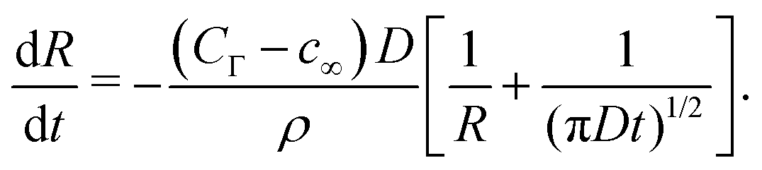
We now come to dissolving or growing surface bubbles and droplets (“sessile droplets”).1,30 For this axisymmetric case, Popov31 could exactly solve the quasi-static case ∂tc ≈ 0, i.e., the diffusion equation reduces to a Laplace question. For evaporating droplets as in the case of Popov, this in general is a very good approximation. Later the Popov model was also applied to surface nanobubbles.10 Then the gas concentration at the interface is again given by Henry's law which for surface bubbles takes the form CΓ(R,t) = cs[1 + 4σ![[thin space (1/6-em)]](https://www.rsc.org/images/entities/i_char_2009.gif) sin
sin![[thin space (1/6-em)]](https://www.rsc.org/images/entities/char_2009.gif) θ/(P0L)].
θ/(P0L)].
To check how important the time dependence of the concentration field is, we apply Popov's model for a dissolving bubble with a fixed contact angle of 90°, written as
 | (14) |
3.2 Stability of surface nanobubble & confirmation of the theory of Lohse & Zhang10
For nano-bubbles with pinned contact line, an ODE for the diffusive contact angle dynamics was derived in ref. 10, namely | (15) |
 | (16) |
Fig. 4(a) shows snapshots for the bubble evolution in the pinned case with L = 1 μm and ζ = 1, for which according to eqn (1) there should be a stable equilibrium,10 for fixed gas oversaturation ζ > 0. Indeed, the stable equilibrium angle θe = 20.6° is reached in the simulations. Fig. 4(b) shows the time evolution of the contact angle for two initial contact angles θi = 90° and θi = 5°. In both cases the contact angles saturate to the predicted θe = 20.6° when advancing time long enough. Further, we vary the oversaturation rate ζ from 0.4 to 1.6, in which the equilibrium contact angle θ would change, as shown in Fig. 4(c). Again our results are in perfect agreement with the prediction (eqn (1)).
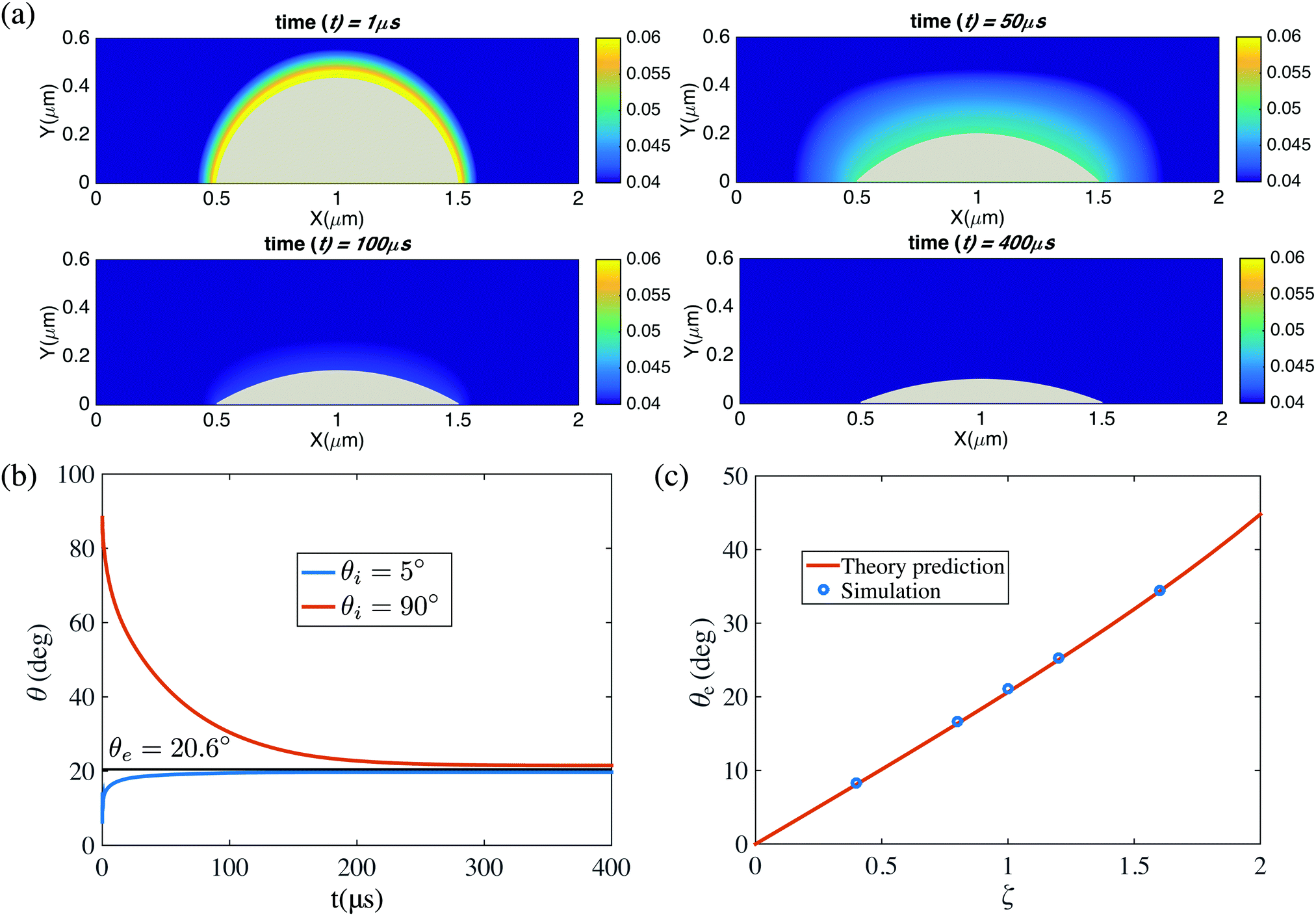 | ||
| Fig. 4 (a) Snapshots of the diffusive dynamics of a pinned surface nanobubbles growing towards its equilibrium state. The color code represents the gas concentration field. Here L = 1 μm and ζ = 1. (b) Time evolution θ(t) of the contact angle growing or shrinking towards its equilibrium value θe given by eqn (1). Two cases with different initial contact angles θi are shown. As above, L = 1 μm and ζ = 1. (c) Equilibrium contact angle θe for various gas concentrations ζ. The straight line is the prediction eqn (1), giving perfect agreement. Again, L = 1 μm. In the simulations here, the domain size is 6 μm × 3 μm × 6 μm. The resolution is of the computational domain is 301 × 151 × 301. The corresponding videos are shown as ESI.† | ||
In comparison, when a bubble is unpinned, even if with gas oversaturation, the bubble can not be stable because of the Laplace pressure, In Fig. 5, we show the time evolution of a bubble in a constant contact mode with fixed contact angle θ = 90°. The oversaturation ζ = 1 but still the bubble dissolves very quickly.
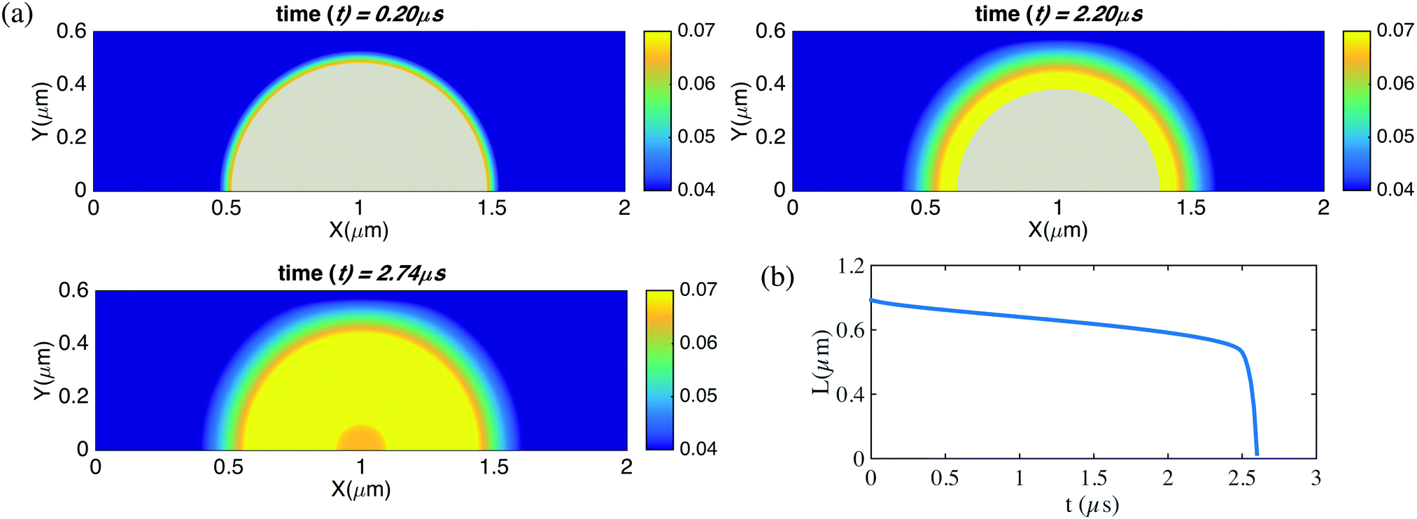 | ||
| Fig. 5 Time evolution for the contact diameter L(t) for an unpinned surface nanobubble with pre-described constant contact angle θ = 90° and gas oversaturation ζ = 1. The bubble dissolves within 3 microseconds. In the simulations here, the domain size is 6 μm × 3 μm × 6 μm. The resolution is of the computational domain is 301 × 151 × 301. The corresponding videos are shown as ESI.† | ||
We take the opportunity here to discuss the assumptions that lead to eqn (15). Henry's law is used when deriving eqn (15), however the gas density is assumed constant and the process is assumed quasi-steady. Let's first focus on the quasi-steady assumption. The typical diffusion time scale is td = R2/D, while the evaporation/dissolution time scale te = tdρ/(cs − c∞). For a water droplet evaporation, te/td is of the order of 105, thus eqn (15) is a rather good approximation32 without considering the time dependent term of the diffusion equation. However, for a gas bubble, te/td is of the order of 102, thus the quasi-steady condition can not be valid anymore, as also shown in Fig. 3(b). Also the gas density might vary because of the Laplace pressure. However, it is easy to see from eqn (15) and (3) that these considerations are only relevant for the time scale of the evolution towards the equilibrium contact angle θe, not for the value of θe itself.
4 Ostwald ripening process of two bubbles: unpinned vs. pinned case
We now move to the case of two bubbles, for which the general argument for nanobubble stability is not available anymore. One exception is the case where two bubbles are far away from each other. For this case Dollet and Lohse18 theoretically show that pinning also suppresses the Ostwald ripening process between neighbouring surface nanobubbles. But this case is not given in most experiments, in which the nanobubbles sit very close to each other and nonetheless can remain stable for very long time.7 In this paper we will now show with numerical simulations that this stabilization of a pair of surface bubbles through pinning is indeed not limited to bubbles far away from each other but also holds for bubbles that are close.
Fig. 6 shows two cases, the first one for two surface bubbles with same fixed contact diameter L1 = L2 = 1 μm and the second one with different contact diameters L1 = 1 μm, L2 = 0.7 μm. In both cases we set the oversaturation to ζ = 2 and have pinned contact lines. It can be seen that with pinning and gas oversaturation, indeed the two bubbles case are eventually stable, even if the distance between them are very close. Specifically, for the case with same contact diameter, both have the stable equilibrium contact angle θe = 40.7° given by eqn (1). For the case with different contact diameters, one bubble has the stable equilibrium contact angle θe = 40.7° and the other one θe = 29.6°, however, the radii of curvature L/cosθe for the two bubbles are the same, as it should be according to the theory of Lohse and Zhang.10
 | ||
| Fig. 6 (a and c) Snapshots of the time evolution of two pinned neighbouring bubbles and the surrounding gas concentration field. The oversaturation is ζ = 2. For (a), the contact diameters are L1 = L2 = 1 μm. The initial contact angle for the left bubble is 90° and for the right bubble is 15°. For (c), the contact diameters are L1 = 1 μm and L2 = 0.7 μm. The initial contact angle for the left bubble is 15° and for the right bubble is 90°. The pinning stabilizes the two bubbles against Ostwald ripening and the contact angles of both bubbles converge to θe, as given by eqn (1). (b and d) Contact angles of the two bubbles as function of time for cases (a) and (c). In (d) (case (c), and in (b) (case (a)) of course anyhow), the resulting radii of curvature L/cosθe are identical. In the simulations here, the domain size is 6 μm × 3 μm × 6 μm. The resolution is of the computational domain is 301 × 151 × 301. The corresponding videos are shown as ESI.† | ||
For the bubbles with unpinned contact line, Ostwald ripening indeed diffusively destabilizes the two neighboring bubble. In Fig. 7 we show two bubbles with the same condition as in Fig. 6(a and b), but now unpinned and with constant contact angles. It can be seen that the two bubbles diffusively interact with each other, leading to Ostwald ripening: therefore one bubbles dissolves and the other one grows.
 | ||
| Fig. 7 (a) Snapshots of the time evolution of two unpinned neighbouring bubbles and the surrounding gas concentration field. The parameters are the same as in the case of Fig. 6(a). In the absence of pinning the pair of bubbles undergoes Ostwald ripening, i.e., one bubble grows and the other ones dissolves. (b) Contact diameters of the two bubbles as function of time. The red curve shows the contact diameter of the growing right bubble, and the blue one that of the shrinking left bubble, which is fully dissolved in the end. In the simulations here, the domain size is 6 μm × 3 μm × 6 μm. The resolution is of the computational domain is 301 × 151 × 301. The corresponding videos are shown as ESI.† | ||
5 Diffusive coarsening process for an one-dimensional array of bubbles
Finally, we look at the coarsening process for an one-dimensional array of bubbles. In Fig. 8(a), we show an array of 5 bubbles. The bubbles all have a constant contact angle of 90°. Initially, bubble 1 and bubble 5 have contact diameters of 1.44 μm, bubble 2 and bubble 4 have contact diameters of 1.45 μm, and bubble 3 has a contact diameter of 1.46 μm. Because of the Henry's law, smaller bubble will have a higher surface concentration while bigger one lower. Thus a concentration gradient between different bubbles is formed and the coarsening process starts. Interestingly, it is not bubble 1 and 5, which have the lowest surface concentration that are eaten by other bubbles, but bubble 2 and 4, which are in between. We see after the disappearance of bubbles 2 and 4, all other three bubbles become bigger, however with time advancing, the even bigger bubble 3 finally eats all the other bubbles and the coarsening process ends. Similar effects can be found for more bubbles, in Fig. 8(c), we show an array of 13 bubbles. In this case, bubble contact diameters are from 1.44 μm to 1.5 μm, with an increase of 0.01 μm for each from bubble 1 to bubble 7. Then from bubble 7 to bubble 13, the contact diameter decreases 0.01 μm for each. Analogous to the coarsening process of shaken compartimentalized granular matter of ref. 21, here for nanobubbles we find that with time passing by and thus the distance between the bubbles growing, the coarsening process also slows down, as shown in Fig. 8(b and d). | ||
| Fig. 8 (a) Coarsening processes for five neighboring bubbles in a row. The oversaturation is ζ = 1. The five bubbles have slightly different initial contact diameters, i.e. bubble 1 and bubble 5 have 1.44 μm, bubble 2 and bubble 4 have 1.45 μm, and bubble 3 has 1.46 μm. The bubbles are in the constant contact angle mode. (b) The time evolution of the contact diameters for the 5 bubbles. (c and d) The same as (a and b), but now for thirteen initial bubbles. Bubble contact diameters are from 1.44 μm to 1.5 μm, with an increase of 0.01 μm for each from bubble 1 to bubble 7. Then from bubble 7 to bubble 13, the contact diameter decreases 0.01 μm for each. Here we can use the two-dimensional axis-symmetric simulations because the contact angle is 90°. For (a), the domain size is 8.8 μm × 3 μm. The resolution is 881 × 301. For (c), the domain size is 24 μm × 4 μm. The resolution is 2401 × 401. The corresponding videos are shown as ESI.† | ||
6 Conclusions and outlook
Simulations of finite difference combined with the immersed boundary methods were performed to study the stability and instability of nanobubbles. Four difference configurations were considered, a bulk bubble, a surface bubble, two close surface bubbles, and an array of surface bubbles. For bulk bubbles, the simulated time evolution of the bubble radius shows excellent agreements with Epstein & Plesset's analytical results,29 validating our scheme and code. For single surface nanobubbles, our simulations confirm that pinning and oversaturation can indeed stabilize the surface nanobubble, and the equilibrium contact angle perfectly agrees with the analytical result eqn (1) of Lohse and Zhang.10 Thus a consistent picture between our prior theoretical calculations and the present numerical simulations has emerged. For two neighbouring nanobubbles, we find that pinning and oversaturation can stabilize the nanobubble pair against Ostwald ripening, even when the bubbles are very close to each other. Finally, we show the coarsening process for a row of nanobubbles. The coarsening slows down with advancing time and increasing nanobubble distance, similar to the coarsening process as seen in shaken compartimentalized granular matter.21We note that though here we give the results only for surface nanobubbles, corresponding results should also hold for surface nanodroplets. We also note that for the parameters of this study here, the dominant coarsening process is Ostwald ripening, i.e., mass exchange by diffusion, but for other parameters (e.g. larger oversaturation) the dominant process can also be bubble coalescence. To map out the parameter space when Ostwald ripening will be dominant and when bubble coalescence will be the subject of future work. Correspondingly, in future work we also want to extend this study from surface bubbles or surface droplets in a row to those in a two-dimensional array as experimentally done in e.g.ref. 17 and 33 or to randomly distributed surface bubbles or droplets as in ref. 22. Future work can also address how heterogeneities on the gas-water interfaces through e.g. local surfactant accumulation can affect the overall dynamics of the bubble ensemble.
Finally, we caution the reader: our results are based on continuum theory and hydrodynamic equations. However, at very short length scales the continuum approximation will break down. In very recent molecular dynamics (MD) simulations, Maheshwari et al.34 have revealed that in certain cases (very strong attraction between the dissolved gas molecules and the surface) surface nanobubbles very close to each other can communicate through a “new channel”, namely diffusion of gas from one surface bubble to the other along the surface, and not through the bulk. If this is the case, some sort of ripening process of neighboring surface bubbles may be possible in spite of hydrodynamic stability against Ostwald ripening.
Conflicts of interest
There are no conflicts to declare.Acknowledgements
We acknowledge support from Foundation for Fundamental Research on Matter (FOM), which is part of the Netherlands Organisation for Scientific Research (NWO), the Netherlands Center for Multiscale Catalytic Energy Conversion (MCEC), an NWO Gravitation programme funded by the Ministry of Education, Culture and Science of the government of the Netherlands, and an ERC-Advanced Grant. X. H. Z. also acknowledges support from the Australian Research Council (FT120100473). This work was carried out on the Dutch national e-infrastructure with support of SURF Cooperative. We also acknowledge PRACE for awarding us access to Marconi at CINECA, Italy under PRACE Project No. 2016143351 and the DECI resource Fionn at ICHEC, Ireland with support from the PRACE aisbl under project number 14DECI005. Open Access funding provided by the Max Planck Society.References
- D. Lohse and X. Zhang, Rev. Mod. Phys., 2015, 87, 981–1035 CrossRef CAS.
- J. L. Parker, P. M. Claesson and P. Attard, J. Phys. Chem., 1994, 98, 8468–8480 CrossRef CAS.
- N. Ishida, T. Inoue, M. Miyahara and K. Higashitani, Langmuir, 2000, 16, 6377–6380 CrossRef CAS.
- J. W. G. Tyrrell and P. Attard, Phys. Rev. Lett., 2001, 87, 176104 CrossRef CAS PubMed.
- S.-T. Lou, Z.-Q. Ouyang, Y. Zhang, X.-J. Li, J. Hu, M.-Q. Li and F.-J. Yang, J. Vac. Sci. Technol., B, 2000, 18, 2573–2575 CAS.
- V. S. J. Craig, Soft Matter, 2011, 7, 40–48 RSC.
- X. Zhang, D. Y. C. Chan, D. Wang and N. Maeda, Langmuir, 2013, 29, 1017–1023 CrossRef CAS PubMed.
- Y. Liu and X. Zhang, J. Chem. Phys., 2013, 138, 014706 CrossRef PubMed.
- Y. Liu and X. Zhang, J. Chem. Phys., 2014, 141, 134702 CrossRef PubMed.
- D. Lohse and X. Zhang, Phys. Rev. E: Stat., Nonlinear, Soft Matter Phys., 2015, 91, 031003(R) CrossRef PubMed.
- S. Maheshwari, M. van der Hoef, X. Zhang and D. Lohse, Langmuir, 2016, 32, 11116–11122 CrossRef CAS PubMed.
- E. A. Fadlun, R. Verzicco, P. Orlandi and J. Mohd-Yusof, J. Comput. Phys., 2000, 161, 35–60 CrossRef.
- C. S. Peskin, Acta Numer., 2002, 11, 479–517 CrossRef.
- R. Mittal and G. Iaccarino, Annu. Rev. Fluid Mech., 2005, 37, 239–261 CrossRef.
- B. Song, W. Walczyk and H. Schönherr, Langmuir, 2011, 27, 8223–8232 CrossRef CAS PubMed.
- S. Peng, T. L. Mega and X. Zhang, Langmuir, 2016, 32, 11265–11272 CrossRef CAS PubMed.
- S. R. German, X. Wu, H. An, V. S. J. Craig, T. L. Mega and X. Zhang, ACS Nano, 2014, 8, 6193–6201 CrossRef CAS PubMed.
- B. Dollet and D. Lohse, Langmuir, 2016, 32, 11335–11339 CrossRef CAS PubMed.
- P. W. Voorhees, J. Stat. Phys., 1985, 38, 231–252 CrossRef.
- S. Peng, D. Lohse and X. Zhang, ACS Nano, 2015, 9, 11916–11923 CrossRef CAS PubMed.
- D. van der Meer, K. van der Weele and D. Lohse, J. Stat. Mech.: Theory Exp., 2004, 2004, P04004 Search PubMed.
- X. Zhang, Z. Lu, H. Tan, L. Bao, Y. He, C. Sun and D. Lohse, Proc. Natl. Acad. Sci. U. S. A., 2015, 112, 9253–9257 CrossRef CAS PubMed.
- H. Tan, C. Diddens, P. Lv, J. G. M. Kuerten, X. Zhang and D. Lohse, Proc. Natl. Acad. Sci. U. S. A., 2016, 113, 8642–8647 CrossRef CAS PubMed.
- D. Beysens and C. M. Knobler, Phys. Rev. Lett., 1986, 57, 1433–1436 CrossRef PubMed.
- F. Family and P. Meakin, Phys. Rev. A: At., Mol., Opt. Phys., 1989, 40, 3836–3854 CrossRef CAS.
- J. W. Rose, Proc. Inst. Mech. Eng., Part A, 2002, 216, 115–128 CrossRef CAS.
- R. N. Leach, F. Stevens, S. C. Langford and J. T. Dickinson, Langmuir, 2006, 22, 8864–8872 CrossRef CAS PubMed.
- L. Stricker and J. Vollmer, Phys. Rev. E: Stat., Nonlinear, Soft Matter Phys., 2015, 92, 042406 CrossRef CAS PubMed.
- P. S. Epstein and M. S. Plesset, J. Chem. Phys., 1950, 18, 1505–1509 CrossRef CAS.
- A. M. Cazabat and G. Guéna, Soft Matter, 2010, 6, 2591–2612 RSC.
- Y. O. Popov, Phys. Rev. E: Stat., Nonlinear, Soft Matter Phys., 2005, 71, 036313 CrossRef PubMed.
- H. Gelderblom, A. G. Marin, H. Nair, A. van Houselt, L. Lefferts, J. H. Snoeijer and D. Lohse, Phys. Rev. E: Stat., Nonlinear, Soft Matter Phys., 2011, 83, 026306 CrossRef PubMed.
- L. Bao, Z. Werbiuk, D. Lohse and Z. Zhang, J. Phys. Chem. Lett., 2016, 7, 1055–1059 CrossRef CAS PubMed.
- S. Maheshwari, M. van der Hoef, J. Rodriguez-Rodriguez and D. Lohse, ACS Nano, 2018 DOI:10.1021/acsnano.7b08614.
Footnote |
| † Electronic supplementary information (ESI) available. See DOI: 10.1039/c7sm02523h |
| This journal is © The Royal Society of Chemistry 2018 |