
Will the competitive future of solid state Li metal batteries rely on a ceramic or a composite electrolyte?†
Antonio
Gutiérrez-Pardo
a,
Andrea I.
Pitillas Martinez
a,
Laida
Otaegui
a,
Meike
Schneider
b,
Andreas
Roters
b,
Anna
Llordés
 ac,
Frédéric
Aguesse
*a and
Lucienne
Buannic
*a
ac,
Frédéric
Aguesse
*a and
Lucienne
Buannic
*a
aCIC Energigune, Parque Tecnológico de Álava, Albert Einstein 48, 01510 Miñano, Spain. E-mail: faguesse@cicenergigune.com; l.buannic@gmail.com
bSchott AG, Hattenbergstraße 10, 55122 Mainz, Germany
cIKERBASQUE, The Basque Foundation for Science, Maria Diaz de Haro 3, 48013 Bilbao, Spain
First published on 24th August 2018
Abstract
The industrial development of Li metal solid state batteries will be boosted not only by providing highly Li+ conductive electrolyte materials, but also by demonstrating their technical viability in the actual device. For the first time, the electrochemical performances of two different electrolytes, a pure Li7La3Zr2O12 ceramic and a polymer–ceramic composite, are compared in a solid state battery with a Li metal anode and a LiFePO4 cathode. No liquid or gel additive was added to improve the interfacial contacts. The technological viability of these two systems was assessed under realistic cycling conditions with a competitive cathode loading of 1 mA h cm−2. Here, we show promising performances for both electrolytes at 70 °C under slow cycling rates; however, the composite stands out under fast cycling rates due to enhanced interfacial contacts. The energy density of the two systems is compared to the electric vehicle industry targets providing clear specifications for future system development.
Introduction
Li metal anodes had been dismissed very early on in the development of secondary lithium ion batteries (LIB) due to the possibility of short-circuiting triggered by the formation of Li dendrites in the liquid electrolyte upon cycling.1 However, Li metal anodes have recently regained interest, in part due to the successful development of solid electrolytes which can potentially prevent the formation of such dendrites.2 In addition, the combination of a thin solid electrolyte and a Li metal anode is one of the few ways to increase the energy density of the current LIB technology.3The solid electrolyte of a Li metal solid state battery (SSB) can be selected amongst three different families: polymer, inorganic, and polymer–inorganic composites. Each family provides advantages and inconveniences.4 For example, solid polymer electrolytes offer ease of processing but low ionic conductivities at room temperature. Inorganic sulfidic glasses are soft and the fastest Li+ conductors by far, but are generally unstable in air, in contact with Li metal, and with most cathode materials. In turn, some oxides, and in particular the Li7La3Zr2O12 (LLZO) garnet, display a high ionic conductivity combined with a wide chemical and electrochemical stability window.5–8 These properties make the LLZO garnet a very strong candidate for Li metal solid state battery applications; however, it remains challenging to prepare a thin layer of the material providing bulk performances. The combination of a polymer matrix with an inorganic electrolyte, i.e. a composite, can facilitate the processing of the oxide, simplifying its application in a solid state battery; but so far the ionic conductivity of such composite remains well below the one of the LLZO garnet9–11 and could be limiting the SSB performances.
When implementing a ceramic such as the LLZO garnet in a Li metal SSB, the rigid solid–solid interaction at the cathode–electrolyte interface is kinetically limiting and the use of an interfacial liquid phase has proven necessary to operate the cell for more than a few cycles.12,13 One way to circumvent this limiting solid–solid interface is to add a fraction of solid electrolyte in the cathode layer, which is typically referred to as catholyte. The use a soft catholyte integrated into the cathode layer14,15 or inserted in between the electrolyte and the electrodes16 leads to good contact with the rigid ceramic electrolyte and facilitates ionic transport across the cathode–electrolyte interface as well as throughout the cathode itself.
Aside from the LLZO garnet, composite electrolytes are great electrolyte candidates for SSB application as they gather the softness of the polymer matrix with an increased electrochemical stability window in comparison to a polymer electrolyte.10,17 In the last two years, a large amount of work has been dedicated to characterizing such composite electrolytes; however, there are few studies assessing their integration into Li metal solid state batteries.17–20 In addition, those studies include either a low cathode loading (≈0.3 mA h cm−2) and/or a large fraction of catholyte (>50 vol%), which would both be a penalty in terms of energy density, leading to cell characteristics far from competitive. It is therefore difficult to evaluate their potential future in such application.
Here, our goal is to compare the suitability of two major contenders as electrolyte materials for Li metal SSB: the LLZO garnet and its PEO-based composite counterpart. The assembled Li metal solid state cells rely on a polymer–ceramic composite catholyte to guarantee good contact between the electrolyte layer and the cathode as well as to provide an electrochemically stable ionic conductivity network within the cathode. The two electrolytes are first briefly characterized to assess their behavior as solid electrolyte. Their C-rate and cycling performances in Li metal solid state batteries are then compared with a LiFePO4 cathode under an unprecedented active material loading of 1 mA h cm−2. In order to put into perspective the implementation of the two selected candidates in commercial solid state batteries, the energy density of each system is evaluated and guidelines are provided with respect to electrolyte thickness and active material loading requirements to promote their competitive future.
Experimental details
Ceramic pellet preparation
To prepare the ceramic electrolyte, we used a cubic Li7La3Zr2O12 (LLZO) powder prepared by Schott AG. Ceramic green bodies were obtained from uniaxial pressing at 0.75 ton in a 6 mm diameter pellet die. The green bodies were then embedded into their mother powder and placed on alumina boats for sintering at 1200 °C under dry 99.99% O2 atmosphere for 6 hours. The sintered pellets were progressively abraded in an Ar filled glove box (H2O and O2 contents ≤ 0.1 ppm) using SiC polishing papers to remove any surface Li2CO3 or LiOH and to obtain finely polished surfaces. For reproducibility, all the ceramic pellets were thinned down to 1 mm before cell assembly. The relative density of each pellet was geometrically measured after polishing and compared to the theoretical density of the LLZO powder provided by Schott (4.8 g cm−3).Composite membrane preparation
Polymer–ceramic composite membranes consisting of 90 vol% of polyethylene oxide (PEO, Sigma Aldrich, Mv 5 M) and lithium bis(trifluoromethane)sulfonimide salt (LiTFSI, Sigma Aldrich, 99.95%) and 10 vol% of cubic LLZO (Schott AG), were prepared in an Ar filled glove box. The EO![[thin space (1/6-em)]](https://www.rsc.org/images/entities/char_2009.gif) :Li molar ratio was fixed to 20:1. Based on the density of each material, this composition corresponds to a membrane with 72 wt% of PEO-LiTFSI and 28 wt% of LLZO. To minimize the water content, PEO was dried in a vacuum oven (Büchi) at 50 °C for 12 h before being transferred to the glove box. LiTFSI and LLZO powders were received and stored under argon atmosphere. PEO, LiTFSI, and LLZO were first mixed in anhydrous acetonitrile (ACN, Sigma Aldrich, 99.8%) and stirred for 24 h. The slurry was then ball milled (Micro Pulverisette 7 premium, Fritsch) before being tape casted under argon atmosphere. The casted membrane was dried at 50 °C for 12 h under dynamic vacuum in an oven connected to the glove box.
:Li molar ratio was fixed to 20:1. Based on the density of each material, this composition corresponds to a membrane with 72 wt% of PEO-LiTFSI and 28 wt% of LLZO. To minimize the water content, PEO was dried in a vacuum oven (Büchi) at 50 °C for 12 h before being transferred to the glove box. LiTFSI and LLZO powders were received and stored under argon atmosphere. PEO, LiTFSI, and LLZO were first mixed in anhydrous acetonitrile (ACN, Sigma Aldrich, 99.8%) and stirred for 24 h. The slurry was then ball milled (Micro Pulverisette 7 premium, Fritsch) before being tape casted under argon atmosphere. The casted membrane was dried at 50 °C for 12 h under dynamic vacuum in an oven connected to the glove box.
Cathode preparation
The cathode content was determined by fixing the LiFePO4:C wt. ratio to 93:7 and including 50 vol% of catholyte, the latter having the same composition as the composite membrane. This corresponds to a cathode composition of 44:50:6 vol% or 63:32:5 wt% of LiFePO4:catholyte:C, taking into consideration densities of 3.51, 1.56, and 1.88 g cm−3 for each component, respectively. A commercially available 6% carbon coated LiFePO4 (LFP) of 800 nm primary particle size (Advance Lithium Electrochemistry Co) and C (C65, TIMCAL) were dried at 80 °C in a vacuum oven (Büchi) for 12 h before being transferred to an Ar filled glove box. The catholyte mixture was first prepared by dissolving stoichiometric ratios of PEO, LiTFSI, and LLZO in ACN. The solution was stirred overnight before being transferred to the ball milling jar. LFP and C were mixed separately in an agate mortar with 2 mL of N-methyl-2-pyrrolidone (NMP, Sigma Aldrich, 99.5%) and transferred to the ball milling jar on top of the catholyte slurry. The cathode mixture was then ball milled (Micro Pulverisette 7 premium, Fritsch) and tape casted onto aluminum foil. The laminates were dried in an oven connected to the glove box at 60 °C for 12 h under dynamic vacuum. The loading of the cathode ranged between 0.8 and 1.2 mA h cm−2 considering 170 mA h g−1 as the cathode theoretical capacity.
SEM
The microstructure of the electrolytes and the cathode laminates was analyzed by Scanning Electron Microscopy (SEM) using a FEI Quanta 200 FEG operated at a voltage of 20 or 30 kV, using either secondary (SE) or backscattered electron (BSE) detectors. Elemental composition of the cathode laminate was acquired using Energy Dispersive X-ray Spectroscopy (EDS). For cross section imaging, the pellet was gently broken in an Ar filled glove box and quickly transferred to the SEM chamber to minimize air exposure, while the membrane was first frozen using liquid nitrogen and then broken to obtain a sharp cut.Ionic conductivity measurements
For the ceramic electrolyte, a symmetric cell was prepared using two Li metal disks as electrodes pressed on both sides of the ceramic pellet applying a uniaxial pressure of 0.05 ton, which leads to a final Li diameter of 4.3 mm. For the composite, a dried membrane was placed in between 2 stainless steel disks of 16 mm diameter. The ionic conductivity of each system was measured in CR2032 coin cells mounted in an Ar filled glove box. The cell containing the composite electrolyte was heated to 80 °C for 24 h prior to the measurements to ensure stabilization and good contact between the membrane and the electrodes. Electrochemical impedance spectroscopy measurements (EIS) were carried out using a Solartron 1260A Impedance Analyzer with frequencies ranging between 32 MHz and 1 Hz and 50 mV excitation amplitude. The measurements were performed every 10 °C from 70 to 0 °C and from 80 to 10 °C for the ceramic and the composite electrolyte, respectively, following an equilibration time of 50 min at each temperature. A 24 h thermal treatment at 70 °C is performed on the SSBs prior cycling; therefore, only the ionic conductivities on cooling are reported to be consistent with our SSB preparation procedure. The obtained Nyquist plots were fitted using different models to obtain the electrolyte resistance for the whole range of temperatures (Fig. S1, ESI†). The ionic conductivity was determined using the following equation: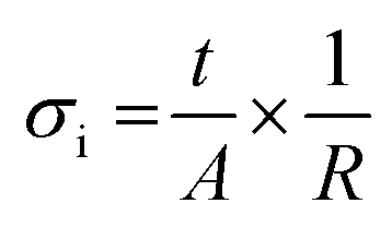 | (1) |
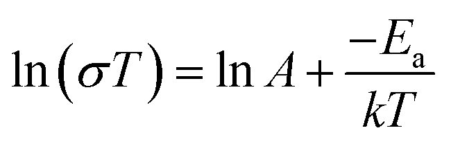
The activation energy of each electrolyte was calculated according to the following equation:
 | (2) |
Stripping plating experiments
Li stripping plating experiments were carried out on symmetric cells containing either the ceramic pellet (diameter 5.6 mm) or the composite membrane (diameter 16 mm) and two Li electrodes (diameter of 4.3 and 14 mm for the pellet and the membrane, respectively), assembled in an Ar filled glove box. Prior to testing, the cells were conditioned at 70 °C for 24 h to ensure good contact at the interface between the electrolyte and the Li electrodes. Galvanostatic cycling was performed at various current densities for 5 cycles with steps of 2 h using a Maccor Series 4000 potentiostat. The current densities were calculated to match the values of targeted C-rates (C/100, C/50, C/20, C/10, C/5, C/2, and 1C) assuming an areal capacity of 1 mA h cm−2.Electrochemical characterization
To evaluate the electrochemical performance of the two electrolytes in Li metal SSB, CR2032 coin cells were assembled in an Ar filled glove box. A cathode, electrolyte, and Li metal disk with respective diameters of 4.0, 5.6, and 4.3 mm for the ceramic electrolyte cell and 13, 16, and 14 mm for the composite electrolyte cell were used. The cells were conditioned at 70 °C for 24 h to ensure good interfacial contact. Rate capability was assessed by performing 5 cycles at C/20, C/10, C/5, C/2, and 1C using a Maccor Series 4000 potentiostat. The steps were limited in time, with a time value slightly larger than the selected C rate – for example 10.5 h at C/10 – to prevent irreversible degradation of the electrolyte/catholyte and subsequent cell failure in case the step cut off voltage could not be reached. Additional cycles were done at C/10 to check the ability of the system to recover its initial performance after fast cycling. Tests were also run starting directly at C/10 to evaluate cycle life. The upper cut-off voltage of the SSB based on the ceramic electrolyte was set to a higher value than that of the composite electrolyte, with 4.0 and 3.7 V, respectively, due to the larger polarization occurring with the former. The lower cut-off voltage was fixed to 2.7 V for all cells.Energy density calculations
The specific and volumetric energy densities for each of the two systems were calculated. Monolayer cells composed of a Li metal anode, one of the two electrolytes evaluated in this manuscript (density = 1.56 and 4.80 g cm−3 for the composite and the ceramic compound, respectively), and a LFP cathode with the same formulation as the experimental one coated on top of a 10 μm thick Al current collector were considered for the calculations. The amount of Li metal anode was fixed to 3 times the capacity of the cathode (i.e. 3 × 1 mA h cm−2, considering our active material loading) in order to have sufficient lithium excess.1 A theoretical capacity of 170 mA h g−1 was assumed for the estimation of the cathode active material mass and the cell voltage was set to 3.45 V. All the components were considered porosity-free and the cell casing was not taken into consideration.Results and discussion
Microstructure and composition
XRD characterization of the LLZO powder confirms the presence of the cubic LLZO phase before and after sintering (Fig. S2, ESI†). Geometrical measurements of the sintered pellets reveal a high density, ranging between 95 and 99%, which indicates excellent sinterability of the LLZO powder. In agreement, only a few pores can be detected in the pellet cross section, while the presence of large grains (>50 μm) is evident (Fig. 1a). The composite membrane shows no sign of porosity and a homogenous dispersion of the ceramic particles (white areas in the SEM images) on the surface (Fig. 1b) and along its thickness (Fig. 1c), estimated to be about 40 μm. The cathode laminate shows some degree of porosity (Fig. 1d). Adjustment of the amount of solvent used in the slurry preparation could minimize the amount of porosity after drying, but the optimization of the cathode processing is beyond the scope of this manuscript. The SEM image obtained using backscattered electrons highlights a homogenous composition of the laminate (Fig. 1e) with experimental LFP:LLZO:LiTFSI ratios (82.2:10.4:7.4 wt%) close to the theoretical values (81.2:11.6:7.2 wt%) (Fig. 1f), based on the signals acquired for Fe, La, and S by EDS.
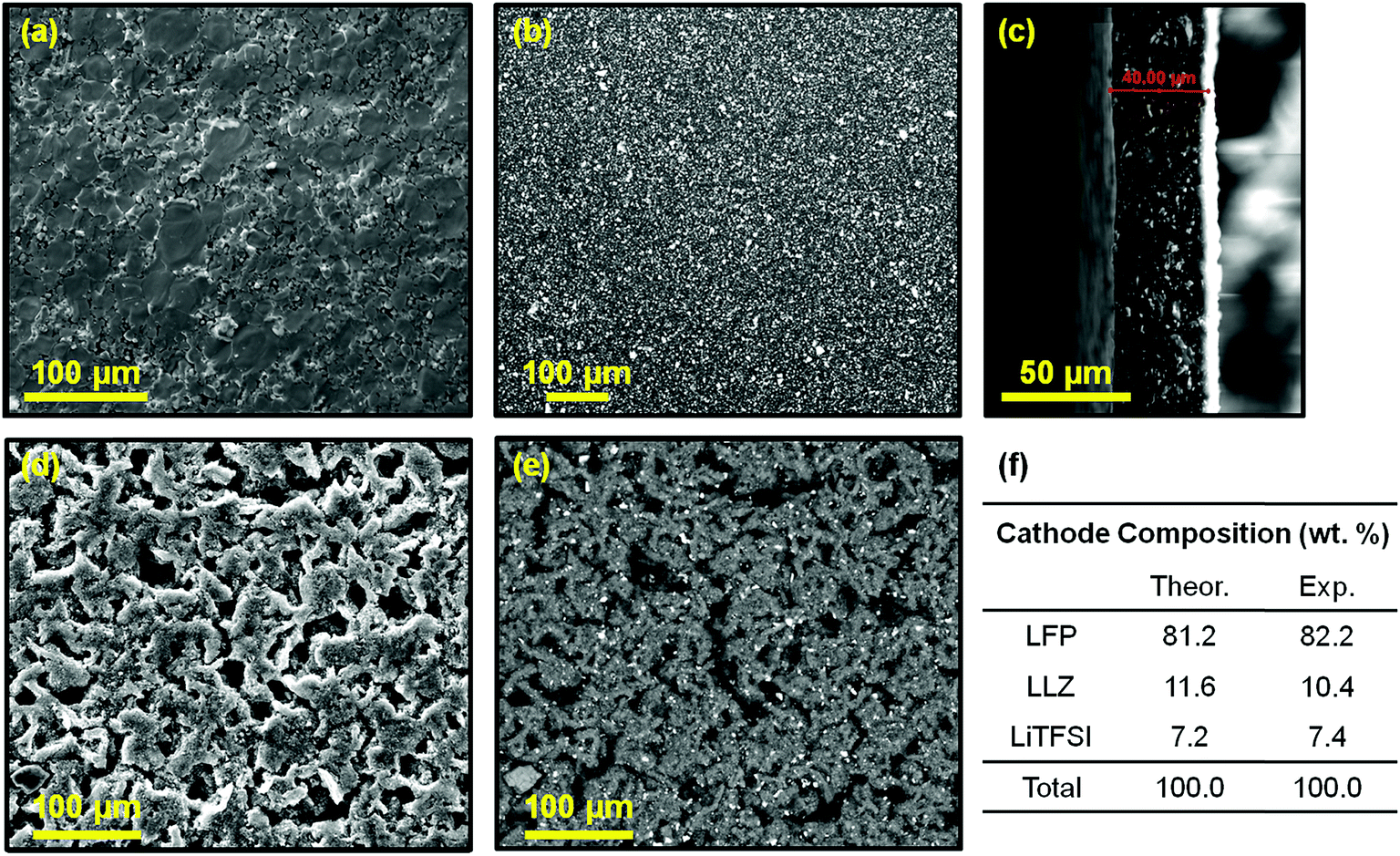 | ||
| Fig. 1 Microstructure of (a) the cross section of the LLZO pellet, (b) the surface and (c) cross section of the composite membrane, and (d and e) the cathode laminate. (f) Theoretical and experimental cathode composition obtained by EDS. (a, c, and d) and (b and e) images were obtained using a secondary and backscattered electron detectors, respectively. | ||
Ionic mobility
Fig. 2a shows the Nyquist plots obtained for the pure ceramic and the composite membrane at 25 °C. For the ceramic, two semicircles are observed. The one at high frequencies corresponds to the total Li+ conductivity (bulk and grain boundary) of the pellet while the one at low frequencies represents the interfacial resistance between the pellet and the Li electrodes. For the composite membrane, a semicircle followed by a tail can be observed at low temperatures (<40 °C), which are representative of the membrane resistance and the stainless steel blocking electrodes, respectively. At higher temperatures (>40 °C), the semicircle cannot be resolved due to equipment limitations and only the blocking electrode tail is observed (Fig. S1, ESI†). The ionic conductivity of each sample was extracted from the Nyquist plots (see experimental details and ESI†). At 25 °C, the ionic conductivity of the ceramic is two orders of magnitude higher than that of the composite, with 3.9 × 10⁻⁴vs. 2.6 × 10⁻⁶ S cm−1, respectively. This difference decreases to one order of magnitude when the temperature is above 50 °C. Ionic conductivities of 2.5 × 10⁻³ S cm−1 and 1.7 × 10⁻⁴ S cm−1 were obtained at 70 °C for the ceramic and the composite, respectively. Those ionic conductivity values are similar to the ones previously reported.11,21–23 | ||
| Fig. 2 Electrochemical characterization of the two electrolytes: (a) Nyquist plots at 25 °C, (b) Arrhenius plots of ionic conductivity, and stripping plating experiments performed at 70 °C with 2 h steps for (c) the ceramic and (d) the composite electrolyte. | ||
The Arrhenius plot of the ceramic shows a linear trend between 70 and 0 °C, with an activation energy of 0.44 eV. In comparison, two linear regions can be observed for the composite membrane, the first one between 80 and 55 °C and the second one between 50 and 10 °C. The change in the slope observed at about 53 °C, corresponds to the melting temperature of the polymer, as confirmed by DSC results (Fig. S3, ESI†). Below the melting temperature, the membrane has an activation energy of 1.10 eV indicating difficult ion hopping. However, above its melting temperature, the activation energy drops to 0.35 eV, falling below the one of the ceramic electrolyte, indicating lower energy barriers between Li+ sites in the melted composite membrane compared to the pure ceramic. Above 50 °C, the ionic mobility of both electrolytes seems sufficient to operate a SSB (ionic conductivity > 10−4 S cm−1). At room temperature, the properties of the ceramic are very promising; however interfacial resistances between the electrolyte and the electrodes and between the electrode components will also play a crucial role. To ensure sufficiently fast ionic mobility in both electrolytes and in the cathode (through the composite based catholyte) during SSB testing, the operating temperature was set to 70 °C, i.e. above the melting temperature of the composite membrane.
Stripping plating in symmetric cells
Stripping plating experiments were performed to evaluate the stability of the interface between the electrolyte and Li metal during cycling at 70 °C. The ceramic electrolyte is able to withstand up to 100 μA cm−2 (Fig. 2c). At 200 μA cm−2, the cell polarization suddenly decreases and is accompanied by a low resistance behavior in the Nyquist impedance plot (Fig. S4, ESI†). Prior studies have demonstrated similar critical current densities with LLZO pellets stable up to 100 μA cm−2 at 50 °C for 2 h (with an interfacial Au coating),24 100 μA cm−2 at 60 °C for 2 h,25 200 μA cm−2 at 70 °C for 30 min (after 10 formation cycles at 175 °C),26 250 μA cm−2 at 50 °C for 2 h (with an interfacial Au coating).27 Li plating in the ceramic cross section is often shown as a possible root cause of electronic short-circuit of the cell.12 In comparison, the composite electrolyte shows good stripping plating ability up to 50 μA cm−2 but fails after the first two hours at 100 μA cm−2 (Fig. 2c), in line with previous results.11 Therefore, the composite electrolyte fails at a lower current density than the ceramic. According to these experiments and considering a cathode loading of 1 mA h cm−2, the ceramic and the composite electrolytes are able to withstand maximum current densities corresponding to C rates of C/10 and C/20, respectively, at 70 °C and for 2 h steps (i.e. a 4 h cycle). A higher polarization is observed in the cell containing the ceramic electrolyte which could arise from its larger thickness, the ceramic pellet being 25 times thicker than the composite membrane. It could also stem from a higher interfacial resistance at the electrode–electrolyte interfaces. The high testing temperature benefits the composite electrolyte leading to a more intimate contact with the Li metal electrodes.Rate capability in full cells
The rate capability of the two electrolytes was assessed at 70 °C in Li metal solid state batteries with an unprecedented active material loading of about 1 mA h cm−2 (Fig. 3a and b). The cathode contains 44:50:6 vol% (i.e. 63:32:5 wt%) of LFP:catholyte:C, the catholyte having the same composition as the composite membrane. At C/20 and C/10, average specific discharge capacities of 142 mA h g−1 can be achieved for both the ceramic and the composite electrolytes. At C/5, the composite electrolyte shows more stable performance with an average discharge capacity of 130 mA h g−1, while the values obtained with the ceramic electrolyte are less stable and decrease from 123 to 111 mA h g−1 over 5 cycles. At C/2, an average discharge capacity of 113 mA h g−1 is observed for the composite electrolyte, with a poor coulombic efficiency (av. 71%). In comparison, only ≈32 mA h g−1 are obtained from the ceramic cell, characterized by an even poorer coulombic efficiency, stabilizing at ≈18%. The voltage profile of the cell with the ceramic electrolyte becomes very noisy and unstable on charge, once the voltage reaches 3.7 V (Fig. S5, ESI†). As the upper cut-off voltage (4.0 V) is not reached, the step was limited in time with a program step value fixed to 2 h 5 min. This explains that the observed specific charge capacity values (177 mA h g−1) are higher than the theoretical capacity value of the active material (170 mA h g−1). The voltage instability could indicate some electrochemical degradation of the PEO-based catholyte impeding the Li+ transfer from LFP to Li metal and leading to low specific capacity values on discharge. This is not observed in the cell with the composite electrolyte as the upper cut-off voltage was set to 3.7 V due to the lower polarization observed in this cell. At 1C, the composite electrolyte cell shows a discharge capacity of 9 mA h g−1 while the ceramic does not allow any energy storage. The low capacities are in part related to an increase of the cell polarization under such high current density. When cycled at C/10 after the rate capability test, the composite cell smoothly recovers its initial performance while the ceramic one shows poor cycling stability. This could indicate that the ceramic electrolyte and/or the ceramic electrolyte–electrode interfaces have been significantly degraded under high current densities while the composite cell was not affected.
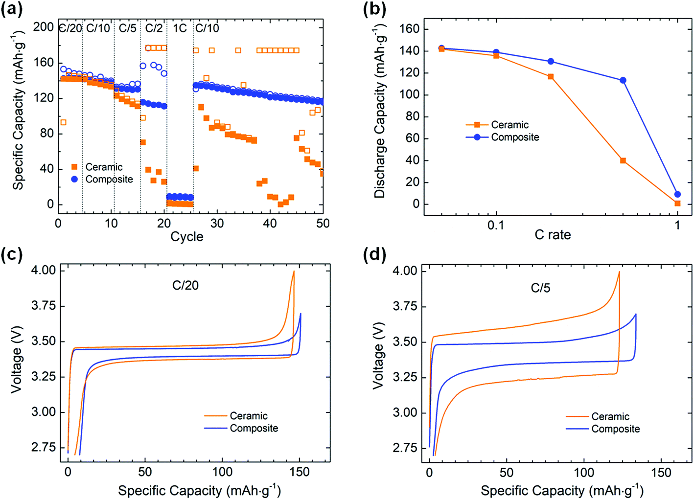 | ||
| Fig. 3 (a) Specific charge (open symbol) and discharge (full symbol) capacities at various C rates, (b) discharge rate capability, and voltage profiles at (c) C/20 and (d) C/5 for the ceramic and the composite electrolyte cells. | ||
In the case of a LLZO electrolyte, our rate capability results are similar to the values previously reported for fully solid state batteries (cycled at a similar temperature) albeit our study is performed under a current loading five times higher.14,15 For the composite membrane, our rate capability results are also similar to the ones reported in prior studies, from C/20 to C/2,19,20,22,28,29 but do fall below at 1C due to a lower upper cut off voltage and our higher active material loading at the cathode, the latter being a necessity to achieve high energy density, as will be discussed later.
It is worth noting that, in a full cell configuration, both electrolytes are able to cycle at higher current densities and for longer periods of time than in Li metal symmetric cells, which showed cell failure at C/10 and C/20 for the ceramic and the composite electrolyte, respectively. This suggests a limitation in the way in which the Li metal–electrolyte interface is evaluated, the results not being representative of how much current density this interface can withstand. A modification of the experimental design of the Li metal symmetric cell may provide more accurate assessment of this interface and will be proposed in the future.
Although the ionic conductivity of the ceramic is one order of magnitude higher than that of the composite at 70 °C (2.5 × 10⁻³ and 1.7 × 10⁻⁴ S cm−1, respectively), the ceramic pellet is 25 times thicker than the composite membrane, leading to a more resistive electrolyte in the full cell configuration. Additionally, the soft composite membrane allows better contact with the electrodes in comparison to the rigid ceramic pellet, which will facilitate the ionic transfer at high C-rates. This difference in interfacial contact could also contribute to the poorer performances of the ceramic electrolyte cell as it also increases the total cell resistance. This is clearly highlighted when looking at the voltage profiles obtained for each electrolyte at different C rates (Fig. 3c and d). At C/20, both electrolytes display a similar polarization, with ≈100 and ≈60 mV for the ceramic and composite electrolyte, respectively. At C/5, a difference appears with a polarization 2.5 times higher for the ceramic than for the composite (≈380 and ≈150 mV, respectively). Therefore, even though an electrolyte provides a higher ionic conductivity at a specific temperature, it does not guarantee better cycling performance in a Li metal solid state battery.
Cycle life at C/10
The capacity retention of the two systems was studied at a constant current (C/10) and 70 °C. The cycling performances of the ceramic and the composite electrolytes are very distinct and present unexpected behavior (Fig. 4a). During the first cycles, the discharge capacity slowly increases for both systems, suggesting that, despite the 24 hour rest, some conditioning of the cells may be required to activate all of the LFP particles and achieve higher cycling performances at C/10. The capacity retention of the SSB based on the ceramic electrolyte presents unpredicted variations. After 15 cycles, the discharge capacity decreases from 100 to 80 mA h g−1 for over ≈10 cycles, followed by a slow but constant increase before reaching the maximum capacity value at cycle no. 75. After this point, the capacity starts fading progressively. This behavior is in clear contrast with the unstable performance of the ceramic observed at C/10 after the rate capability test (Fig. 3a), which corroborates the possible degradation of the ceramic electrolyte and/or of the ceramic electrolyte–electrode interfaces under high current densities. On the other hand, the SSB based on the composite electrolyte reaches the highest capacity value after 25 cycles, after which point the capacity decreases constantly.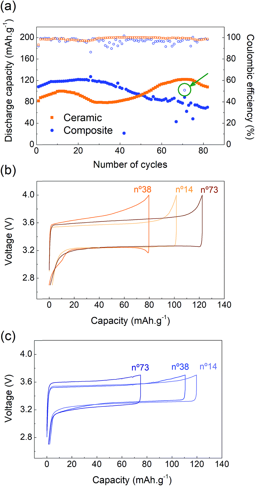 | ||
| Fig. 4 (a) Discharge capacity retention (full symbol) and coulombic efficiency (open symbol) of the ceramic and the composite based SSB at C/10. Galvanostatic charge and discharge curves of the SSB based on (b) a ceramic and (c) a composite electrolyte at selected cycle numbers. | ||
Both systems present a maximum charge capacity of 125 mA h g−1, corresponding to about 75% of the theoretical capacity (170 mA h g−1). This indicates that not all the lithium ions are extracted during the charging process. Some LFP particles may be poorly connected to the electronic and/or ionic conducting networks and are not able to oxidize/delithiate. As observed in the rate capability section, the electrochemical performance decreases as the C-rate increases, suggesting that the redox reaction is kinetically limited. Indeed, in this work, a low amount of electronic conductive additive (5 wt% of C65) is used, which most probably leads to an inhomogeneous electronic network. However, it is worth pointing out that, in Fig. 3a, the capacities recorded at C/10 during the rate capability experiment presented a maximum value of ≈140 mA h g−1 indicating that a conditioning procedure, starting at lower current densities, may be necessary to activate a larger fraction of LFP particles.
Despite the capacity variation, the coulombic efficiency of the ceramic electrolyte is very stable whereas the one of the composite electrolyte shows some instability. Voltage profiles of the ceramic cell were extracted at key moments of the experiment: at the beginning of the test (cycle no. 14), at the minimum capacity point (cycle no. 38) and after recovery (cycle no. 73) (Fig. 4b). The charge and discharge cycling profiles are smooth and representative of the LFP electrochemical activity. However, some variation in the cell polarization is observed. The cell polarization is a reflection of the total cell resistance, which is strongly affected by the solid–solid interfaces in the case of a SSB. On discharge, the polarization remains constant for all three selected cycles, suggesting even and homogeneous electrochemical processes at the electrode–electrolyte interfaces during Li metal stripping and/or cathode lithiation. The lower capacity of cycle no. 38 is associated with a higher polarization on charge indicating more resistive solid–solid interfaces during Li metal plating and/or cathode delithiation. Additional work would be needed to further elucidate and understand those differences.
For the composite electrolyte, the polarization increases with the cycle number and, as for the ceramic cell, is more pronounced on charge, which leads to a loss of capacity (Fig. 4c). An increase in polarization is recorded at the end of the discharge process, i.e. after an important amount of Li has been stripped, and could therefore be related to a loss of contact between lithium metal and the membrane, resulting in higher resistance at the anode interface. Some drops in the discharge capacity values (cycles # 42, 67, 72, 75) can be observed and are associated with a sudden increase in the current provided by the potentiostat, which leads to the cell reaching 3.7 V earlier. This sudden current increase is related to misbehaviour of the potentiostat and is not representative of the cell performance. Further sporadic instabilities with a coulombic efficiency as low as 51% are measured such as in cycle 71 (Fig. 4a, arrow). The voltage profile of this cycle shows abnormal charging with a sudden drop in polarization suggesting a drop in the cell resistance (Fig. S6, ESI†). This coulombic efficiency instability is observed about 20 times within the first 80 charges of the composite cell and is associated with the cell being in charge for an extended amount of time. In some cases, it allows for extraction of additional Li+ and therefore leads to higher discharge capacities (cycles # 25, 39, 56). However, the longer charging time can also lead to the degradation of some organic components of the cell, such as the polymer or the salt of the membrane, or to Li0 deposition within the electrolyte cross section, resulting in the accelerated aging of the cell. Post-mortem analysis could help further understanding this phenomenon and will be studied in future work. Finally, it can be noticed that the polarization of the ceramic electrolyte is higher than that of the composite electrolyte (200 mV versus 150 mV). As previously mentioned, the thick ceramic electrolyte (1000 μm) presents a higher resistance than the composite membrane (40 μm) despite the higher conductivity of the former.
Energy density and comparison with targeted values
In order to assess the potential future of each system, their theoretical specific and volumetric energy densities were evaluated. The system containing the composite electrolyte leads to energy densities of 181 W h kg−1 and 336 W h L−1, thanks to its low thickness (40 μm). In comparison the energy density of the system with the ceramic electrolyte drops to values of 7 W h kg−1 and 32 W h L−1, well below the industrial requirements for a competitive system, due to its considerable thickness (1000 μm). It would be necessary to decrease the thickness of the ceramic electrolyte to 15 μm in order to achieve the same specific energy density value than that of the composite system, maintaining the loading at 1 mA h cm−2 (Fig. 5a). However, obtaining such a thin electrolyte with a competitive ionic conductivity, let aside via an affordable and scalable processing technique, remains a Holy Grail that has not been achieved yet.30,31 On the other hand, considering a given electrolyte thickness and a specific electrode loading and composition, the volumetric energy density is equal for the two systems as it is not influenced by the density of the electrolyte but only by its thickness.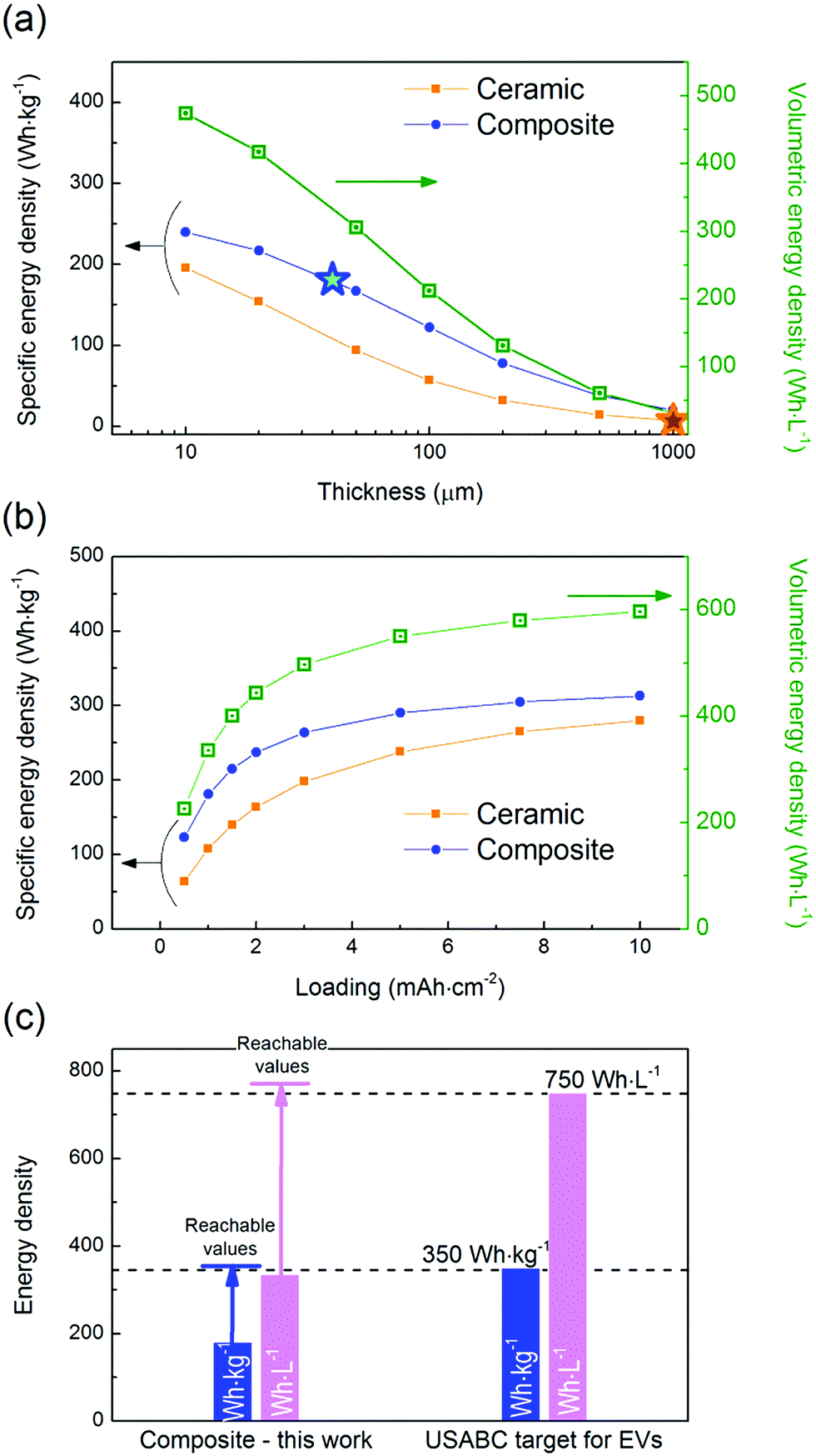 | ||
| Fig. 5 Evolution of the specific (orange and blue traces for the ceramic and the composite electrolytes, respectively) and volumetric (green trace for both the ceramic and the composite electrolytes) energy densities as a function of (a) the electrolyte thickness for a cathode loading of 1 mA h cm−2 and (b) the cathode loading for an electrolyte thickness of 40 μm. The stars indicate the specific energy densities obtained in this work. (c) Comparison of the specific and volumetric energy densities obtained in this work for the composite electrolyte with the targeted values defined by the USABC.32 The arrows represent the values reachable with the current technology using a NMC cathode (61 vol% i.e. 77 wt%) with a loading of 4 mA h cm−2 and a composite electrolyte thickness of 20 μm. | ||
In addition to the electrolyte thickness and density, the areal capacity of the cathode will strongly affect the energy density of the cells. It is interesting to point out that, for an electrolyte thickness of 40 μm, an increase in the cathode loading from 1 to 4 mA h cm−2 has a strong impact on the specific energy density value – raising it from 181 to 279 W h kg−1 for the composite electrolyte (Fig. 5b). However, targeting higher loadings is not as effective in terms of energy density improvement – with 313 W h kg−1 at 10 mA h cm−2 for the composite electrolyte – and will be more challenging to achieve from the technological point of view. On another note, it is worth highlighting that, at high loading values, a non-negligible amount of lithium will be plated/stripped at the anode interface. This amount corresponds to 5 and 50 μm in the case of a cathode loading of 1 and 10 mA h cm−2, respectively. When LFP is used as the cathode active material, cells are assembled in a discharged state; therefore lithium is extracted from the cathode and plated at the anode interface during the first electrochemical activation, i.e. during the first charge. In our calculations, the anode capacity was fixed to three times the loading of the cathode to guarantee an excess of lithium as previously recommended for primary Li metal batteries.1 However such an excess of lithium may not be necessary and, in such case, the energy densities reported here could be underestimated.
The gravimetric and volumetric energy densities for the composite cell reported in this work (181 W h kg−1 and 336 W h L−1) are lower than the values targeted by the U.S. Advanced Battery Consortium (USABC) for electric vehicle application, with a goal of 350 W h kg−1 and 750 W h L−1 at the cell level (Fig. 5c).32 Those values cannot be achieved with the electrolyte thickness used in this study (40 μm), even with a cathode loading as high as 10 mA h cm−2 (Fig. 5b). In fact, it would be necessary to comply with the following three requisites to achieve such high energy densities: (1) to decrease the electrolyte thickness to <20 μm, (2) to increase the cathode loading to >4 mA h cm−2, and (3) to replace LFP by a high voltage cathode such as Li(Ni, Mn, Co)O2 (NMC), Li(Ni, Co, Al)O2 (NCA) or LiCoO2. Additional optimization such as a decrease of the Li metal excess and of the amount of catholyte would also have a positive impact on the energy density. Future work will include the use of a high voltage cathode with the goal not only to reach the USABC target values, but also to further assess the feasibility of this technology.
Conclusions
In this first comparison of a LLZO electrolyte with a PEO-LiTFSI:LLZO composite electrolyte, Li metal solid state batteries were evaluated at 70 °C with a LFP cathode prepared at a loading of 1 mA h cm−2. No liquid or gel catholyte was necessary to promote the contact at the positive electrode thanks to the presence of a solid ionic conductivity network in the cathode. The LLZO ceramic electrolyte offers higher ionic conductivity and can withstand higher current densities in a Li metal symmetric cell in comparison to the composite membrane. However, the LLZO electrolyte provides a poorer rate capability in full cell configuration probably due to its larger thickness – 25 times thicker than the composite membrane – high stiffness, and therefore poor contact with the electrodes, which could both lead to the observed cell polarization increase. At C/10, the cycle life of the two electrolytes is comparable but the discharge capacities of the ceramic remain lower than the one of the composite membrane. It was however noticed that the voltage profile of the LLZO electrolyte was more stable than that of the composite membrane, possibly indicating a higher (electro)chemical stability of the former. The estimated energy density of the system based on the composite membrane (181 W h kg−1 and 336 W h L−1) is considerably higher than that of the one based on the LLZO ceramic (7 W h kg−1 and 32 W h L−1), due to the presence of a thinner and lighter electrolyte. Despite the encouraging results obtained in this work, the energy densities of the studied systems remain far from the requisites of the electric vehicle industry (350 W h kg−1 and 700 W h L−1). Those values will be challenging to achieve, in particular for the ceramic, mainly due to the requirement to combine a high cathode loading (≥4 mA h cm−2) with a thin electrolyte (≤20 μm). The switch from LFP to a high voltage cathode material is also compulsory to reach these objectives. Future effort will be made to pursue those targeted values.
Conflicts of interest
There are no conflicts to declare.Acknowledgements
This research was carried out at CIC Energigune (Spain) and was funded by Gobierno Vasco, within the project framework ELKARTEK CIC ENERGIGUNE 2015. A. L. also thanks IKERBASQUE for financial support. Funding by the German Federal Ministry of Education and Research (GLANZ, project number 03X4623A; FELIZIA: 03XP0026D) is appreciated.References
- K. Brandt, Historical Development of Secondary Lithium Batteries, Solid State Ionics, 1994, 69, 173–183 CrossRef.
- A. Varzi, R. Raccichini, S. Passerini and B. Scrosati, Challenges and Prospects of the Role of Solid Electrolytes in the Revitalization of Lithium Metal Batteries, J. Mater. Chem. A, 2016, 4, 17251–17259 RSC.
- J. Janek and W. G. Zeier, A Solid Future for Battery Development, Nat. Energy, 2016, 1, 16141 CrossRef.
- E. Bekaert, L. Buannic, U. Lassi, A. Llordés and J. Salminen, Chapter One - Electrolytes for Li- and Na-Ion Batteries: Concepts, Candidates, and the Role of Nanotechnology A2, In Emerging Nanotechnologies in Rechargeable Energy Storage Systems, ed. L. M. Rodriguez-Martinez and N. Omar, Elsevier, Boston, 2017, pp. 1–43 Search PubMed.
- C. Bernuy-Lopez, W. Manalastas, J. M. Lopez del Amo, A. Aguadero, F. Aguesse and J. A. Kilner, Atmosphere Controlled Processing of Ga-Substituted Garnets for High Li-Ion Conductivity Ceramics, Chem. Mater., 2014, 26, 3610–3617 CrossRef.
- L. Buannic, B. Orayech, J.-M. López Del Amo, J. Carrasco, N. A. Katcho, F. Aguesse, W. Manalastas, W. Zhang, J. Kilner and A. Llordés, Dual Substitution Strategy to Enhance Li+ Ionic Conductivity in Li7La3Zr2O12 Solid Electrolyte, Chem. Mater., 2017, 29, 1769–1778 CrossRef.
- Y. Zhu, X. He and Y. Mo, Origin of Outstanding Stability in the Lithium Solid Electrolyte Materials: Insights from Thermodynamic Analyses Based on First-Principles Calculations, ACS Appl. Mater. Interfaces, 2015, 7, 23685–23693 CrossRef PubMed.
- W. D. Richards, L. J. Miara, Y. Wang, J. C. Kim and G. Ceder, Interface Stability in Solid-State Batteries, Chem. Mater., 2016, 28, 266–273 CrossRef.
- F. Langer, I. Bardenhagen, J. Glenneberg and R. Kun, Microstructure and Temperature Dependent Lithium Ion Transport of Ceramic–Polymer Composite Electrolyte for Solid-State Lithium Ion Batteries Based on Garnet-Type Li7La3Zr2O12, Solid State Ionics, 2016, 291, 8–13 CrossRef.
- S. H.-S. Cheng, K.-Q. He, Y. Liu, J.-W. Zha, M. Kamruzzaman, R. L.-W. Ma, Z.-M. Dang, R. K. Y. Li and C. Y. Chung, Electrochemical Performance of All-Solid-State Lithium Batteries Using Inorganic Lithium Garnets Particulate Reinforced Peo/Liclo4 Electrolyte, Electrochim. Acta, 2017, 253, 430–438 CrossRef.
- M. Keller, G. B. Appetecchi, G.-T. Kim, V. Sharova, M. Schneider, J. Schuhmacher, A. Roters and S. Passerini, Electrochemical Performance of a Solvent-Free Hybrid Ceramic-Polymer Electrolyte Based on Li7La3Zr2O12 in P(Eo)15litfsi, J. Power Sources, 2017, 353, 287–297 CrossRef.
- F. Aguesse, W. Manalastas, L. Buannic, J. M. Lopez del Amo, G. Singh, A. Llordés and J. Kilner, Investigating the Dendritic Growth During Full Cell Cycling of Garnet Electrolyte in Direct Contact with Li Metal, ACS Appl. Mater. Interfaces, 2017, 9, 3808–3816 CrossRef PubMed.
- H. W. Kim, P. Manikandan, Y. J. Lim, J. H. Kim, S.-C. Nam and Y. Kim, Hybrid Solid Electrolyte with the Combination of Li7La3Zr2O12 Ceramic and Ionic Liquid for High Voltage Pseudo-Solid-State Li-Ion Batteries, J. Mater. Chem. A, 2016, 4, 17025–17032 RSC.
- F. Du, N. Zhao, Y. Li, C. Chen, Z. Liu and X. Guo, All Solid State Lithium Batteries Based on Lamellar Garnet-Type Ceramic Electrolytes, J. Power Sources, 2015, 300, 24–28 CrossRef.
- Y. Zhang, F. Chen, D. Yang, W. Zha, J. Li, Q. Shen, X. Zhang and L. Zhang, High Capacity All-Solid-State Lithium Battery Using Cathodes with Three-Dimensional Li+ Conductive Network, J. Electrochem. Soc., 2017, 164, A1695–A1702 CrossRef.
- W. Zhou, S. Wang, Y. Li, S. Xin, A. Manthiram and J. B. Goodenough, Plating a Dendrite-Free Lithium Anode with a Polymer/Ceramic/Polymer Sandwich Electrolyte, J. Am. Chem. Soc., 2016, 138, 9385–9388 CrossRef PubMed.
- J.-H. Choi, C.-H. Lee, J.-H. Yu, C.-H. Doh and S.-M. Lee, Enhancement of Ionic Conductivity of Composite Membranes for All-Solid-State Lithium Rechargeable Batteries Incorporating Tetragonal Li7La3Zr2O12 into a Polyethylene Oxide Matrix, J. Power Sources, 2015, 274, 458–463 CrossRef.
- X. Zhang, T. Liu, S. Zhang, X. Huang, B. Xu, Y. Lin, B. Xu, L. Li, C.-W. Nan and Y. Shen, Synergistic Coupling between Li6.75La3Zr1.75Ta0.25O12 and Poly(Vinylidene Fluoride) Induces High Ionic Conductivity, Mechanical Strength, and Thermal Stability of Solid Composite Electrolytes, J. Am. Chem. Soc., 2017, 139, 13779–13785 CrossRef PubMed.
- Y.-C. Jung, S.-M. Lee, J.-H. Choi, S. S. Jang and D.-W. Kim, All Solid-State Lithium Batteries Assembled with Hybrid Solid Electrolytes, J. Electrochem. Soc., 2015, 162, A704–A710 CrossRef.
- Y.-C. Jung, M.-S. Park, C.-H. Doh and D.-W. Kim, Organic-Inorganic Hybrid Solid Electrolytes for Solid-State Lithium Cells Operating at Room Temperature, Electrochim. Acta, 2016, 218, 271–277 CrossRef.
- V. Thangadurai, S. Narayanan and D. Pinzaru, Garnet-Type Solid-State Fast Li Ion Conductors for Li Batteries: Critical Review, Chem. Soc. Rev., 2014, 43, 4714–4727 RSC.
- R.-J. Chen, Y.-B. Zhang, T. Liu, B.-Q. Xu, Y.-H. Lin, C.-W. Nan and Y. Shen, Addressing the Interface Issues in All-Solid-State Bulk-Type Lithium Ion Battery Via an All-Composite Approach, ACS Appl. Mater. Interfaces, 2017, 9, 9654–9661 CrossRef PubMed.
- C.-Z. Zhao, X.-Q. Zhang, X.-B. Cheng, R. Zhang, R. Xu, P.-Y. Chen, H.-J. Peng, J.-Q. Huang and Q. Zhang, An Anion-Immobilized Composite Electrolyte for Dendrite-Free Lithium Metal Anodes, Proc. Natl. Acad. Sci. U. S. A., 2017, 114, 11069–11074 CrossRef PubMed.
- K. Park, B.-C. Yu, J.-W. Jung, Y. Li, W. Zhou, H. Gao, S. Son and J. B. Goodenough, Electrochemical Nature of the Cathode Interface for a Solid-State Lithium-Ion Battery: Interface between LiCoO2 and Garnet-Li7La3Zr2O12, Chem. Mater., 2016, 28, 8051–8059 CrossRef.
- F. Yonemoto, A. Nishimura, M. Motoyama, N. Tsuchimine, S. Kobayashi and Y. Iriyama, Temperature Effects on Cycling Stability of Li Plating/Stripping on Ta-Doped Li7La3Zr2O12, J. Power Sources, 2017, 343, 207–215 CrossRef.
- A. Sharafi, H. M. Meyer, J. Nanda, J. Wolfenstine and J. Sakamoto, Characterizing the Li–Li7La3Zr2O12 Interface Stability and Kinetics as a Function of Temperature and Current Density, J. Power Sources, 2016, 302, 135–139 CrossRef.
- C.-L. Tsai, V. Roddatis, C. V. Chandran, Q. Ma, S. Uhlenbruck, M. Bram, P. Heitjans and O. Guillon, Li7La3Zr2O12 Interface Modification for Li Dendrite Prevention, ACS Appl. Mater. Interfaces, 2016, 8, 10617–10626 CrossRef PubMed.
- B. Chen, Z. Huang, X. Chen, Y. Zhao, Q. Xu, P. Long, S. Chen and X. Xu, A New Composite Solid Electrolyte Peo/Li10gep2s12/Sn for All-Solid-State Lithium Battery, Electrochim. Acta, 2016, 210, 905–914 CrossRef.
- Y. Zhao, Z. Huang, S. Chen, B. Chen, J. Yang, Q. Zhang, F. Ding, Y. Chen and X. Xu, A Promising Peo/Lagp Hybrid Electrolyte Prepared by a Simple Method for All-Solid-State Lithium Batteries, Solid State Ionics, 2016, 295, 65–71 CrossRef.
- S. Lobe, C. Dellen, M. Finsterbusch, H. G. Gehrke, D. Sebold, C. L. Tsai, S. Uhlenbruck and O. Guillon, Radio Frequency Magnetron Sputtering of Li7La3Zr2O12 Thin Films for Solid-State Batteries, J. Power Sources, 2016, 307, 684–689 CrossRef.
- R. Inada, T. Okada, A. Bando, T. Tojo and Y. Sakurai, Properties of Garnet-Type Li6La3ZrTaO12 Solid Electrolyte Films Fabricated by Aerosol Deposition Method, Prog. Nat. Sci.: Mater. Int., 2017, 27, 350–355 CrossRef.
- United States Advanced Battery Consortium, Ev Battery Goals, http://www.uscar.org/guest/article_view.php?articles_id=85, (accessed November 2017).
Footnote |
| † Electronic supplementary information (ESI) available. See DOI: 10.1039/c8se00273h |
| This journal is © The Royal Society of Chemistry 2018 |