 Open Access Article
A general electrochemical strategy for the Sandmeyer reaction†
Qianyi
Liu
a,
Beiqi
Sun
a,
Zheng
Liu
b,
Yi
Kao
b,
Bo-Wei
Dong
b,
Shang-Da
Jiang
 b,
Feng
Li
c,
Guoquan
Liu
 c,
Yang
Yang
 d and
Fanyang
Mo
 *a
*a
aDepartment of Energy and Resources Engineering, College of Engineering, Peking University, Beijing 100871, China. E-mail: fmo@pku.edu.cn
bBeijing National Laboratory for Molecular Sciences, College of Chemistry and Molecular Engineering, Peking University, Beijing 100871, China
cState Key Laboratory of Natural and Biomimetic Drugs, School of Pharmaceutical Sciences, Peking University, Beijing 100871, China
dDepartment of Chemistry, University of California, Berkeley, CA 94720, USA
First published on 17th September 2018
Abstract
Herein we report a general electrochemical strategy for the Sandmeyer reaction. Using electricity as the driving force, this protocol employs a simple and inexpensive halogen source, such as NBS, CBrCl3, CH2I2, CCl4, LiCl and NaBr for the halogenation of aryl diazonium salts. In addition, we found that these electrochemical reactions could be performed using anilines as the starting material in a one-pot fashion. Furthermore, the practicality of this process was demonstrated in the multigram scale synthesis of aryl halides using highly inexpensive graphite as the electrode. A series of detailed mechanism studies have been performed, including radical clock and radical scavenger study, cyclic voltammetry analysis and in situ electron paramagnetic resonance (EPR) analysis.
Introduction
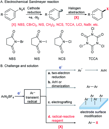
The Sandmeyer reaction represents a fundamentally important method to convert an aryl amine to an aryl halide via the intermediacy of a diazonium salt.1 Discovered in 1884,2,3 this century-old transformation is still being extensively used in modern organic synthesis in both academic and industrial settings.4–8 To date, many synthetically useful variants of the Sandmeyer reaction have been reported, including a copper metal mediated process (Gattermann reaction),9 diazotization in organic phases (Doyle diazotization),10,11 a Cu(I)-catalyzed process12 and acetate-facilitated metal-free halogenation.13 Despite these valuable advances,9–15 the development of a new strategy for the Sandmeyer reaction is still of great importance.The past decade has witnessed resurging interest in organic electrochemistry that dramatically improved organic chemists' ability for green and sustainable synthesis.16–29 Our laboratory has been engaged in the development of organic electrochemistry to overcome unmet synthetic challenges.30,31 In this context, we have recently become interested in electrocatalytic transformations of diazonium salts (Scheme 1A). An efficient electrochemical method for the Sandmeyer reaction is hampered by several factors. First, diazonium salts can engage in undesired two-electron reduction,32,33 leading to the formation of an aryl anion that could be easily protonated to give a reduction product (Scheme 1B(a)). Second, known as the Gomberg–Bachmann reaction,34 the transient aryl radical intermediate can react with an arene or another aryl radical to give a biaryl side product (Scheme 1B(b)).35 Third, the well-documented reaction of diazonium salts with the electrode can alter its properties and reduce the efficiency of electrochemical processes (Scheme 1B(c)).36–38 We envision that the regulation of electric current to control the rate of aryl radical generation and the judicious choice of halogenation reagents to rapidly intercept the nascent aryl radical would be the key to this electrochemical Sandmeyer reaction (Scheme 1B(d)). In this report, we demonstrate a general electrochemical strategy for the Sandmeyer halogenation of aryl diazonium salts.
Results and discussion
The electrochemical bromination of aryldiazonium tetrafluoroborate 1a was selected as the model reaction with N-bromosuccinimide (NBS) as the halogen source. The results are depicted in Table 1 (entries 1–7). Acetonitrile and DMF were first evaluated due to the good solubility of substrates and electrolytes in these solvents. Under these conditions, the desired product ethyl 4-bromobenzoate (2a) was formed in low yields (entries 1 and 2). The major byproduct was found to be ethyl benzoate as indicated by GC-MS analysis of the crude reaction mixture, showing that protonation or hydrogen abstraction11 was the major undesired pathway. We then evaluated other solvents, and the use of a mixed solvent system consisting of MeOH and DMF (entries 3–6) provided a higher yield of 2a. Under the optimized reaction conditions using a 5![[thin space (1/6-em)]](https://www.rsc.org/images/entities/char_2009.gif) :
:![[thin space (1/6-em)]](https://www.rsc.org/images/entities/char_2009.gif) 1 (v/v) mixture of MeOH/DMF as the solvent, Bu4NClO4 as the electrolyte and a constant current of 10 mA and a time of 3 h (3.7 F mol−1 electricity), the desired bromination product (2a) was formed in 83% yield. Finally, control experiments were conducted without current (entry 7), and a significantly lower yield of 2a was observed. This demonstrated that the desired product was predominantly obtained from the electrochemical process.
1 (v/v) mixture of MeOH/DMF as the solvent, Bu4NClO4 as the electrolyte and a constant current of 10 mA and a time of 3 h (3.7 F mol−1 electricity), the desired bromination product (2a) was formed in 83% yield. Finally, control experiments were conducted without current (entry 7), and a significantly lower yield of 2a was observed. This demonstrated that the desired product was predominantly obtained from the electrochemical process.
| Entrya | Solvent | I (mA) | Yieldb (%) |
|---|---|---|---|
| a Reaction conditions: 1a (0.3 mmol), halogenation reagent [X], electrolyte (0.25 mmol, 0.83 equiv.), solvent (3 mL), 20 °C, and 3 h. cc, constant current. Pt mesh electrodes (1 cm2 each, 52 mesh) were used. b GC-FID yields using decane as an internal standard. Isolated yields in parentheses. c 15 h. d MeCN (3 mL) as the solvent and nickel foam (1 cm2) as the cathode. | |||
| 1 | MeCN | 10 | Trace |
| 2 | DMF | 10 | 34 |
| 3 | MeOH/DMF 10![[thin space (1/6-em)]](https://www.rsc.org/images/entities/char_2009.gif) : :![[thin space (1/6-em)]](https://www.rsc.org/images/entities/char_2009.gif) 1 1 |
10 | 51 |
| 4 | MeOH/DMF 10![[thin space (1/6-em)]](https://www.rsc.org/images/entities/char_2009.gif) : :![[thin space (1/6-em)]](https://www.rsc.org/images/entities/char_2009.gif) 1 1 |
25 | 73 |
| 5 | MeOH/DMF 10![[thin space (1/6-em)]](https://www.rsc.org/images/entities/char_2009.gif) : :![[thin space (1/6-em)]](https://www.rsc.org/images/entities/char_2009.gif) 1 1 |
50 | 58 |
| 6 |
MeOH/DMF 5![[thin space (1/6-em)]](https://www.rsc.org/images/entities/char_2009.gif) : :![[thin space (1/6-em)]](https://www.rsc.org/images/entities/char_2009.gif) 1 1 |
10 | 83 (73) |
| 7 | MeOH/DMF 5![[thin space (1/6-em)]](https://www.rsc.org/images/entities/char_2009.gif) : :![[thin space (1/6-em)]](https://www.rsc.org/images/entities/char_2009.gif) 1 1 |
0 | 20, 31c |
| Entry | [I] | I (mA) | Yieldb (%) |
|---|---|---|---|
| 8 | NIS | 10 | 37 |
| 9 | CH2I2 | 10 | (87) |
| 10 | CH2I2 | 0 | 14 |
The iodination of 1a was next examined (entries 8–10). Compared with N-iodosuccinimide (NIS) (entry 8), CH2I2 was found to be a better iodinating agent in this electrochemical reaction. The desired product (3a) was obtained in 87% isolated yield under the optimized conditions (entry 9). Again, this iodination was unambiguously driven by electricity as revealed by the control experiment (entry 10).
Compared with bromination and iodination, the electrochemical chlorination of diazonium salts was more challenging. Due to the higher electronegativity of chlorine, NCS39 and TCCA40 behaved more like oxidants rather than chlorine donors. Inspired by Lin's recent work on the electrocatalytic chlorination of alkenes,41,42 we used anodic oxidation to generate chlorine radicals from chloride anions. A series of alkali chlorides, cathode materials and solvents were evaluated. Ultimately, LiCl was found to be the optimal chlorine source with nickel as the cathode and acetonitrile as the solvent (entries 13–15).
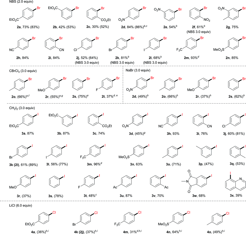
With the optimal reaction conditions, we then surveyed the substrate scope (Table 2). For bromination using NBS, aryl diazonium salts with an electron-withdrawing group, including an ester (2a–2c), a nitro (2d–2g), a cyano (2h and 2i), a halogen (2j–2l), a trifluoromethyl (2m) and a sulfonyl group (2n), furnished the corresponding brominated products in good to excellent yields. For electron-neutral or electron-rich diazonium salts, the use of NBS led to polybromination as revealed by GC-MS analysis. In these cases, CBrCl3 proved to be a better brominating agent using DMF as the solvent (2o–2t).
a Reaction conditions: 1 (0.3 mmol), Bu4NClO4 (0.25 mmol, 0.83 equiv.), CH3OH (2.5 mL) and DMF (0.5 mL), 20 °C, 3 h, and constant current 10 mA. Pt mesh electrodes (1 cm × 1 cm) were used. Isolated yields were given. GC-FID yields in parentheses were given due to either product volatility or difficulty in isolation with by-products (e.g. ArH).
b CH3OH/DMF 20![[thin space (1/6-em)]](https://www.rsc.org/images/entities/char_2009.gif) : :![[thin space (1/6-em)]](https://www.rsc.org/images/entities/char_2009.gif) 1 (total 3.0 mL).
c 1 h.
d
19F NMR yields determined using 4-(trifluoromethoxy)anisole as an internal standard.
e DMF (3 mL).
f 4.5 h.
g 2 h.
h MeCN (3 mL), LiClO4 (0.5 mmol) as the electrolyte.
i 20 mA, Ni foam cathode. 1 (total 3.0 mL).
c 1 h.
d
19F NMR yields determined using 4-(trifluoromethoxy)anisole as an internal standard.
e DMF (3 mL).
f 4.5 h.
g 2 h.
h MeCN (3 mL), LiClO4 (0.5 mmol) as the electrolyte.
i 20 mA, Ni foam cathode.
|
|---|
|
Moreover, under analogous electrochemical conditions, the iodination of aryl diazonium salts bearing an electron-withdrawing group, such as an ester (3a–3c), a cyano (3h and 3i), a halogen (3j–3l), a trifluoromethyl (3m), a sulfonyl (3n) and an acetyl (3u, 3v), gave good yields (63–96%). Additionally, electron-neutral aryl diazonium salts were also suitable substrates for this procedure (3o–3q and 3s). Finally, a range of diazonium salts (4a, 4k, 4m, 4n and 4o) could be efficiently chlorinated using LiCl as the electrochemical chlorine reagent. For instance, sulfone substituted product 4n was obtained in 64% isolated yield.
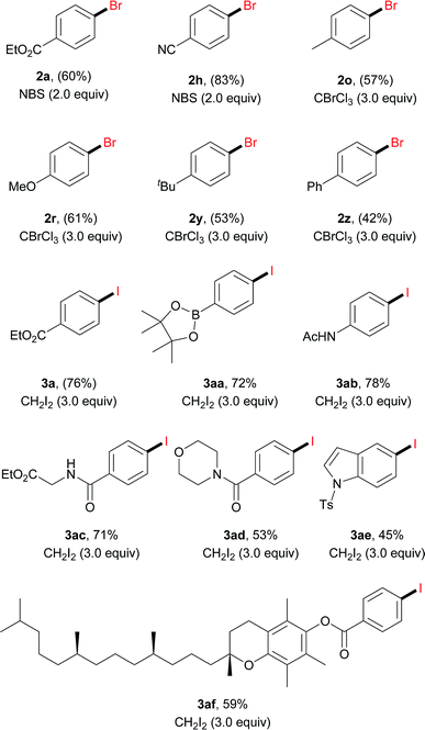
Anilines are broadly available starting materials for organic synthesis. Thus, it is highly desirable to perform an in situ diazotization/electrochemical reaction to directly employ anilines as the precursors for halogenation. As shown in Table 3, a diverse array of aryl amines were successfully transformed to the corresponding halogenated products in good to excellent yields (42–83%). This one-pot protocol tolerated a number of functional groups, such as a boronic ester (3aa), an amide (3ab–3ad) and an indole (3ae). In general, aryl amines with an electron-withdrawing group gave a relatively higher yield. For instance, bromination of 4-cyanoaniline under the one-pot protocol gave 83% GC yield (2h); iodination of N-(4-aminophenyl)acetamide gave 78% isolated yield (3ab). Moreover, it is noteworthy that the aniline derived from vitamin E was also iodinated in 59% isolated yield (3af).
| a Reaction conditions: aryl amine (0.3 mmol), tBuONO (0.33 mmol, 1.1 equiv.), HCl (5 M in Et2O, 90 μL, 0.45 mmol, 1.5 equiv.), CH3OH 2.5 mL, DMF 0.5 mL, 0 °C, and 0.5 h; then Bu4NClO4 (0.25 mmol, 0.83 equiv.), [X], 20 °C, 3 h, and constant current 10 mA. Pt mesh electrodes (1 cm × 1 cm) were used. Isolated yields were given. GC-FID yields were shown in parentheses. For details, see the ESI. |
|---|
|
To further demonstrate the utility of this electrochemical protocol, gram-scale experiments were next carried out. Since the electrochemical reduction of diazonium salts takes place at the cathode, we applied inexpensive graphite plate electrodes with a large size to lower the current density (J = 2.78 mA cm−2). By using the setup shown in Scheme 2, 2h was prepared from 1h on a three-gram scale (15 mmol) in 76% yield. Similarly, 3h was prepared on a three-gram scale in 80% yield.
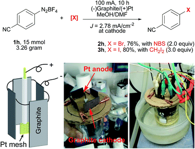 | ||
| Scheme 2 Gram-scale electrochemical Sandmeyer reactions. A Pt mesh electrode (1 cm × 1 cm, 52 mesh) as the anode, and 4 graphite plates (4 × 3 cm × 3 cm immersed in the solution) as the cathodes. | ||
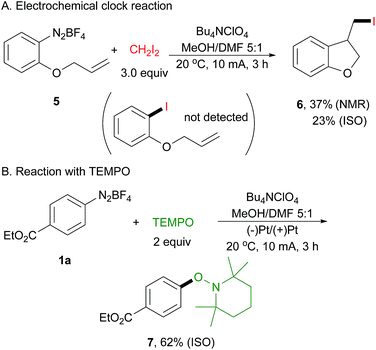
To probe this electrically generated aryl radical species, we carried out a range of mechanistic experiments. First, a radical clock experiment was performed by using diazonium salt 5 derived from 2-(allyloxy)aniline as the substrate (Scheme 3A). We obtained only the cyclized product 6 in 37% yield as determined by 1H NMR spectroscopy, and the acyclic product was not detected by GC-MS and 1H NMR analysis. Next, an electrochemical reaction of 1a with 2,2,6,6-tetramethyl-1-piperidinyloxy (TEMPO) was conducted, affording arylated product 7 in 62% isolated yield (Scheme 3B). This is well in accord with Studer's report.43 In their paper, they have demonstrated that TEMPONa is capable of reducing diazonium salt to its aryl radical, thus facilitating the following transformation.
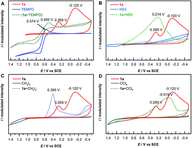
The mechanism of electrochemical reduction of diazonium salt has been studied by means of polarography.44 Here we further apply this technique in our reaction system. Thus, cyclic voltammetry (CV) measurements of 1a with a series of radical-reactive reagents were taken. The CV curve of 1a gave two waves, corresponded to the reduction of aryl diazonium to aryl radicals and further to aryl anions, respectively. This is in good agreement with a literature report.45 However the CV curves of 1a with reagents (TEMPO, NBS, CH2I2 and CCl4 in these cases, respectively) give only one reduction peak, indicating that the nascent aryl radical reacts with these reagents, and thus likely has no chance to be further reduced on the cathode (Fig. 1). These experimental results are consistent with the hypothesis shown in Scheme 1B(d).
Electron paramagnetic resonance (EPR) is a spectroscopic technique capable of detecting and identifying paramagnetic species, such as organic radicals, thus providing essential information on the nature of reactive intermediates in single electron transfer reactions. EPR spectroscopy has been extensively utilized to study electrochemically generated organic radicals.46 Here, we applied EPR spectroelectrochemistry to study the current electrochemical Sandmeyer reaction. In our setup, we combined a common Bruker Elexsys E580 spectrometer with a super-high sensitivity probe head (ω = 9.80 GHz) and a standard flat cell (0.3 mm in depth) with ultrathin Pt wires (Φ 0.2 mm) for this in situ study (Fig. 2A). Using this setup, electrolysis experiments and in situ EPR measurements were first performed on samples containing diazonium salt 1a and NBS in MeOH/DMF with n-Bu4NClO4 as the electrolyte. EPR signals were not observed, presumably due to the high reactivity and low concentration of these radical intermediates. Consequently, N-benzylidene-tert-butylamine N-oxide (PBN) was introduced into the experiments as a spin-trap.47 Spin-traps react with short-lived radicals and convert them to more stable, EPR detectable radical species. The choice of PBN is based on Bard's report,48 where they found that PBN is electroinactive between 1.5 and −2.4 V (vs. SCE). Thus, four electrochemical reactions a–d were followed by in situ EPR spectroscopy using PBN as the spin-trap (Fig. 2A). The EPR spectrum was acquired in an interval of 30 s over the course of 100 min. These EPR signals were then compiled as a time dependent 2D profile (for reaction b, see Fig. 2B; for reactions a, c and d, see Fig. S5†). Fig. 2C shows the EPR signals of these reactions at different reaction times, and Fig. 2D shows time dependent double-integrated intensity of these in situ EPR signals.
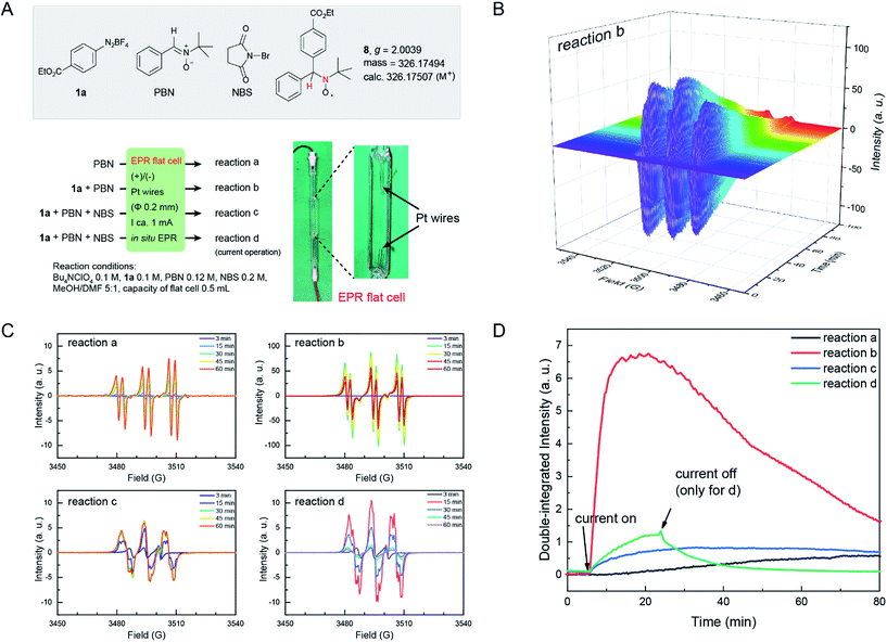 | ||
| Fig. 2 (A) Four in situ EPR electrochemical reactions. Photograph of an EPR flat cell with a home-made electrolysis setup is shown. (B) Time dependent EPR profile of reaction b. For the EPR profile of reactions a, c and d, see Fig. S5 in the ESI.† (C) EPR signal at different times of reactions a–d. (D) Time evolution of the double-integrated intensity of the signals of in situ EPR electrochemical reactions a–d. a.u., arbitrary unit. | ||
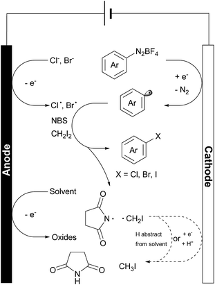
In these reactions, no major EPR signal is observed until electricity is on. The isotropic g factor and hyperfine coupling constants of these radical EPR signals were simulated using the least-squares fitting method with EasySpin's function garlic (for details, see the ESI†). As expected, radicals in reactions a, b and c are different and in d they resemble those in c (Fig. 2C). The contrasting growth rates of intensity shown in Fig. 2D provided valuable mechanistic information. By comparing reactions a and b, a rapid growth observed in reaction b indicated that diazonium salt 1a was rapidly reduced to an aryl radical upon electrolysis. The resulting aryl radical was trapped by PBN to afford an EPR active species. Based on a six-line EPR spectrum (g = 2.0039, aN = 13.02 G, and aH = 2.37 G)47,48 and HRMS data, this radical could be likely attributed to compound 8. In reactions c and d, the intensity grew slowly as compared with reaction b, indicating that the addition of NBS changes the reaction pathway of electrically generated radicals. In reaction d, the intensity rapidly decayed when the current was turned off, also demonstrating an electricity driven radical generation process. These in situ EPR electrochemical experiments and previous cyclic voltammetry studies demonstrated that diazonium salts can readily undergo single electron reduction processes on the cathode, and the resulting aryl radical is a highly reactive species that can be trapped by many radical trapping reagents, such as NBS, CH2I2, PBN and TEMPO. Meanwhile, the solvents (e.g. MeOH) can be oxidized on the anode49 to balance the overall transformation (Scheme 4).
Conclusion
In summary, we have developed a general electrochemical protocol for the Sandmeyer halogenation process. A diverse range of functional groups were compatible with this electrochemical reaction. Anilines can be directly employed as the starting material, further expanding the utility of this method. Moreover, this method is amenable to the large-scale synthesis of aryl halides, and very inexpensive graphite can be employed instead of platinum as the cathode material for this large-scale preparation. Importantly, detailed mechanism studies, including the application of rarely used in situ EPR measurements, support a single electron reduction mechanism for the halogenation of diazonium salts upon electrolysis. This electrochemical process could be a complementary method for the existing Sandmeyer halogenation reactions, and might inspire other Sandmeyer type transformations (e.g. noble metal free trifluoromethylation50–52) in the near future.Conflicts of interest
There are no conflicts to declare.Acknowledgements
We thank Prof. Chao Li at National Institute of Biological Sciences (Beijing) for insightful discussion. The project is supported by the Natural Science Foundation of China (Grants 21502003 and 21772003). We also thank the “1000-Youth Talents Plan” and Peking University for start-up funds. Y. Y. thanks the Miller Institute for Basic Research in Science at UC Berkeley for a post-doctoral fellowship.Notes and references
-
L. Kurti and B. Czakó, Strategic applications of named reactions in organic synthesis, Elsevier, 2005 Search PubMed
.
- T. Sandmeyer, Ber. Dtsch. Chem. Ges., 1884, 17, 1633–1635 CrossRef
.
- T. Sandmeyer, Ber. Dtsch. Chem. Ges., 1884, 17, 2650–2653 CrossRef
.
- H. H. Hodgson, Chem. Rev., 1947, 40, 251–277 CrossRef CAS PubMed
.
- C. Galli, Chem. Rev., 1988, 88, 765–792 CrossRef CAS
.
- E. B. Merkushev, Synthesis, 1988, 1988, 923–937 CrossRef
.
- F. Mo, G. Dong, Y. Zhang and J. Wang, Org. Biomol. Chem., 2013, 11, 1582–1593 RSC
.
- F. Mo, D. Qiu, Y. Zhang and J. Wang, Acc. Chem. Res., 2018, 51, 496–506 CrossRef CAS PubMed
.
- L. Gattermann and A. Cantzler, Ber. Dtsch. Chem. Ges., 1892, 25, 1086–1091 CrossRef
.
- M. P. Doyle, J. F. Dellaria, B. Siegfried and S. W. Bishop, J. Org. Chem., 1977, 42, 3494–3498 CrossRef CAS
.
- M. P. Doyle, B. Siegfried and J. F. Dellaria Jr, J. Org. Chem., 1977, 42, 2426–2431 CrossRef CAS
.
- I. P. Beletskaya, A. S. Sigeev, A. S. Peregudov and P. V. Petrovskii, Synthesis, 2007, 2007, 2534–2538 CrossRef
.
- D. A. Leas, Y. Dong, J. L. Vennerstrom and D. E. Stack, Org. Lett., 2017, 19, 2518–2521 CrossRef CAS PubMed
.
- J. G. Lee and H. T. Cha, Tetrahedron Lett., 1992, 33, 3167–3168 CrossRef CAS
.
- H. Yang, L. Fu, L. Wei, J. Liang and B. P. Binks, J. Am. Chem. Soc., 2015, 137, 1362–1371 CrossRef CAS PubMed
.
- K. D. Moeller, Tetrahedron, 2000, 56, 9527–9554 CrossRef CAS
.
- J. B. Sperry and D. L. Wright, Chem. Soc. Rev., 2006, 35, 605–621 RSC
.
- A. Jutand, Chem. Rev., 2008, 108, 2300–2347 CrossRef CAS PubMed
.
- J.-i. Yoshida, K. Kataoka, R. Horcajada and A. Nagaki, Chem. Rev., 2008, 108, 2265–2299 CrossRef CAS PubMed
.
- R. Francke and R. D. Little, Chem. Soc. Rev., 2014, 43, 2492–2521 RSC
.
- E. J. Horn, B. R. Rosen and P. S. Baran, ACS Cent. Sci., 2016, 2, 302–308 CrossRef CAS PubMed
.
- R. Feng, J. A. Smith and K. D. Moeller, Acc. Chem. Res., 2017, 50, 2346–2352 CrossRef CAS PubMed
.
- Y. Jiang, K. Xu and C. Zeng, Chem. Rev., 2018, 118, 4485–4540 CrossRef CAS PubMed
.
- M. Yan, Y. Kawamata and P. S. Baran, Chem. Rev., 2017, 117, 13230–13319 CrossRef CAS PubMed
.
- A. Wiebe, T. Gieshoff, S. Möhle, E. Rodrigo, M. Zirbes and S. R. Waldvogel, Angew. Chem., Int. Ed., 2018, 57, 5594–5619 CrossRef CAS PubMed
.
- S. Möhle, M. Zirbes, E. Rodrigo, T. Gieshoff, A. Wiebe and S. R. Waldvogel, Angew. Chem., Int. Ed., 2018, 57, 6018–6041 CrossRef PubMed
.
- G. S. Sauer and S. Lin, ACS Catal., 2018, 8, 5175–5187 CrossRef CAS
.
- S. Tang, Y. Liu and A. Lei, Chem, 2018, 4, 27–45 CAS
.
- S. R. Waldvogel, S. Lips, M. Selt, B. Riehl and C. J. Kampf, Chem. Rev., 2018, 118, 6706–6765 CrossRef CAS PubMed
.
- L. Zhang, Z. Zhang, J. Hong, J. Yu, J. Zhang and F. Mo, J. Org. Chem., 2018, 83, 3200–3207 CrossRef CAS PubMed
.
- L. Zhang, Z. Zhang, J. Zhang, K. Li and F. Mo, Green Chem., 2018, 20, 3916–3920 RSC
.
- E. R. Atkinson, C. E. Garland and A. F. Butler, J. Am. Chem. Soc., 1953, 75, 983–984 CrossRef CAS
.
- J. K. Kochi, J. Am. Chem. Soc., 1955, 77, 3208–3211 CrossRef CAS
.
- M. Gomberg and W. E. Bachmann, J. Am. Chem. Soc., 1924, 46, 2339–2343 CrossRef CAS
.
- E. R. Atkinson, C. R. Morgan, H. H. Warren and T. J. Manning, J. Am. Chem. Soc., 1945, 67, 1513–1515 CrossRef CAS
.
- D. Belanger and J. Pinson, Chem. Soc. Rev., 2011, 40, 3995–4048 RSC
.
- G. L. C. Paulus, Q. H. Wang and M. S. Strano, Acc. Chem. Res., 2013, 46, 160–170 CrossRef CAS PubMed
.
-
A. Berisha, M. M. Chehimi, J. Pinson and F. Podvorica, Electroanalytical Chemistry, A Series of Advances, 2015, vol. 26, pp. 115–224 Search PubMed
.
-
S. C. Virgil, T. V. Hughes, D. Qiu and J. Wang, in Encyclopedia of Reagents for Organic Synthesis, John Wiley & Sons, Ltd, 2001, DOI:10.1002/047084289X.rc145.pub3
.
-
G. A. Hiegel, G. Pozzi and AnuMahadevan, in Encyclopedia of Reagents for Organic Synthesis, John Wiley & Sons, Ltd, 2001, DOI:10.1002/047084289X.rt209.pub3
.
- N. Fu, G. S. Sauer and S. Lin, J. Am. Chem. Soc., 2017, 139, 15548–15553 CrossRef CAS PubMed
.
- K.-Y. Ye, G. Pombar, N. Fu, G. S. Sauer, I. Keresztes and S. Lin, J. Am. Chem. Soc., 2018, 140, 2438–2441 CrossRef CAS PubMed
.
- M. Hartmann, Y. Li and A. Studer, J. Am. Chem. Soc., 2012, 134, 16516–16519 CrossRef CAS PubMed
.
- R. M. Elofson and F. F. Gadallah, J. Org. Chem., 1969, 34, 854–857 CrossRef CAS
.
- E. R. Atkinson, H. H. Warren, P. I. Abell and R. E. Wing, J. Am. Chem. Soc., 1950, 72, 915–918 CrossRef CAS
.
-
P. Rapta, E. Dmitrieva, A. A. Popov and L. Dunsch, in Organic Electrochemistry: Revised and Expanded, ed. O. Hammerich and B. Speiser, CRC Press, 5 edn, 2016, ch. 3, pp. 169–190 Search PubMed
.
- G. R. Buettner, Free Radical Biol. Med., 1987, 3, 259–303 CrossRef CAS PubMed
.
- A. J. Bard, J. C. Gilbert and R. D. Goodin, J. Am. Chem. Soc., 1974, 96, 620–621 CrossRef CAS
.
- G. Sundholm, Acta Chem. Scand., 1971, 25, 3188–3189 CrossRef CAS
.
- X. Wang, Y. Xu, F. Mo, G. Ji, D. Qiu, J. Feng, Y. Ye, S. Zhang, Y. Zhang and J. Wang, J. Am. Chem. Soc., 2013, 135, 10330–10333 CrossRef CAS PubMed
.
- J.-J. Dai, C. Fang, B. Xiao, J. Yi, J. Xu, Z.-J. Liu, X. Lu, L. Liu and Y. Fu, J. Am. Chem. Soc., 2013, 135, 8436–8439 CrossRef CAS PubMed
.
- G. Danoun, B. Bayarmagnai, M. F. Grünberg and L. J. Gooßen, Angew. Chem., Int. Ed., 2013, 52, 7972–7975 CrossRef CAS PubMed
.
Footnote |
| † Electronic supplementary information (ESI) available. See DOI: 10.1039/c8sc03346c |
| This journal is © The Royal Society of Chemistry 2018 |

