DOI:
10.1039/C8SC00731D
(Edge Article)
Chem. Sci., 2018,
9, 5919-5928
Low cost and stable quinoxaline-based hole-transporting materials with a D–A–D molecular configuration for efficient perovskite solar cells†
Received
13th February 2018
, Accepted 13th June 2018
First published on 13th June 2018
Abstract
The use of expensive hole transporting materials (HTMs), such as spiro-OMeTAD, in perovskite solar cells (PSCs) is one of the critical bottlenecks to hinder their large-scale applications. Some low-cost alternatives have been developed by combining conjugated electron-rich cores with arylamine end-caps, usually in a donor–π spacer–donor (D–π–D) molecular configuration. However, incorporation of electron-rich cores can lead to undesirable up-shift in the HOMO energy level and low stability, and few of these new HTMs can outperform spiro-OMeTAD in terms of device efficiency. Given that electron-deficient units have shown many advantages in developing efficient and stable photovoltaic dyes and polymers, we herein present a couple of novel molecular quinoxaline-based HTMs (TQ1 and TQ2) with a donor–acceptor–donor (D–A–D) configuration, especially for rationally modulating the HOMO level, improving the stability and decreasing the cost. The TQ2-based PSCs exhibit a maximum efficiency of 19.62% (working area of 0.09 cm2), unprecedentedly outperforming that of spiro-OMeTAD (18.54%) under the same conditions. In comparison, TQ1 based devices only showed moderate efficiencies (14.27%). The differences in hole extraction and transportation between TQ1 and TQ2 are explored by photoluminescence quenching, mobility and conductivity tests, and single crystal analysis. The scaling-up of the TQ2 based device to 1.02 cm2 achieves a promising efficiency of 18.50%, indicative of high film uniformity and processing scalability. The significant cost advantage and excellent photovoltaic performance strongly indicate that the D–A–D featured TQ2 has great potential for future practical applications.
Introduction
In the past few years, the extensive efforts on metal halide perovskite solar cells (PSCs) have quickly advanced their solar to electric power conversion efficiency (PCE) to over 20%.1–5 The best performing PSCs have a n-i-p configuration with a perovskite absorber sandwiched between a titanium oxide semiconductor (n-type contact) and an organic hole-transporting layer (p-type contact).6 The hole-transporting material (HTM) plays a critical role in facilitating efficient charge extraction and collection in devices, and alleviating the cell degradation as a protective barrier on top of the perovskite layer.7,8 An ideal HTM for highly efficient PSCs should have suitable energy levels, uniform thin film morphology, fast hole extraction/transportation, high intrinsic stability and cost effectiveness.
Until now, the most frequently used HTM for PSCs is 2,2′,7,7′-tetrakis(N,N-di-p-methoxyphenylamine)-9,9′-spirobifluorene (spiro-OMeTAD), which exhibits the advantage of high solubility and high glass transition temperature.9–11 These merits can ensure an excellent thin film morphology. It also shows desirable hole extraction and conduction capabilities upon incorporation of some chemical additives and dopants.12 However, compared to other components in PSCs, the spiro-OMeTAD is quite costly due to its complicated multistep synthesis and sublimation-based purification, which is a bottleneck to large scale production for practical application.13,14 Moreover, the highest occupied molecular orbital (HOMO) energy level of spiro-OMeTAD (−5.13 eV)15 is not optimal for matching the valence band of the perovskite (−5.43 eV)8 due to its relatively large energy offset. As a comparison, the conduction band energy offset between the perovskite (−3.93 eV) and TiO2 (−4.0 eV) is much smaller.16,17 Although there is debate on the correlation between the open-circuit voltage (Voc) and the HOMO energy level of HTMs,18–21 a further efficiency enhancement is still highly expected by finely controlling the energetics as well as charge dynamics at this interface for minimizing the interfacial energy loss.
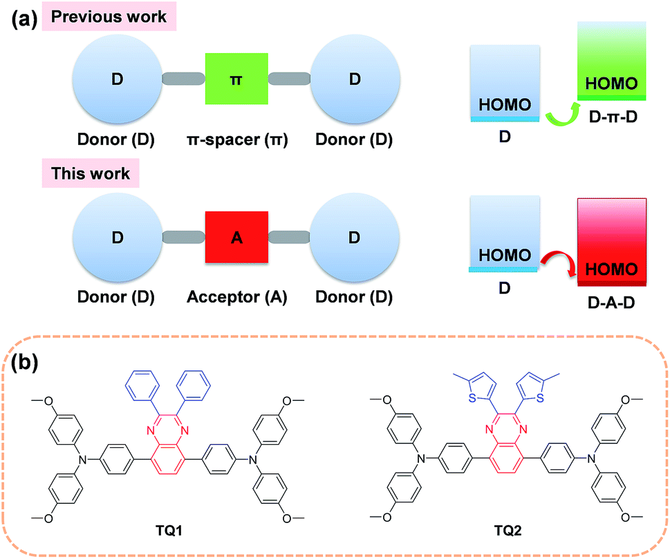
In order to decrease the cost originated from the HTM, one promising strategy is to simplify the molecular structure of spiro-OMeTAD. In this regard, a number of small molecular HTMs have been developed by coupling arylamine units (such as diphenylamine, triphenylamine (TPA), carbazole, phenothiazine and fluorene derivatives) with some structurally simple cores. In most cases, the core is a conjugated electron rich unit like pyrene,17 3,4-ethylenedioxythiophene,22 triazatruxene,19 spiro[fluorene-9,9′-xanthene],23 and thienothiophene.24 In principle, the incorporation of conjugated electron rich core units (electron donor) to construct HTMs with donor–π spacer–donor (D–π–D) configuration is not favorable for HOMO energy level optimization. According to molecular orbital hybridization theory, the introduction of an electron donor can upraise the HOMO energy level of a conjugated arylamine system (Fig. 1a), which will further enlarge the energy offset at the perovskite-HTM interface.25 Moreover, the combination of an additional electron rich unit with the arylamine groups may give rise to intrinsic stability issues due to the decreased oxidation potential.26 In contrast, the incorporation of an electron deficient core unit (electron acceptor) to form a donor–acceptor–donor (D–A–D) structure can rationally decrease the HOMO energy level and improve the intrinsic photo- and thermal-stability of the electron rich arylamine system, according to our previous experience on the design of organic sensitizers with an additional acceptor unit.27 Indeed, the use of a D–A scaffold has been demonstrated as a promising strategy for designing efficient organic HTMs28 as well as photovoltaic polymers. However, the D–A–D type HTMs have been rarely reported, and only the benzothiadiazole (BTD) unit has been attempted as the electron deficient core.29,30 It should be noted that BTD has a very strongly electron withdrawing structure that can significantly decrease the lowest unoccupied molecular orbital (LUMO) energy level and trap charges,31 which might be undesirable to the electron blocking and hole transporting capability of the HTM layer.
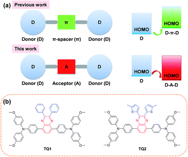 |
| | Fig. 1 (a) A schematic illustration of the shift of the HOMO energy level of D–π–D and D–A–D structured organic HTMs. (b) Chemical structures of D–A–D structured HTM TQ1 and TQ2 featuring a moderately electron deficient quinoxaline as the core. | |
With this in mind, herein we incorporate a moderately electron deficient quinoxaline unit as the core in conjunction with methoxyl substituted triphenylamine (MeOTPA) end-caps to construct novel and low cost D–A–D featured HTMs TQ1 and TQ2 (Fig. 1b). The relatively weak electron-withdrawing character of a quinoxaline core is expected to: (i) stabilize the HOMO energy level for matching well with the valence band of the perovskite, (ii) maintain a relatively high LUMO energy level for efficient electron blocking capability, and (iii) improve the intrinsic photo- and thermal-stabilities of organic HTMs.32 In addition, the quinoxaline core has the advantage of low synthetic cost, and its pyrazine heterocycle provide a facile chemical modification possibility.33,34 The substituents on the quinoxaline core are found to be critical to the photovoltaic performance, and the thienyl substituent based TQ2 shows much superiority to its phenyl analogue TQ1 in terms of hole extraction and conduction, which was rationalized by a series of comparative studies including photoluminescence (PL) quenching, hole mobility/conductivity measurement and single crystal analysis. The best performing PSCs employing TQ2 as the hole transporting layer exhibit a maximum PCE of 19.62% (area of 0.09 cm2), outperforming that of spiro-OMeTAD (18.54%) under the same conditions. We also fabricate larger size devices with a working area of 1.02 cm2, which show a champion PCE of 18.50%, indicative of an excellent alternative to the traditional spiro-OMeTAD.
Results and discussion
Enabling large cost-advantage with straightforward synthesis
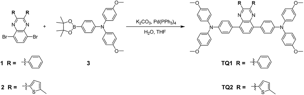
Cost effective organic HTMs should be prepared with a short synthetic route, simple reaction conditions and scalable purification methods. The synthesis procedure for TQ1 and TQ2 is shown in Scheme 1, and experimental details are provided in the ESI.† In comparison with the tedious synthesis of spiro-OMeTAD, the new HTMs can be conveniently synthesized with high yields (around 80%) by a one-step Suzuki coupling reaction between the 5,8-dibromo-quinoxaline core and the pinacol ester of the triphenylamine donor. Besides, the final products can be purified by simple recrystallization process instead of a costly sublimation method, meeting the requirements of scaling-up production. Both TQ1 and TQ2 have been fully characterized by NMR spectroscopy and high resolution mass spectrometry (Fig. S11–S16 in the ESI†). High performance liquid chromatography (HPLC) is also performed to test the purity of these two HTMs, assuring a purity of over 99.5% (Fig. S17 and S18 in the ESI†). By using the calculation mode provided in literature studies,35,36 the laboratory synthetic costs of TQ1 and TQ2 are estimated to be 14.7 and 16.7 $ g−1, respectively (Tables S1 and S2 in the ESI†), which are only 1/30 of that of spiro-OMeTAD (500 $ g−1).35 If these new materials can show comparable performance with the traditional HTM of spiro-OMeTAD, it can be expected to greatly decrease the total cost of PSCs.
 |
| | Scheme 1 The straightforward synthetic routes to TQ1 and TQ2. | |
Targeted modulation of the HOMO level upon incorporation of an electron-deficient quinoxaline core
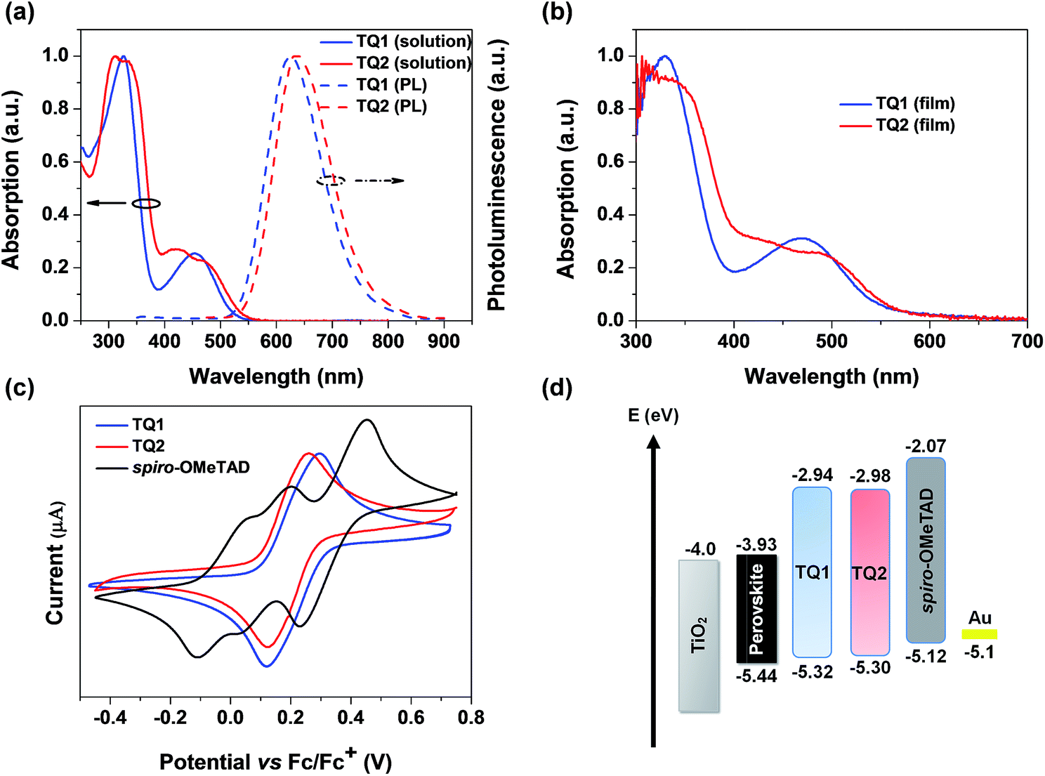
The UV-vis absorption and photoluminescence spectra of TQ1 and TQ2 in CH2Cl2 solution are depicted in Fig. 2a. TQ1 exhibits two characteristic absorption bands. The absorption band in the ultraviolet (UV) region with a peak at 327 nm can be ascribed to the π–π* electron transition of the conjugated backbone, while the other one in the visible region (454 nm) can be ascribed to the intramolecular charge transfer from the electron rich donor groups to the electron deficient quinoxaline core unit.37 Intriguingly, the absorption spectrum of TQ2 shows more complicated profiles that both bands in UV and visible regions have extra shoulder peaks. To understand the origin of these extra absorption bands of TQ2, we have further measured the absorption spectra of the synthetic intermediates 1 and 2 (Fig. S1 in the ESI†), which lack the typical electron donating groups of the triphenylamine terminal in comparison to TQ1 and TQ2. Unexpectedly, these structurally simple intermediates also showed two groups of absorption bands, and the relatively low energy absorption bands (356 nm for 1 and 415 nm for 2) should be attributed to the charge transfer transition occurred between the substituents and the quinoxaline unit. The significantly red-shifted absorption band of 2 can be rationalized by the stronger electron donating capability of the thienyl group with respect to the phenyl group in 1. We note that the quinoxaline based TQ1 and TQ2 have a typical “cross-conjugated” molecular structure, which featured two “perpendicular” π-conjugated arms connected through the central aromatic core.38 Both of the π-conjugated arms participate in the electronic transition process, and the final absorption spectra should be the superposition of electronic properties of each arm. In the horizontal direction, TQ1 and TQ2 have the same conjugation structure and thus similar electronic transitions. It is the electronic difference in the vertical direction which leads to the different superposition results between TQ1 and TQ2, as well as the appearance of shoulder peaks in the absorption spectrum of TQ2. Coincidently, the charge transfer transition from both triphenylamines and the substituents to quinoxaline can be distinguished in the absorption spectrum of TQ2, resulting in the observed complicated absorption profile. The optical bandgaps (Eg) of TQ1 and TQ2 were calculated from the intersection of the corresponding normalized absorption and emission spectra, estimated to be 2.38 and 2.32 eV, respectively. Fig. 2b shows the absorption spectra of TQ1 and TQ2 in the thin film state. Compared to their solution spectra, a slight red-shift of the absorption onset was observed for both materials, suggesting the presence of intermolecular interactions.
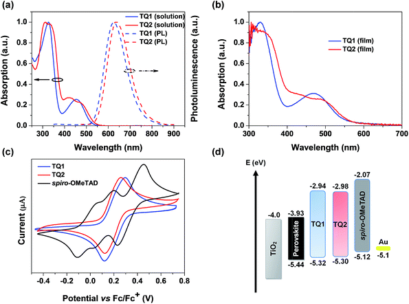 |
| | Fig. 2 (a) Absorption and emission spectra of TQ1 and TQ2 in CH2Cl2. (b) Absorption spectra of TQ1 and TQ2 in the thin film state. (c) CV spectra of TQ1, TQ2 and spiro-OMeTAD. (d) Energy-level diagram of perovskite solar cells with different HTMs (energy levels of the perovskite, TiO2 and Au are taken from ref. 8). | |
Cyclic voltammetry (CV) measurements were performed to determine the electrochemical properties of these two HTMs. TQ1 and TQ2 both exhibit a couple of highly reversible redox peaks in the scanning range (Fig. 2c), which are assigned to the oxidation of triphenylamine moieties. Besides, both TQ1 and TQ2 have pretty high electrochemical stability under repeated CV scans (Fig. S2 in the ESI†). The half-wave potential of TQ1 is 0.22 eV versus Fc/Fc+, which is almost the same with TQ2 (0.20 eV). The HOMO energy levels versus vacuum is thus calculated to be −5.32 and −5.30 eV for TQ1 and TQ2, respectively (Table 1).39 The downward shifted HOMO energy levels of TQ1 and TQ2 relative to that of spiro-OMeTAD (−5.12 eV) can be associated with the incorporation of an electron deficient quinoxaline core. Obviously, these HOMO energy levels are still positive than the valence band (VB) of the perovskite (−5.43 eV). The deep HOMO energy level is indeed beneficial to the interfacial band alignment for minimizing the voltage loss (Fig. 2d).40 The LUMO energy levels of TQ1 and TQ2 were further estimated to be −2.94 eV and −2.98 eV (Table 1), respectively, calculated by adding the optical bandgap (Eg) to the HOMO energy levels. As shown in Fig. 2d, these high LUMO energy levels relative to the conduction band bottom of the hybrid perovskite are competent for blocking electron transfer to metal back contact.10
Table 1 Photophysical and electrochemical properties of TQ1 and TQ2
| HTM |
λ
max
[nm] |
λ
em
[nm] |
E
g
[eV] |
E
HOMO
[eV] |
E
LUMO
[eV] |
|
Absorption maximum in CH2Cl2 solution.
Peak values of emission spectra in CH2Cl2 solution.
E
g was calibrated from the intersection wavelength of normalized emission and absorption spectra by 1240/λ.
The EHOMO was obtained in CH2Cl2 with ferrocene (−5.1 eV vs. vacuum) as an external reference.
Calculated by Eg + EHOMO.
|
|
TQ1
|
326![[thin space (1/6-em)]](https://www.rsc.org/images/entities/char_2009.gif) 454 454 |
629 |
2.38 |
−5.32 |
−2.94 |
|
TQ2
|
313336420469 |
639 |
2.32 |
−5.30 |
−2.98 |
Improved thermal properties with uniform morphology
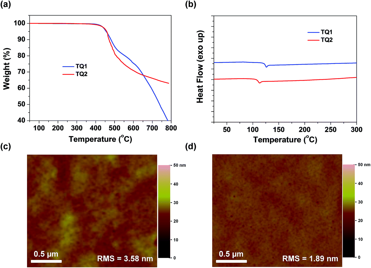
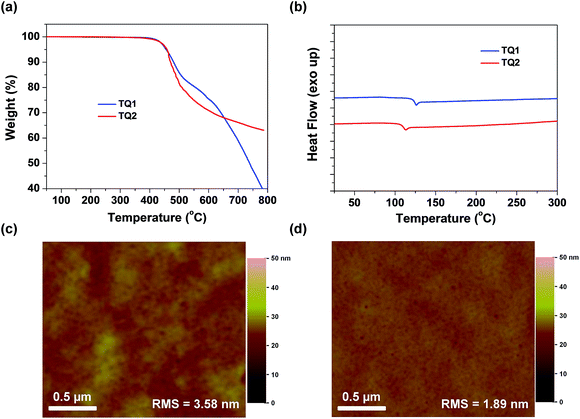
Thermogravimetric analysis (TGA) and differential scanning calorimetry (DSC) measurements were carried out to determine thermal properties of the synthesized HTMs. The corresponding results are shown in Fig. 3a and b. It is observed that D–A–D structured TQ1 and TQ2 exhibit a thermal decomposition temperature (Td) of 455 and 458 °C, respectively, which are higher than those of HTMs based on electron-rich cores, and even higher than that of spiro-OMeTAD (424 °C).39 The high Td values indicate excellent thermal stability of the D–A–D structured HTMs. DSC measurements were performed with two heating and cooling circles, and the result analysis is based on the second heating process. During the DSC scanning from room temperature to 350 °C, only one weak endothermal process was observed for both materials. The glass transition temperature (Tg) for TQ1 and TQ2 is 126 and 113 °C, respectively, keeping at the same level of spiro-OMeTAD.41 The relatively high Tg values are advantageous to the formation of a uniform thin film with the benefit of long-term morphology preservation.8Fig. 3c and d show the atomic force microscopy (AFM) images of TQ1 and TQ2 thin films spin-coated on the top of the perovskite layer. Both of them exhibit full coverage and low root-mean-square (RMS) roughness (3.58 nm for TQ1, and 1.89 nm for TQ2). It was also observed in scanning electron microscopy (SEM) images in Fig. S3 in the ESI,† indicative of their excellent film-forming properties for application in PSCs.
 |
| | Fig. 3 (a) Thermogravimetric analysis of TQ1 and TQ2 measured with a heating rate of 10 °C min−1. (b) The second DSC heating traces of HTMs previously heated and cooled with a scan rate of 10 °C min−1 under a nitrogen atmosphere. (c and d) Top-view AFM images of TQ1 and TQ2 thin films deposited on the perovskite layer, respectively. | |
To investigate the photo-stability of the designed HTMs, we exposed the HTM films spin-coated on glass to simulated AM 1.5 sunlight, and measured their absorption spectra at different time intervals (Fig. S10 in the ESI†). After 5 h of irradiation, the absorbance of the spiro-OMeTAD film decreases by 6%, while there is almost no change for TQ1 and TQ2 films, demonstrating the excellent photo-stability of the designed D–A–D structured HTMs.
Photovoltaic performance of PSCs based on different HTMs
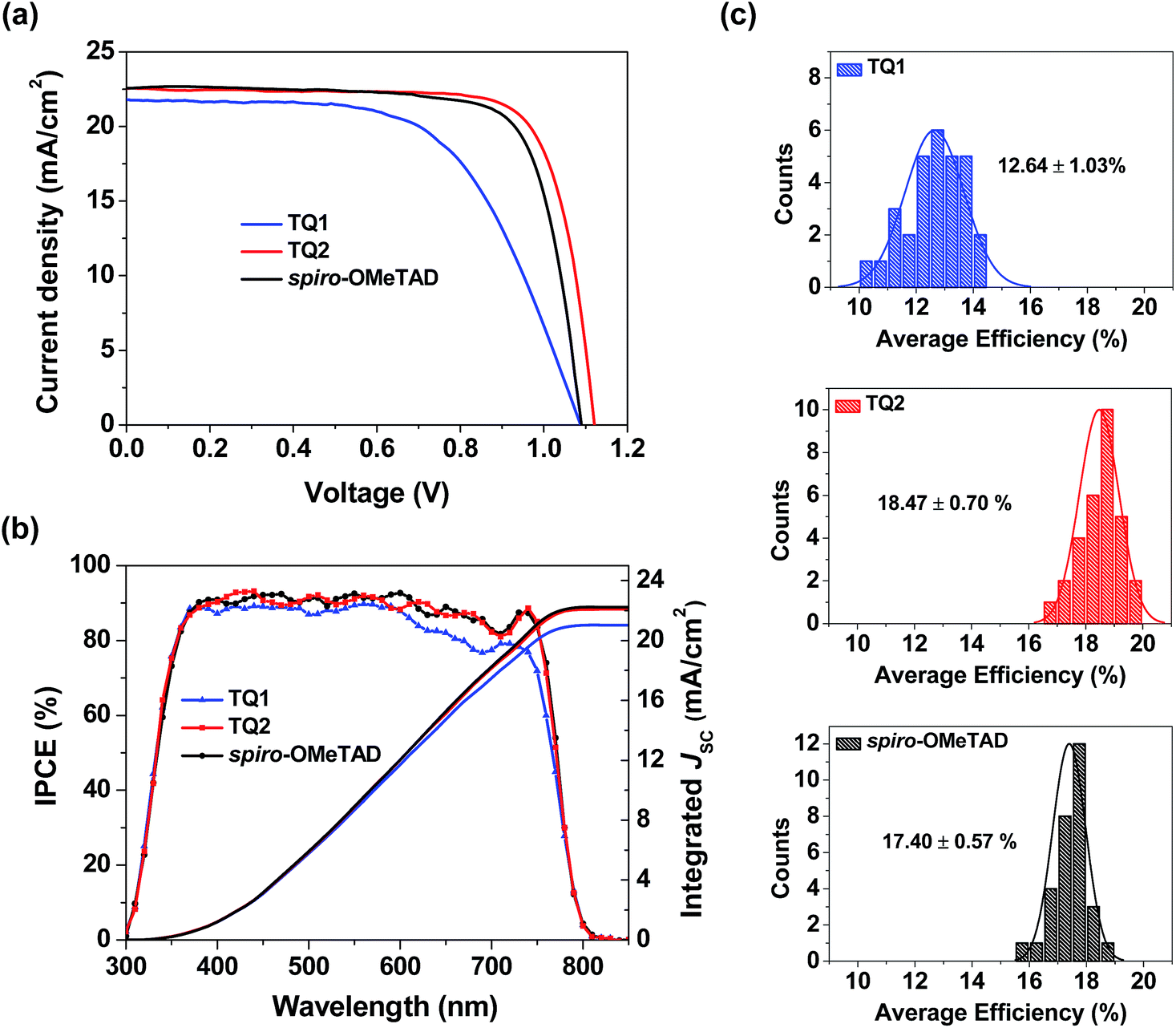
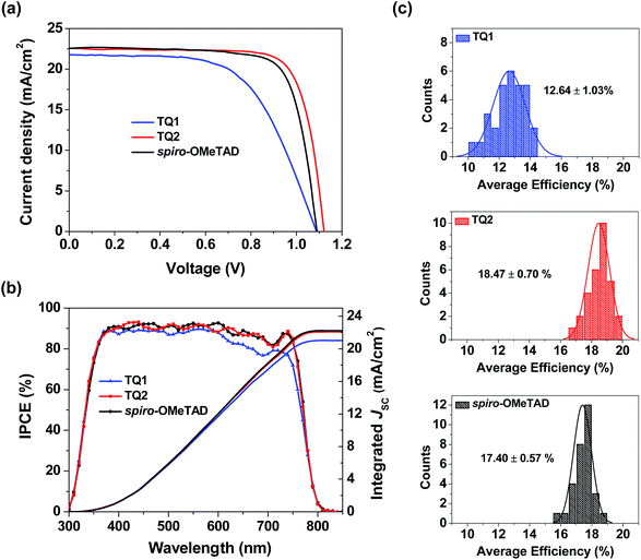
Perovskite solar cells were fabricated with a device configuration of glass/fluorine doped tin oxide (FTO)/compact TiO2 layer/mesoporous TiO2 layer/CH3NH3PbI3/HTM/Au, where the HTM is TQ1 or TQ2, or spiro-OMeTAD as a reference. Fig. S4 in the ESI† shows the cross section SEM images of corresponding devices, and the thickness of the TQ1 and TQ2 based hole-transporting layer is 90–100 nm. Fig. 4a displays the current density–voltage (J–V) curves for the best performing devices of each HTM, and the corresponding photovoltaic parameters are listed in Table 2. The J–V data were recorded with a voltage step of 10 mV and a delay time of 100 ms. The forward and reverse scanning J–V curves are almost identical under these measurement conditions, indicating a negligible hysteresis effect. The device based on TQ1 exhibits a moderate PCE of 14.27%, with a Voc of 1.09 V, a short-circuit current density (Jsc) of 21.79 mA cm−2 and a fill factor (FF) of 60.16%. In comparison, the TQ2 based cell shows a significantly improved PCE of 19.62% with a Voc of 1.12 V, a Jsc of 22.55 mA cm−2, and a FF of 77.67%. Under the similar fabrication conditions, the reference device using spiro-OMeTAD as the HTM shows a PCE of 18.54% with a Jsc of 22.58 mA cm−2, a Voc of 1.09 V and a FF of 75.32%. The steady state power output as a function of time was measured at a bias voltage of 0.77, 0.94, and 0.90 V for the devices based on TQ1, TQ2, and spiro-OMeTAD respectively. As shown in Fig. S5 in the ESI†, all of these devices can exhibit a stabilized PCE similar to the J–V measurements for over 500 s. Moreover, the operation stability of these devices was evaluated by exposing them to continuous one sun illumination with a bias near their maximum power point under controlled environmental conditions (relative humidity of 30% and temperature of 25 °C) for 100 hours. As shown in Fig. S6 in the ESI,† the PCE of the spiro-OMeTAD based device decreased to 64%. By contrast, the TQ1 and TQ2 based devices can maintain 70% and 86% of the initial value, respectively. As the other materials and fabrication conditions of the devices are the same, the improved device stability can be highly related to the HTM layer. Except for the intrinsically high stability of the D–A–D structured molecular HTMs, their uniform thin film morphology ensures a full surface coverage, thus effectively protecting the underneath perovskite layer in devices. The statistical data of the efficiency of perovskite solar cell devices employing the two new HTMs and spiro-OMeTAD are shown in Fig. 4c. Each histogram is based on 30 devices, giving average PCE values of 12.64, 18.47, and 17.40% for TQ1, TQ2, and spiro-OMeTAD, respectively. The average hysteresis indices are 6.10%, 2.56%, and 3.32% for devices based on TQ1, TQ2, and spiro-OMeTAD respectively. Unprecedentedly, such a simple and low-cost HTM (TQ2) outperforms the spiro-OMeTAD in terms of photovoltaic performance, with major improvement in the Voc parameter. These results indicate that the development of new and more suitable HTMs is a feasible way for further advancing the performance of PSCs. It is interesting to observe such a significant performance difference in TQ1 and TQ2 based devices, as their molecular structures only differ in the substituent of the quinoxaline core. The difference in Jsc was studied using the incident photon-to-current conversion efficiency (IPCE) spectrum as shown in Fig. 4b. The integrated current densities from the IPCE spectra were 21.02, 22.09, and 22.11 mA cm−2 for TQ1, TQ2, and spiro-OMeTAD, respectively, which are in good agreement with the Jsc values obtained from J–V curves measured under a AM 1.5 solar simulator. It is noticeable that the IPCE value for the TQ2 based device reached 90% in a wide wavelength range from 350 to 750 nm, well overlapped with that of spiro-OMeTAD, while the IPCE plateau of the TQ1 based device is lower across the whole range. Meanwhile, the Voc of TQ2 based devices is higher than those of TQ1 and spiro-OMeTAD based solar cells. Considering that all other components except for the HTM layer in the PSC devices were identical, the difference revealed in the photovoltaic performance must be related to the HTM properties, such as interfacial hole extraction and collection efficiency.
 |
| | Fig. 4 (a) The J–V curves for the best-performing devices using TQ1, TQ2, and spiro-OMeTAD as HTMs. (b) IPCE spectra of the solar cell devices based on different HTMs. (c) Statistical distribution in efficiencies of the perovskite solar cells fabricated with TQ1, TQ2, and spiro-OMeTAD as the HTM, respectively. | |
Table 2 Photovoltaic parameters for the best-performing devices based on TQ1, TQ2, and spiro-OMeTAD
| HTM |
Scan direction |
J
sc [mA cm−2] |
J
sc
[mA cm−2] |
V
oc [V] |
FF [%] |
PCE [%] |
|
The integrated current density from the IPCE spectra.
|
|
TQ1
|
Forward |
21.64 |
21.02 |
1.07 |
57.97 |
13.45 |
| Reverse |
21.79 |
1.09 |
60.16 |
14.27 |
|
TQ2
|
Forward |
22.52 |
22.09 |
1.11 |
76.80 |
19.20 |
| Reverse |
22.55 |
1.12 |
77.67 |
19.62 |
| Spiro-OMeTAD |
Forward |
22.50 |
22.11 |
1.08 |
73.96 |
17.97 |
| Reverse |
22.58 |
1.09 |
75.32 |
18.54 |
Hole extraction and conduction studies
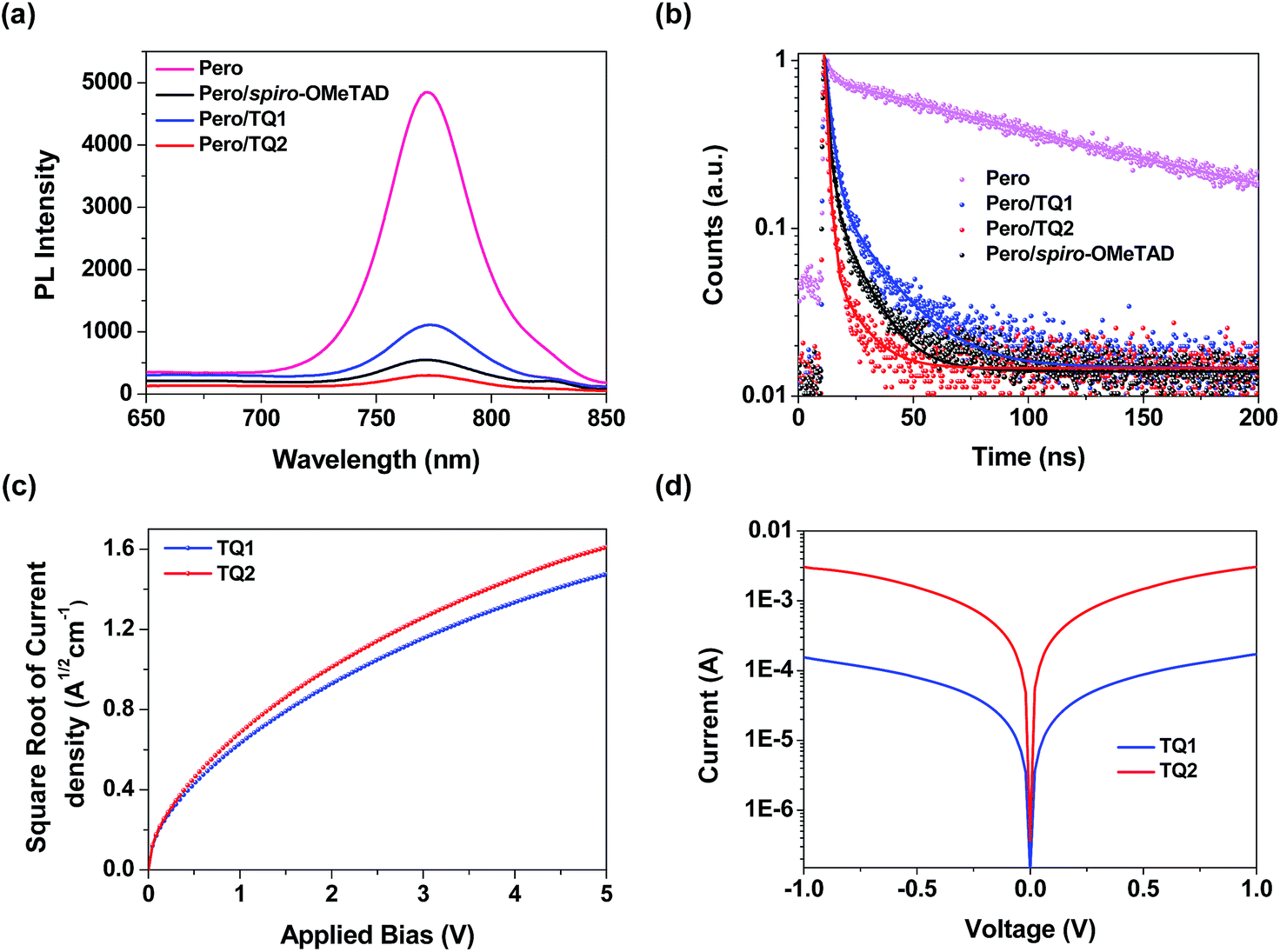
As mentioned above, both TQ1 and TQ2 can form continuous thin films with full coverage on the top of the perovskite layer (Fig. 3 and S3 in the ESI†). Their comparable thin film formation capability indicates that the large difference in photovoltaic performance shouldn't be related to the morphological issues, such as pinholes that can lead to direct contact between the perovskite and the metal electrode.42,43 To understand the photovoltaic difference caused by the HTMs, we further explored the hole extraction and transportation properties of the two new HTMs. The hole extraction capabilities of HTMs were investigated by using steady-state and time-resolved photoluminescence (PL) measurements. Fig. 5a displays the steady-state PL spectra of the MAPbI3 perovskite films without or with capping different HTMs. Upon excitation at 460 nm, a broad PL band of the perovskite film is observed to be centered at 770 nm. While all the bilayers show a dramatic quenching of PL with respect to the pristine perovskite, the perovskite/TQ2 bilayer shows a larger degree of PL quenching in all three cases. Fig. 5b shows the comparison of the time resolved PL decay at 770 nm. The pristine perovskite film shows a long-living decay that can be fitted with a two-component exponential decay model (τ1 = 4.3 ns, τ2 = 118.1 ns, τavg = 117.3 ns, see Table S5 in the ESI†). By the same fitting model, the perovskite films covered with different HTMs showed greatly shortened PL lifetime. The TQ1 coated perovskite film shows an average lifetime of 16.6 ns. In comparison, the TQ2 coated perovskite film exhibits much shorter PL lifetime (τavg = 3.4 ns), which is even much shorter than that of spiro-OMeTAD (τavg = 9.3 ns). These results indicate that TQ2 has a higher hole extraction capability with respect to TQ1, and this improved hole extraction of TQ2 might be related to the presence of the thiophene unit, which was reported to have a strong interaction with Pb2+ at the surface of perovskite.35
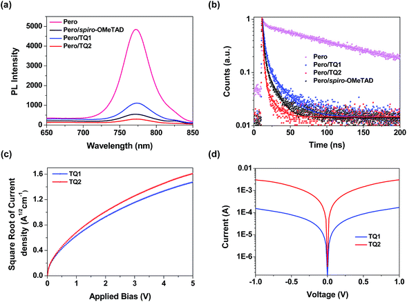 |
| | Fig. 5 (a) Steady-state PL spectra of the MAPbI3 perovskite films with or without capping different HTMs. (b) Time resolved photoluminescence decay at 770 nm for the pristine perovskite film and the perovskite films capping different HTMs. (c) The space-charge-limited-current (SCLC) measurements of hole only devices with the configuration of ITO/PEDOT:PSS/HTM/Au. (d) The conductivity measurements of TQ1 and TQ2. | |
Beside the hole extraction, the hole transportation properties of the HTM layer also play an important role in the device performance.44 The hole mobility of TQ1 and TQ2 was evaluated by the space-charge-limited current (SCLC) method.45Fig. 5c shows the fitted current density–voltage (J–V) curves, and the hole mobility values of TQ1 and TQ2 were calculated to be 9.45 × 10⁻⁵ and 2.29 × 10⁻⁴ cm2 V−1 s−1, respectively. The slightly higher hole mobility of TQ2 relative to TQ1 suggests a faster hole collection after the interfacial extraction. Moreover, by using an established method,46 the conductivity of the TQ2 based thin film with appropriate doping are estimated to be 9.19 × 10⁻⁴ S cm−1, which is one magnitude higher than that of TQ1 (6.58 × 10⁻⁵ S cm−1). In comparison, the reported hole mobility and conductivity of spiro-OMeTAD are 5.31 × 10⁻⁵ cm2 V−1 s−1 and 8.67 × 10⁻⁵ S cm−1, respectively.47 These results indicate that the intermolecular charge transport of the new HTMs was remarkably affected by the substituents on the core unit.
Insight into charge transport by single crystal analysis
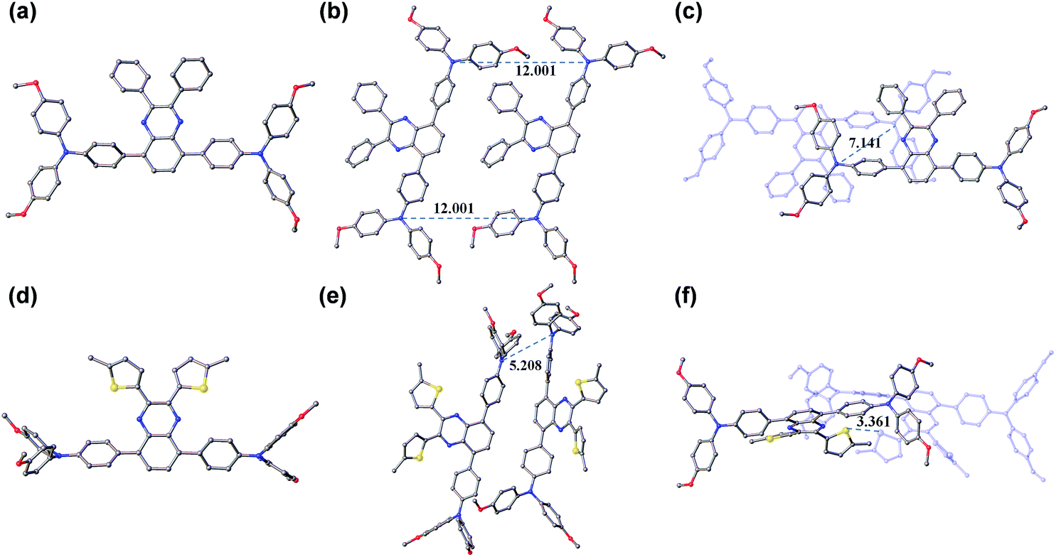
Obviously, the substituent related charge transport should have originated from their difference in molecular conformations as well as stacks in the solid state. In this regard, we tried to grow single crystals of TQ1 and TQ2, and fortunately millimeter-sized single-crystals for both materials have been obtained by the simple liquid diffusion method (CH2Cl2 and CH3OH). The ground-state geometric structure of TQ1 (triclinic, P![[1 with combining macron]](https://www.rsc.org/images/entities/char_0031_0304.gif) space group, CCDC No. 1823702, Table S3 in the ESI†) and TQ2 (orthorhombic, Pna21 space group, CCDC No. 1823703, Table S4 in the ESI†) was refined by X-ray crystallography using their single crystals, and their conformations and molecular stacks are shown in Fig. 6. We can find that the substituent groups on the quinoxaline core unit significantly affect the twisting of the triphenylamine terminals as well as the molecular stacking motif. In the case of phenyl substitution (TQ1), the peripheral phenyls of the propeller-like triphenylamine groups are almost parallel with the quinoxaline plane. In contrast, these peripheral phenyls in TQ2 are prone to be perpendicular with the quinoxaline plane, resulting in a three dimensional molecular conformation with higher steric hindrance. Moreover, three conformational isomers can be identified for TQ2 due to the slight rotation of the MeOTPA and thiophene units (Fig. S7 in the ESI†), while only one conformation was found for TQ1. Therefore, the molecular packing in the crystal structure of TQ2 is relatively more complex with respect to that of TQ1 (Fig. S8 in the ESI†). In organic HTMs, the charge transport occurs primarily via intermolecular charge hopping between adjacent molecules.9,48 As is well known, the holes are mainly delocalized on the triphenylamine units because they are the redox centers in the HTM molecule. Therefore, the average distance between the triphenylamine units of adjacent molecules is a critical parameter that can affect the charge transport properties of TQ1 and TQ2. In the TQ1 stack, the in plane and layer-to-layer distance between adjacent triphenylamine cores are 12.001 and 7.141 Å, respectively (Fig. 6b and c), while the closest triphenylamine cores in the TQ2 stack have a much smaller distance of 5.208 Å (Fig. 6e). The more tight packing of triphenylamine units is undoubtedly beneficial to the hole hopping. By carefully analyzing the molecular stacking of TQ2, we found that the thiophene units play an important role in reducing the intermolecular distance owing to the presence of strong S–S (Fig. 6f) and S–π interactions (Fig. S9 in the ESI†). Thus, incorporation of suitable substituents on the quinoxaline core unit is quite important for finely modulating the molecular stacking and enhancing the charge transporting properties of new HTMs.
space group, CCDC No. 1823702, Table S3 in the ESI†) and TQ2 (orthorhombic, Pna21 space group, CCDC No. 1823703, Table S4 in the ESI†) was refined by X-ray crystallography using their single crystals, and their conformations and molecular stacks are shown in Fig. 6. We can find that the substituent groups on the quinoxaline core unit significantly affect the twisting of the triphenylamine terminals as well as the molecular stacking motif. In the case of phenyl substitution (TQ1), the peripheral phenyls of the propeller-like triphenylamine groups are almost parallel with the quinoxaline plane. In contrast, these peripheral phenyls in TQ2 are prone to be perpendicular with the quinoxaline plane, resulting in a three dimensional molecular conformation with higher steric hindrance. Moreover, three conformational isomers can be identified for TQ2 due to the slight rotation of the MeOTPA and thiophene units (Fig. S7 in the ESI†), while only one conformation was found for TQ1. Therefore, the molecular packing in the crystal structure of TQ2 is relatively more complex with respect to that of TQ1 (Fig. S8 in the ESI†). In organic HTMs, the charge transport occurs primarily via intermolecular charge hopping between adjacent molecules.9,48 As is well known, the holes are mainly delocalized on the triphenylamine units because they are the redox centers in the HTM molecule. Therefore, the average distance between the triphenylamine units of adjacent molecules is a critical parameter that can affect the charge transport properties of TQ1 and TQ2. In the TQ1 stack, the in plane and layer-to-layer distance between adjacent triphenylamine cores are 12.001 and 7.141 Å, respectively (Fig. 6b and c), while the closest triphenylamine cores in the TQ2 stack have a much smaller distance of 5.208 Å (Fig. 6e). The more tight packing of triphenylamine units is undoubtedly beneficial to the hole hopping. By carefully analyzing the molecular stacking of TQ2, we found that the thiophene units play an important role in reducing the intermolecular distance owing to the presence of strong S–S (Fig. 6f) and S–π interactions (Fig. S9 in the ESI†). Thus, incorporation of suitable substituents on the quinoxaline core unit is quite important for finely modulating the molecular stacking and enhancing the charge transporting properties of new HTMs.
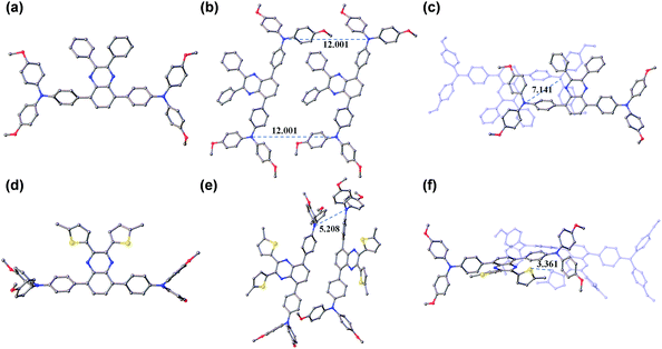 |
| | Fig. 6 Molecular conformations and stacks of TQ1 (a–c) and TQ2 (d–f). The red, yellow, blue, and grey colored atoms represent O, S, N, and C, respectively (the hydrogen atoms have been omitted for clarity). | |
Reproducible photovoltaic performance on large area devices
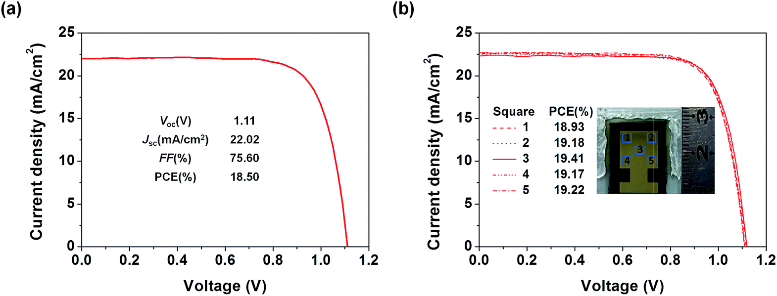
To examine the applicability of the new HTM in device scaling-up, we further employed the well-performing TQ2 to construct devices with a larger size (1.02 cm2). As expected, the optimal large area device using TQ2 as the HTM shows a promising PCE of 18.50% with a Voc of 1.11 V, a Jsc of 22.02 mA cm−2, and a FF of 75.60% (Fig. 7a). We also measured J–V curves using a small area metal mask (0.3 cm × 0.3 cm) at five different positions located in the center and at the four corners of the active area of the large size device. As shown in Fig. 7b, all of these five curves were almost identical and their PCEs showed very small variation, reflecting the superior uniformity of each active layer in the device over the square-centimeter scale. These excellent photovoltaic results in combination with cost superiority demonstrate that the new HTM TQ2 has great promise for future large-scale application.
 |
| | Fig. 7 (a) The J–V curves for the optimized large area (1.02 cm2) devices using TQ2 as the HTM. (b) J–V curves measured from five different spots with an aperture area of 0.09 cm2 selected from the large area device. | |
Conclusions
In conclusion, this study aims at the development of a low-cost alternative to the benchmark HTM of spiro-OMeTAD in PSCs for accelerating their commercial applications. We have designed and synthesized two quinoxaline based molecular HTMs (TQ1 and TQ2) featuring a D–A–D configuration, which can rationally modulate the HOMO level and improve thermal stabilities. Compared to spiro-OMeTAD, the synthetic costs of TQ1 and TQ2 are estimated to be decreased by 30 fold, the HOMO levels are downward shifted by 200 meV and the thermal decomposition temperatures are increased by 30 °C. The corresponding PSCs based on TQ2 exhibit a maximum efficiency of 19.62% (working area of 0.09 cm2), unprecedentedly outperforming that of spiro-OMeTAD (18.54%) under the same conditions. In contrast, TQ1 based devices only showed moderate efficiencies (14.27%). The differences in charge transfer/transport dynamics between TQ1 and TQ2 are explored by photoluminescence quenching and electrical measurements. The structural change of the substituents on the quinoxaline core from phenyl (TQ1) to thienyl (TQ2) not only shortens the hole extraction time (16.6 vs. 3.4 ns), but also enhances the hole mobility (9.45 × 10⁻⁵vs. 2.29 × 10⁻⁴ cm2 V−1 s−1) and conductivity (6.58 × 10⁻⁵vs. 9.19 × 10⁻⁴ S cm−1). Single crystal analysis reveals that the thienyl substituent groups in TQ2 lead to strong intermolecular S–S and S–π interactions, thus reducing the intermolecular distance and increasing the hole hopping channels to favor the charge transportation in the HTM layer. A further preliminary scaling-up test of TQ2 in the large area device (1.02 cm2) results in a promising efficiency of 18.50%. The excellent photovoltaic performance and extremely low synthetic cost indicate that the developed new HTM is promising for commercial applications.
Conflicts of interest
There are no conflicts to declare.
Acknowledgements
This work was supported by the NSFC for Creative Research Groups (21421004), Key Project (21636002), NSFC/China, the Program for Professor of Special Appointment (Eastern Scholar) at Shanghai Institutions of Higher Learning, Science and Technology Commission of Shanghai Municipality (15XD1501400, 17ZR1407400), and the Fundamental Research Funds for the Central Universities (WJ1416005, WJ1714007). The authors thank Prof. Z. Ning and T. Zhang of ShanghaiTech University for their useful discussions and technical support for device optimization.
Notes and references
- A. Kojima, K. Teshima, Y. Shirai and T. Miyasaka, J. Am. Chem. Soc., 2009, 131, 6050 CrossRef PubMed.
- H. Kim, C. Lee, J. Im, K. Lee, T. Moehl, A. Marchioro, S. Moon, R. Humphry-Baker, J. Yum, J. E. Moser, M. Grätzel and N. Park, Sci. Rep., 2012, 2, 591 CrossRef PubMed.
- I. Cho, N. J. Jeon, O. K. Kwon, D. W. Kim, E. H. Jung, J. H. Noh, J. Seo, S. I. Seok and S. Y. Park, Chem. Sci., 2017, 8, 734 RSC.
- B. Chen, X. Zheng, Y. Bai, N. P. Padture and J. Huang, Adv. Energy Mater., 2017, 7, 1602400 CrossRef.
- Q. Dong, Y. Fang, Y. Shao, P. Mulligan, J. Qiu, L. Cao and J. Huang, Science, 2015, 347, 967 CrossRef PubMed.
- W. S. Yang, B. Park, E. H. Jung, N. J. Jeon, Y. C. Kim, D. U. Lee, S. S. Shin, J. Seo, E. K. Kim, J. H. Noh and S. I. Seok, Science, 2017, 356, 1376 CrossRef PubMed.
- Z. Yu and L. Sun, Adv. Energy Mater., 2015, 5, 1500213 CrossRef.
- L. Calió, S. Kazim, M. Grätzel and S. Ahmad, Angew. Chem., Int. Ed., 2016, 55, 14522 CrossRef PubMed.
- U. Bach, D. Lupo, P. Comte, J. E. Moser, F. Weissörtel, J. Salbeck, H. Spreitzer and M. Grätzel, Nature, 1998, 395, 583 CrossRef.
- N. J. Jeon, H. G. Lee, Y. C. Kim, J. Seo, J. H. Noh, J. Lee and S. I. Seok, J. Am. Chem. Soc., 2014, 136, 7837 CrossRef PubMed.
- D. Bi, W. Tress, M. I. Dar, P. Gao, J. Luo, C. Renevier, K. Schenk, A. Abate, F. Giordano, J. Correa Baena, J. Decoppet, S. M. Zakeeruddin, M. K. Nazeeruddin, M. Grätzel and A. Hagfeldt, Sci. Adv., 2016, 2, 1501170 Search PubMed.
- J. Burschka, A. Dualeh, F. Kessler, E. Baranoff, N. Cevey-Ha, C. Yi, M. K. Nazeeruddin and M. Grätzel, J. Am. Chem. Soc., 2011, 133, 18042 CrossRef PubMed.
- Y. Hua, J. Zhang, B. Xu, P. Liu, M. Cheng, L. Kloo, E. M. J. Johansson, K. Sveinbjörnsson, K. Aitola, G. Boschloo and L. Sun, Nano Energy, 2016, 26, 108 CrossRef.
- J. M. Kadro and A. Hagfeldt, Joule, 2017, 1, 29 CrossRef.
- B. Xu, J. Zhang, Y. Hua, P. Liu, L. Wang, C. Ruan, Y. Li, G. Boschloo, E. M. J. Johansson, L. Kloo, A. Hagfeldt, A. K. Y. Jen and L. Sun, Chem, 2017, 2, 676 Search PubMed.
- K. T. Cho, S. Paek, G. Grancini, C. Roldan-Carmona, P. Gao, Y. Lee and M. K. Nazeeruddin, Energy Environ. Sci., 2017, 10, 621 RSC.
- N. J. Jeon, J. Lee, J. H. Noh, M. K. Nazeeruddin, M. Grätzel and S. I. Seok, J. Am. Chem. Soc., 2013, 135, 19087 CrossRef PubMed.
- R. A. Belisle, P. Jain, R. Prasanna, T. Leijtens and M. D. McGehee, ACS Energy Lett., 2016, 1, 556 CrossRef.
- K. Rakstys, A. Abate, M. I. Dar, P. Gao, V. Jankauskas, G. Jacopin, E. Kamarauskas, S. Kazim, S. Ahmad, M. Grätzel and M. K. Nazeeruddin, J. Am. Chem. Soc., 2015, 137, 16172 CrossRef PubMed.
- S. Paek, I. Zimmermann, P. Gao, P. Gratia, K. Rakstys, G. Grancini, M. K. Nazeeruddin, M. A. Rub, S. A. Kosa, K. A. Alamry and A. M. Asiri, Chem. Sci., 2016, 7, 6068 RSC.
- M. Zhang, G. Wang, D. Zhao, C. Huang, H. Cao and M. Chen, Chem. Sci., 2017, 8, 7807 RSC.
- H. Li, K. Fu, A. Hagfeldt, M. Grätzel, S. G. Mhaisalkar and A. C. Grimsdale, Angew. Chem., Int. Ed., 2014, 53, 4085 CrossRef PubMed.
- B. Xu, D. Bi, Y. Hua, P. Liu, M. Cheng, M. Gratzel, L. Kloo, A. Hagfeldt and L. Sun, Energy Environ. Sci., 2016, 9, 873 RSC.
- S. Paek, I. Zimmermann, P. Gao, P. Gratia, K. Rakstys, G. Grancini, M. K. Nazeeruddin, M. A. Rub, S. A. Kosa, K. A. Alamry and A. M. Asiri, Chem. Sci., 2016, 7, 6068 RSC.
- Y. Wu, W. Zhu, S. M. Zakeeruddin and M. Grätzel, ACS Appl. Mater. Interfaces, 2015, 7, 9307 CrossRef PubMed.
- W. Zhu, Y. Wu, S. Wang, W. Li, X. Li, J. Chen, Z. Wang and H. Tian, Adv. Funct. Mater., 2011, 21, 756 CrossRef.
- Y. Wu and W. Zhu, Chem. Soc. Rev., 2013, 42, 2039 RSC.
- Z. A. Li, Z. Zhu, C. Chueh, S. B. Jo, J. Luo, S. Jang and A. K. Y. Jen, J. Am. Chem. Soc., 2016, 138, 11833 CrossRef PubMed.
- H. Choi, S. Park, M. Kang and J. Ko, Chem. Commun., 2015, 51, 15506 RSC.
- F. Wu, Y. Ji, R. Wang, Y. Shan and L. Zhu, Dyes Pigm., 2017, 143, 356 CrossRef.
- H. Choi, H. M. Ko and J. Ko, Dyes Pigm., 2016, 126, 179 CrossRef.
- K. Pei, Y. Wu, A. Islam, Q. Zhang, L. Han, H. Tian and W. Zhu, ACS Appl. Mater. Interfaces, 2013, 5, 4986 CrossRef PubMed.
- M. Liu, Y. Gao, Y. Zhang, Z. Liu and L. Zhao, Polym. Chem., 2017, 8, 4613 RSC.
- Y. Chen, Y. Ling, L. Ding, C. Xiang and G. Zhou, J. Mater. Chem. C, 2016, 4, 8496 RSC.
- M. Saliba, S. Orlandi, T. Matsui, S. Aghazada, M. Cavazzini, J. Correa-Baena, P. Gao, R. Scopelliti, E. Mosconi, K. Dahmen, F. De Angelis, A. Abate, A. Hagfeldt, G. Pozzi, M. Graetzel and M. K. Nazeeruddin, Nat. Energy, 2016, 1, 15017 CrossRef.
- M. L. Petrus, T. Bein, T. J. Dingemans and P. Docampo, J. Mater. Chem. A, 2015, 3, 12159 RSC.
- Y. Hua, B. Xu, P. Liu, H. Chen, H. Tian, M. Cheng, L. Kloo and L. Sun, Chem. Sci., 2016, 7, 2633 RSC.
- A. J. Zucchero, P. L. McGrier and U. H. F. Bunz, Acc. Chem. Res., 2010, 43, 397 CrossRef PubMed.
- R. Grisorio, B. Roose, S. Colella, A. Listorti, G. P. Suranna and A. Abate, ACS Energy Lett., 2017, 2, 1029 CrossRef.
- S. Ryu, J. H. Noh, N. J. Jeon, Y. Chan Kim, W. S. Yang, J. Seo and S. I. Seok, Energy Environ. Sci., 2014, 7, 2614 RSC.
- S. Park, J. H. Heo, C. H. Cheon, H. Kim, S. H. Im and H. J. Son, J. Mater. Chem. A, 2015, 3, 24215 RSC.
- L. K. Ono, S. R. Raga, M. Remeika, A. J. Winchester, A. Gabe and Y. Qi, J. Mater. Chem. A, 2015, 3, 15451 RSC.
- C. Besleaga, L. E. Abramiuc, V. Stancu, A. G. Tomulescu, M. Sima, L. Trinca, N. Plugaru, L. Pintilie, G. A. Nemnes, M. Iliescu, H. G. Svavarsson, A. Manolescu and I. Pintilie, J. Phys. Chem. Lett., 2016, 7, 5168 CrossRef PubMed.
- X. Jiang, Z. Yu, J. Lai, Y. Zhang, N. Lei, D. Wang and L. Sun, Sci. China: Chem., 2017, 60, 423 CrossRef.
- Y. Wang, Z. Zhu, C. Chueh, A. K. Y. Jen and Y. Chi, Adv. Energy Mater., 2017, 7, 1700823 CrossRef.
- Y. Li, Z. Xu, S. Zhao, B. Qiao, D. Huang, L. Zhao, J. Zhao, P. Wang, Y. Zhu, X. Li, X. Liu and X. Xu, Small, 2016, 12, 4902 CrossRef PubMed.
- B. Xu, E. Sheibani, P. Liu, J. Zhang, H. Tian, N. Vlachopoulos, G. Boschloo, L. Kloo, A. Hagfeldt and L. Sun, Adv. Mater., 2014, 26, 6629 CrossRef PubMed.
- B. Xu, H. Tian, L. Lin, D. Qian, H. Chen, J. Zhang, N. Vlachopoulos, G. Boschloo, Y. Luo, F. Zhang, A. Hagfeldt and L. Sun, Adv. Energy Mater., 2015, 5, 1401185 CrossRef.
Footnote |
| † Electronic supplementary information (ESI) available. CCDC 1823702 and 1823703. For ESI and crystallographic data in CIF or other electronic format see DOI: 10.1039/c8sc00731d |
|
| This journal is © The Royal Society of Chemistry 2018 |
Click here to see how this site uses Cookies. View our privacy policy here. 
 Open Access Article
 This Open Access Article is licensed under a Creative Commons Attribution-Non Commercial 3.0 Unported Licence
 *
*