 Open Access Article
A combined experimental and computational study on the reaction of fluoroarenes with Mg–Mg, Mg–Zn, Mg–Al and Al–Zn bonds†
Clare
Bakewell
,
Bryan J.
Ward
,
Andrew J. P.
White
and
Mark R.
Crimmin
 *
*
Department of Chemistry, Imperial College London, South Kensington, London, SW7 2AZ, UK. E-mail: m.crimmin@imperial.ac.uk
First published on 23rd January 2018
Abstract
Through a combined experimental and computational (DFT) approach, the reaction mechanism of the addition of fluoroarenes to Mg–Mg bonds has been determined as a concerted SNAr-like pathway in which one Mg centre acts as a nucleophile and the other an electrophile. The experimentally determined Gibbs activation energy for the addition of C6F6 to a Mg–Mg bond of a molecular complex, ΔG‡298 K(experiment) = 21.3 kcal mol−1 is modelled by DFT with the ωB97X functional, ΔG‡298 K(DFT) = 25.7 kcal mol−1. The transition state for C–F activation involves a polarisation of the Mg–Mg bond and significant negative charge localisation on the fluoroarene moiety. This transition state is augmented by stabilising closed-shell Mg⋯Fortho interactions that, in combination with the known trends in C–F and C–M bond strengths in fluoroarenes, provide an explanation for the experimentally determined preference for C–F bond activation to occur at sites flanked by ortho-fluorine atoms. The effect of modification of both the ligand coordination sphere and the nature and polarity of the M–M bond (M = Mg, Zn, Al) on C–F activation has been investigated. A series of highly novel β-diketiminate stabilised complexes containing Zn–Mg, Zn–Zn–Zn, Zn–Al and Mg–Al bonds has been prepared, including the first crystallographic characterisation of a Mg–Al bond. Reactions of these new M–M containing complexes with perfluoroarenes were conducted and modelled by DFT. C–F bond activation is dictated by the steric accessibility, and not the polarity, of the M–M bond. The more open coordination complexes lead to enhanced Mg⋯Fortho interactions which in turn lower the energy of the transition states for C–F bond activation.
Introduction
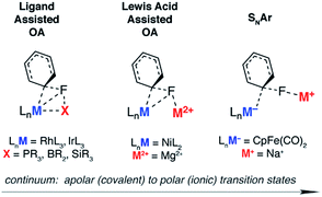
The activation of strong carbon–fluorine bonds remains a key academic and industrial challenge that is motivated by the prevalence of fluorine-containing molecules in the pharmaceutical, agricultural and materials industries. Recent advances have focused on the functionalisation of fluoroarenes, with aim of making synthetically useful building blocks.1,2 In particular, C–F activation and subsequent borylation has been reported to occur catalytically using a range of late transition metal catalysts.3–13The activation of aromatic sp2 C–F bonds with transition metal complexes is known to proceed by several mechanisms, most common of which are oxidative addition (OA) and nucleophilic aromatic substitution (SNAr).14–16 Oxidative addition is typically observed with 14- or 16-electron complexes of the form ML2 (M = Ni, Pd, Pt) or ML3X (M = Rh, Ir), where higher oxidation states are easily accessible.
The concept of ligand-assisted C–F bond activation was introduced to rationalise experimentally observed fluorophosphines, formed during the reaction of perfluoroarenes with group 9 and 10 transition metal phosphine complexes.17,18 Originally reported by Milstein in the early 1990s, the reaction of C6F6 with [(Et3P)3IrMe] forms [(Et3P)2(FEt2P)IrC6F5] along with ethene and methane. Density functional calculations were used to substantiate a pathway that occurs by 1,2-addition of the C–F to the Ir–P bond: nucleophilic attack of the electron-rich metal on the fluorocarbon occurs with simultaneous activation, and trapping, of the fluoride by the phosphine. The concept has been expanded to boryl-assisted C–F activation using a [(Et3P)3RhBpin] complex and the mechanism used to explain the experimentally observed activation of pentafluoropyridine at the 2-position (Fig. 1 – ligand assisted OA).3
Lewis acid-assisted C–F bond activation, has been explored in a detailed experimental and theoretical study by Nakamura and co-workers. This mechanism is conceptually related to the ligand-assisted pathway but differs in that the Lewis acidic and nucleophilic metal centers are not directly bound to one another (Fig. 1 – Lewis acid assisted OA). Kumada–Tamao–Corriu cross-coupling reactions between aryl fluorides and Grignard reagents can be catalysed by [Ni(acac)2].19 The use of a dinucleating hydroxyphosphine ligand leads to an active catalyst, which operates through a cooperative push–pull mechanism. The nickel and magnesium centers act as electron donors and acceptors respectively, facilitating C–F bond activation.
Nucleophilic mechanisms have been invoked for coordinatively saturated anionic 18-electron complexes, and are facilitated by the highly polar C–F bond. For example, C–F activation of fluoroarenes and fluoroalkenes using the Fp− (cyclopentadienyliron dicarbonyl) anion is proposed to occur by nucleophilic aromatic substitution (Fig. 1 – SNAr) and nucleophilic vinylic substitution respectively.20,21 While the relative rates of reactions are consistent with the known nucleophilicity scale20 of anionic transition metal carbonyl complexes,22,23 the true degree of charge separation in the proposed transition state for C–F bond activation remains a point of debate.24 Related nucleophilic anionic intermediates, formed via deprotonation of [Cp*M(PMe3)H2] (M = Rh, Ir) are also postulated to be the active species in C–F bond activation reactions.25,26
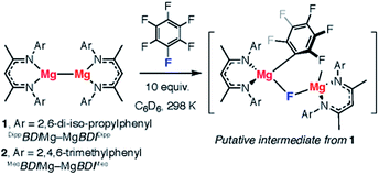
We recently reported the C–F bond activation of a series of perfluorinated and partially fluorinated arenes, using the low valent Mg(I) species 1 (Fig. 2).27,28
The reaction results in the formation of a new Mg–C bond and a new Mg–F bond and may be considered as a homogeneous equivalent to Grignard formation. The new organometallic complexes have potential to be used as fluorinated building blocks in synthesis.29 Initial mechanistic investigations provided support for a concerted two-electron reaction pathway, with no radical intermediates detected through trapping experiments. A plausible transition state for this reaction involves the 1,2-addition of the C–F bond across the apolar Mg–Mg bond.
Herein, we report a joint experimental and computational analysis of the carbon–fluorine bond activation of fluorinated arenes using low-valent complexes which contain M–M bonds (M = Mg, Zn, Al). We provide strong evidence for the proposed concerted pathway and a transition state reminiscent of those represented in Fig. 1 that involves dual nucleophilic and electrophilic sites that polarise and activate the C–F bond. We introduce additional experiments and prepare new M–M complexes in order to interrogate the key transition state for C–F activation. Specifically, the effects of steric accessibility and M–M bond polarity on reaction rates are reported.
Results
Concerted addition of C6F6 to 1
The reaction mechanisms reported herein were studied by DFT using the Gaussian 09 suite (revision D.01)30 and optimisations employed the ωB97X functional.31 Mg and Zn centers were described with Stuttgart SDDAll RECPs and associated basis sets whereas 6-31G** basis sets was used for all other atoms.32–36 Free energies are corrected for both benzene solvent using the Polarisable Continuum Model (PCM) approach and dispersion effects using ωB97X-D.37,38The potential energy surface for the reaction of C6F6 with 1 is presented in Fig. 3a. C–F bond activation is initiated upon weak coordination of C6F6 to the ligand sphere of 1 to create the encounter complex, Int-A. Substrate association to 1 occurs by a network of non-covalent interactions (e.g. C–H⋯F, C–H⋯π, π⋯π) which although individually weak contribute to a modest binding enthalpy of ΔHo = −9.2 kcal mol−1 (Fig. S27†).
The increased ordering of the system is, however entropically unfavourable and thus fluoroarene binding is slightly endergonic (ΔGo = 1.1 kcal mol−1). The ligands in Int-A are oriented perpendicular to one another and rotation around the Mg–Mg bond is required to access the more reactive conformer Int-A′. Int-A′ contains a reactive pocket and a sterically accessible Mg–Mg bond. C–F bond activation occurs via the concerted transition state TS-1 (ΔG‡298 K = 25.7 kcal mol−1). Decay from TS-1 leads to the C–F activation product Int-B in which a newly formed Mg–C bond and bridging Mg–F–Mg bond contribute to a 6-membered ring structure. Overall C–F bond activation is extremely exergonic (ΔGorxn = −112.2 kcal mol−1).
An Eyring analysis on the reaction of 1 with C6F6 under pseudo first-order conditions, conducted over the temperature range 258–288 K, yielded activation parameters ΔH‡ = 10.8 kcal mol−1 and ΔS‡ = −35 cal K−1 mol−1 (Fig. 3b and c). The experimental negative activation entropy is consistent with a highly ordered transition state, while the activation enthalpy is suggestive of a transition state with only minimal bond making and breaking having occurred. The Gibbs activation energy ΔG‡298 K = 21.3 kcal mol−1 matches reasonably well with that determined from DFT, ΔG‡298 K = 25.7 kcal mol−1.39
The transition state for C–F bond activation
The calculated TS-1 is suggestive of an asynchronous concerted process: considerable Mg–C bond formation has occurred before any significant C–F bond breaking (Fig. 4). Formally, the transition state involves the concerted oxidative addition of the C–F bond to the Mg–Mg bond. Related pathways have been calculated for the addition of C–F bonds of fluoroarenes to single-site Al(I) and Si(II) centres.40–42 The bond lengths and angles around the ipso-carbon (Fig. S28a†), along with the charge distribution about the aromatic ring, however are consistent with an SNAr-like mechanism for C–F activation with one Mg center acting as a nucleophile, attacking the aromatic ring, while the other acts as an electrophile, binding to and polarising the breaking C–F bond.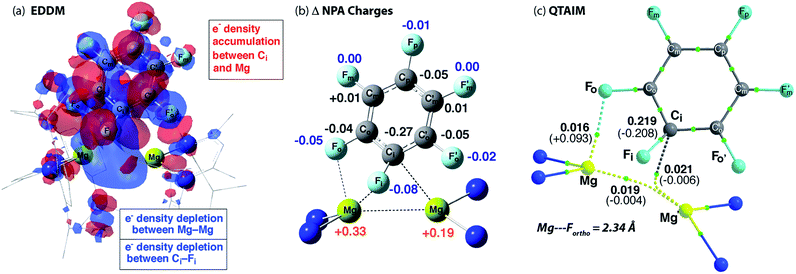 | ||
| Fig. 4 (a) Energy density difference map (EDDM) for TS-1, (b) the change (Δ) in NPA charges from Int-A′ to TS-1 and (c) QTAIM data on TS-1: ρ(r) values in bold, ∇2ρ values in parentheses. Full QTAIM for TS-1 in Fig. S28b.† | ||
An electron density difference map illustrates the depletion of electron density between the breaking C–F and Mg–Mg bonds along with the simultaneous accumulation of electron density between Mg and C at the forming Mg–C bond (Fig. 4a). Electron density accumulation also occurs at both ortho- and para-carbons of the fluoroarene. The electron density redistribution in TS-1 is mirrored by the NBO analysis showing the difference in the NPA charges between TS-1 and Int-A′ (Fig. 4b). The loss of electron density at the Mg centers (Δ = +0.52 e) is redistributed to the fluoroarene ring (Δ = −0.53 e) and approximately half of the redistributed electron density is localised at ipso-carbon (Δ = −0.27 e).
The effect of functional group substitution on the reaction rates of concerted SNAr pathways is well understood: stabilisation of the negative charge on aromatic ring through inductive and mesomeric effects leads to an increase in reaction rate. Rate constants were measured for the reaction of 1 with a series of fluoroarenes of the form C6F5R. The group para- to the breaking C–F bond was varied and rate constants were measured under pseudo first-order conditions (Table S1†). Broadly the relative rate increases with stabilisation of negative charge on the ipso-carbon, leading to the general reactivity trend: R = CF3 > F > C6F5 > CH3.
Importance of secondary Mg⋯Fortho interactions in the TS for C–F activation
In addition to the expected Mg⋯Fipso interaction derived from the breaking C–F bond, there is a significant Mg⋯Fortho interaction in TS-1 that is retained in Int-B. The presence of a strong Mg⋯Fortho interaction is evidenced by a short Mg⋯Fortho distance (2.34 Å). The QTAIM molecular graph of TS-1 (Fig. 4c) identifies the presence of a bond critical point (BCP) between Mg and Fortho. The attributes of the BCP (small ρ(r), small positive ∇2ρ) are indicative of a weak, closed shell interaction. The DFT prediction of this secondary Mg⋯F interaction is particularly noteworthy, as experimentally the addition of C–F bonds of fluoroarenes to the Mg–Mg bond of 1 always proceeds to give regioisomers in which at least one ortho-fluorine atom is adjacent to the C–F bond that breaks.The effect of the position of fluorine substitution and the importance of the secondary Mg⋯Fortho interaction on the C–F bond cleavage transition state was interrogated by calculating the pathway for the addition of C6F5H to 1. Fig. 5 compares the change in Gibbs activation energy for the regioisomeric transition states (relative to TS-1). DFT calculations predict that substitution at positions X2 and X3 should lead to lowest energy transition states. Experimentally, regioisomeric products of C–F activation of both these positions of C6F5H are observed.27
Substitution (of fluorine for hydrogen) at X1 is highly disfavored and removes the ortho-fluorine substituent that anchors the substrate in the C–F bond activation TS (ΔΔG = +5.1 kcal mol−1). For comparison, X5 is not involved in appreciable Mg⋯Fortho bonding in the transition state and substitution here only raises the TS by +1.8 kcal mol−1. Substitution at X4 also raises the energy of the C–F activation TS (ΔΔG = +2.8 kcal mol−1). This position is expected to exert a secondary influence on the Mg⋯Fortho binding energy. The fluorine atom in position X4 is a weak π-donor and will increase the electron density on X1. Replacing X4 with a hydrogen atom will remove this effect diminishing the electrostatic interaction between Mg and Fortho.
The importance of the ortho-fluorine substituents was further exemplified by calculating the transition state for C–F bond activation of 1,3-C6F4H2 in which both positions ortho- to the breaking C–F bond are occupied by hydrogen atoms (Fig. S30†). The absence of any Mg⋯Fortho anchor results in a reorganisation of the TS to a conformer in which the breaking C–F bond is parallel with the Mg–Mg bond (ΔΔG = +9.5 kcal mol−1 relative to TS-1). The geometry of this reorganised TS is consistent with that reported for the addition of CO2 to 1 reported by Maron and co-workers.43
Effect of sterics on the TS for C–F activation
A number of analogues of 1 are known. These include a series of β-diketiminate complexes which differ in the steric profile of the flanking aromatic groups on the ligand. Consideration of the data above leads to the obvious question, what are the effects of sterics in C–F bond activation by addition to a Mg–Mg bond?The potential energy surface for C–F bond activation of C6F6 by 2 (MesBDIMg–MgBDIMes) was calculated and compared to that of 1 (DippBDIMg–MgBDIDipp). The reduced steric bulk of the mesityl substituents results in greater access to the Mg–Mg bond. Consequently, the substrate coordinates to Mg in 2 through a short Mg⋯F interaction (2.76 Å) to give Int-C. Overall, the formation of Int-C is facile (ΔG = 0.3 kcal mol−1). Rotation about the Mg–Mg bond in Int-C gives the more reactive conformer Int-C′ which contains a stronger Mg⋯F interaction (2.66 Å) in the form of a κ1-bound fluoroarene adduct.44,45 The transition state for C–F cleavage TS-2 is located 23.0 kcal mol−1 above the reactants and leads to Int-D (Fig. 6a). Significantly TS-2 contains two Mg⋯Fortho interactions as evidenced by the short M⋯Fortho distances (Fig. S31a†) and quantified by QTAIM analysis (Fig. 6b). These electrostatic interactions undoubtedly contribute to transition state stabilisation and explain the lower energy of TS-2 relative to TS-1 (Fig. 6a).
 | ||
| Fig. 6 (a) The calculated reaction pathway for C–F activation with 2, inset shows Mg⋯Mg separation. (b) QTAIM plot of TS-2: ρ(r) values in bold, ∇2ρ values in parentheses. Full QTAIM for TS-2 in Fig. S31b.† (c) Competition experiments between 1 or 2 and fluoroarenes. | ||
Experimental data were collected to verify the hypothesis that 2 is more reactive to fluoroarenes than 1 (Fig. 6c). The reaction between 2 (0.02 M) and 10 equiv. of C6F6 in C6D6 was facile, with immediate observation of 19F NMR resonances at δ = −118.5, −157.1 and −158.3 ppm corresponding to the Mg–C6F5 moiety. A further resonance at δ = −183.3 ppm is assigned to a Mg–F by-product.46 A competition reaction between 1, 2, and C6F6, led exclusively to products derived from C–F bond activation with 2. Further experiments replacing C6F6 with 2-(2,3,4,5,6-pentafluorophenyl)-pyridine (2-Py-C6F5) again led to exclusive reaction of 2 with no evidence for the participation of 1 despite its known reaction with the same substrate. As with the analogous reaction using 1, 2 reacts with 2-Py-C6F5 at the 2-position. Both the C–F activation product 2a and the fluoride-containing by-product [{MesBDIMg}3(μ-F)3] (2b) have been characterised by single crystal X-ray diffraction, the latter complex forming a fluoride bridged trimer in the solid state.47
Effect of M–M bond polarisation on the TS for C–F activation
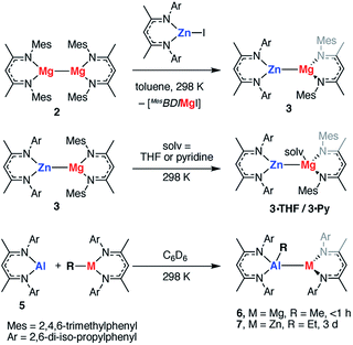
The polarisation of the Mg⋯Mg bond in TS-1 and TS-2 raises a further question: do reactions of polar M–M bonds proceed faster than apolar M–M bonds? To address this question a series of new heterobimetallic complexes with polar M–M′ bonds (M = Mg, M′ = Zn, Al; M = Zn, M′ = Al) were prepared. Complexes 3, 4, 6, 7 are novel M–M containing species, and their synthesis was inspired by recently described methods, namely metathesis,48–52 and insertion of an Al(I) reagent53–59 into metal–carbon bonds.60,61 Despite the exploitation of known methods, this represents a highly novel series of main group complexes containing metal–metal bonds, including the first example of a crystallographically characterised Mg–Al bond and rare examples of Mg–Zn, Zn–Al and Zn–Zn–Zn bonds for which there is limited precedent.Complex 3, containing a new Mg–Zn bond, was synthesised by the stoichiometric reaction of the corresponding zinc iodide with 2 (Scheme 1). The reaction occurs with concomitant formation of one equiv. of the β-diketiminate supported magnesium(II) iodide and 3 could be isolated cleanly by exploitation of the difference in solubility between the two products (54% isolated yield). Compound 3 was found to be unstable in solution, degrading slowly over time (days) to form the mixed bis-β-diketiminate complex [Mg(DippBDI)(MesBDI)] along with a black precipitate (presumed to be Zn0). Compound 3 can, however, be stored over a prolonged period of time at 238 K, as a solid or in hydrocarbon solution. This complex may be trapped by insertion of a carbodiimide (RN![[double bond, length as m-dash]](https://www.rsc.org/images/entities/char_e001.gif) C
C![[double bond, length as m-dash]](https://www.rsc.org/images/entities/char_e001.gif) NR, R = Cy, i-Pr) into the Mg–Zn bond and details of these experiments are provided in the ESI.† An analogue of 3 bearing solely mesityl substituted ligands was also prepared but could not be isolated cleanly.
NR, R = Cy, i-Pr) into the Mg–Zn bond and details of these experiments are provided in the ESI.† An analogue of 3 bearing solely mesityl substituted ligands was also prepared but could not be isolated cleanly.
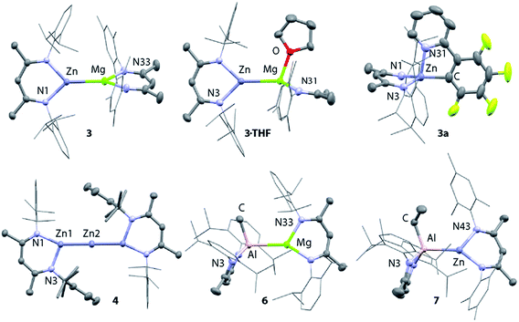
X-ray quality crystals of 3 were grown from n-hexane at 238 K. The Mg–Zn bond length in 3 is 2.5993(8) Å, which is comparable with the only two previously reported examples of complexes containing a magnesium–zinc bond (Fig. 7, Table 1).48 This value lies between the bond lengths of analogous Mg–Mg (2.8078–2.8700(9) Å) and Zn–Zn (2.3586(7)-2.3813(8) Å) β-diketiminate complexes.27,51,62–64 Comparison of the series of structures reveals that the complexes adopt a number of conformers in the solid state which differ by the dihedral angle between the two β-diketiminate planes. A low energy difference between these conformers is anticipated, as would be consistent with the small calculated energy difference between Int-A and Int-A′ (Fig. 3).
| 3 | 3·THF | 2a | 3a | 4 | 6 | 7 | |
|---|---|---|---|---|---|---|---|
| a fsr is the formal shortness ratio defined as the bond length/sum of the single bond radii (Pauling). | |||||||
| M–M | 2.5993(8) | 2.6816(8) | — | — | 2.3908(3) | 2.7687(8) | 2.4877(10) |
| fsr | 0.99 | 1.03 | — | — | 0.98 | 1.06 | 1.00 |
| M–N | 2.0243(18) | 2.0782(19) | 2.037(3) | 1.979(2) | 1.9761(18) | 2.0862(10) | 2.034(3) |
| 2.0540(19) | 2.0999(19) | 2.035(3) | 1.973(2) | 2.016(3) | 1.9739(10) | 1.933(3) | |
| M–X | — | 2.1116(18) | 2.156(4) | 1.980(3) | — | 1.9856(13) | 1.980(3) |
| X = O | X = C | X = C | X = C | X = C | |||
Addition of the coordinating solvents, THF and pyridine, to 3 led to the formation of the coordination complexes 3·THF and 3·Py, respectively. Integration of the 1H NMR spectra indicates that in both cases only one equiv. of solvent is bound (Scheme 1). This was confirmed by the X-ray structure of 3·THF, which shows one molecule of tetrahydrofuran coordinated to magnesium, whilst the zinc remains in a three-coordinate geometry (Fig. 7).
The Mg–Zn bond length of 3·THF (2.6816(8) Å) is significantly longer than that of 3, a phenomenon also observed in the di-solvated solid-state structures of 1 (where solv. = THF, pyridine, DMAP).653·THF is a loose approximation of Int-C′ (Fig. 6a) and suggests that substrate coordination to a single metal center is a feasible proposition in the pathway for C–F bond activation.
Following isolation of 3, further small amounts of bright yellow crystals were observed to form in the reaction filtrate. Single crystal X-ray diffraction revealed formation of the novel tri-zinc species, 4. Compound 4 is only the second reported example of a linear tri-zinc complex.484 is Ci symmetric and the Zn–Zn–Zn bond is linear (180°). The Zn–Zn bond length of 2.3908(3) Å is slightly longer than in the previously reported example bearing mono-dentate amide ligands. Compound 4 is iso-structural with a previously reported Zn–Hg–Zn complex.52,66
Related Mg–Al and Zn–Al complexes were also prepared. The stoichiometric reaction of 5 with magnesium and zinc alkyl complexes in C6D6 resulted in the formation of new asymmetric products, 6 and 7, respectively (Scheme 1). Deep red crystals of 6 and yellow crystals of 7 were grown from concentrated n-hexane solutions at 238 K (Fig. 7). Single crystal X-ray diffraction studies confirmed the presence of a newly formed aluminium–metal bond, which measured 2.7687(5) Å for Al–Mg and 2.488(1) Å for Al–Zn.60 The aluminium centers in 6 and 7 have a distorted tetrahedral geometry, with τ′4 values of 0.87 and 0.93, respectively. Both compounds 6 and 7 were found to be remarkably stable in solution, with no degradation observed when heated for 48 h at 353 K.67
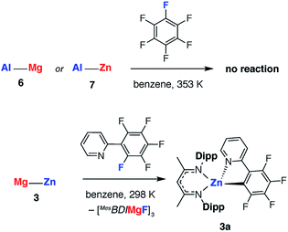
The effect of polarity on C–F activation with main group compounds containing M–M′ bonds was investigated. Reaction of the heterobimetallic species 3, 6 and 7, with fluoroarenes were conducted in hydrocarbon solution. No evidence of C–F bond activation was observed upon reaction of Mg–Al (6) or Zn–Al (7) containing compounds with a range of fluorocarbons (e.g. C6F6, C6F5H and 2-Py-C6F5) between 298 and 353 K. While 3 does react slowly with C6F6 at room temperature this reaction is competitive with decomposition of the Mg–Zn reagent.68,69 A clean reaction was observed between 3 and 2-Py-C6F5 to form the Zn complex 3a and the corresponding magnesium fluoride (Scheme 2, Fig. 7).
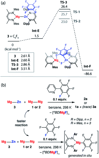
The reaction pathway for the addition of C6F6 to 3 was calculated and shown to be analogous to that described for 1. C–F bond cleavage occurs via an asymmetric transition state TS-3 (Fig. S32†) which leads to Zn–C and Mg–F bond formation and is 26.4 kcal mol−1 higher in energy than the separated reactants. Consideration of the difference in electronegativity between Mg (χp = 1.31) and Zn (χp = 1.65) explains the geometry of the transition state and the destination of the fluorine atom in the reaction. All attempts to locate a transition state that resulted in Mg–C and Zn–F bond formation led to TS-3 and it is clear that polarisation of the M–M′ bond is a key factor in determining the outcome of the reaction (Fig. 8a).
In combination, these experiments suggest that Mg–Zn, Mg–Al and Zn–Al reagents prepared herein are all less reactive toward fluoroarenes than 1 or 2. This finding was borne out by competition experiments using both C6F6 and 2-Py-C6F5. The rate of reaction of 3 with 2-Py-C6F5 is marginally slower than with 2, t1/2 = 1 h versus <0.5 h, but is significantly faster than degradation of 3. Competition experiments between 3 and 2 confirm the relative rates and led to reaction of the Mg–Mg reagents in all cases (Fig. 8b). While competition experiments between 3 and 1 also resulted in selective formation of the organomagnesium species, in this instance trace amounts of 3a are also formed. The relative reactivity is predicted by DFT calculations and TS-3 is higher in energy than both TS-2 (ΔΔG = 3.4 kcal mol−1) and TS-1 (ΔΔG = 0.7 kcal mol−1). Given the small energy difference involved, the computational methods do not result in a quantitative prediction of the reaction outcome in terms of an accurate product distribution but rather a qualitative prediction of the most reactive species. In line with these predictions, C–F bond activation by 6 and 7 are calculated to occur by concerted transition states TS-4 and TS-5 (Fig. S33†) with ΔG‡298 K of 40.0 and 65.1 kcal mol−1 respectively. While in both cases the calculations predict the formation of C–Al bonds upon C–F activation with 6 or 7, the activations barriers are prohibitively high and these reactions are not observed experimentally.
Conclusions
Sterics versus bond polarisation
Comparison of TS-1-3 and consideration of the competition experiments definitively shows that sterics are the dominant factor at play in determining the reactivity of M–M bonds toward C–F activation of fluoroarenes. Despite polarisation of the M–M bond occurring in the transition state to C–F bond cleavage, introduction of polarity into the M–M′ bond by variation of the metals, while determining the selectivity of addition, does not lead to faster rates of reaction. Moreover, blocking access to the M–M′ bond through increasing the coordination number of one of the metals from 3- to 4-coordinate (in 6 and 7) completely shuts down reactivity. These results can be rationalised based on the ease of the formation of the C–F bond activation transition state. The polar heterobimetallics (such as 3) have contracted M–M′ bonds relative to apolar ones, due to the ionic contribution to bonding, and this bond length contraction closes up the steric pocket that is required for formation of the transition state for C–F bond activation (Table S7, Fig. S34†).A thermodynamic ortho-fluorine influence and kinetic ortho-fluorine effect
In our initial communication of this work, we showed that C–F bond activation with 1 occurs at positions that are flanked by at least one ortho-fluorine substituent.27 Substrate control of regioselectivity is rigorously enforced in these systems and an ortho-fluorine substituent appears essential for the reactions to proceed.Reactivity trends of fluorinated arenes with transition metal complexes are increasingly well understood in both qualitative and quantitative terms.1,5,70,71 Experimentally, the activation of C–F bonds becomes kinetically more challenging as the number of fluorine atoms in C6FnH6−n decreases.27 The influence of fluorine substitution on C–M bond strengths has been the subject of numerous studies. The C–M bond strength increases with an increasing number of ortho-fluorine substituents and this phenomenon is in part accountable for the “ortho-fluorine effect” in reactions that break C–H bonds of fluoroarenes.
Whittlesey and Macgregor have calculated the influence of substitution patterns on the properties of fluoroarenes and found that substituting hydrogen for fluorine decreases C–F bond strengths in the order ortho- > meta- > para-.72 Hence, there is a clear thermodynamic rationale for C–F bond activation with M–M reagents to occur at positions flanked by one or more fluorine substituents. These positions are likely to have the weakest C–F bonds and lead to the formation of strongest C–M bonds.
Consideration of TS-1-3 reveals that a kinetic factor also needs to be considered. M⋯Fortho fluorine interactions are not only present in the key transition states for C–F bond activation, they determine the geometry of these transition states and significantly lower their energy. The role of electrostatic M⋯F bonding in C–F bond activation with organocerium complexes by a ‘harpoon mechanism’ has been highlighted by Maron and coworkers.73 Furthermore, Whittlesey and Macgregor have also commented on the effect of ortho-fluorine substitution on stabilising transition states during concerted C–F bond activation with transition metal complexes.72 To clarify the dual role of ortho-fluorine substitution in the reaction pathways reported herein we suggest that C–F bond activation by M–M reagents could be best described as being subject to:
(i) an ortho-fluorine influence that results in destabilisation of the starting materials and stabilisation of the reaction products due to weakened C–F bond strengths and increased M–C bond strengths.
(ii) an ortho-fluorine effect that results in a rate-acceleration through stabilisation of the transition state for C–F bond activation by secondary M⋯F interactions.
Conflicts of interest
There are no conflicts to declare.Acknowledgements
We are grateful to the Royal Society for provision of a University Research Fellowship (MRC) and to the Leverhulme Trust (RPG-2015-248) and ERC (FluoroFix: 677367) for generous funding. Prof. Stuart Macgregor is thanked for insightful discussions and his seminal contributions to the mechanistic analysis of reactions that break C–F bonds.References
- W. Chen, C. Bakewell and M. Crimmin, Synthesis, 2017, 49, 810–821 CAS.
- T. Ahrens, J. Kohlmann, M. Ahrens and T. Braun, Chem. Rev., 2015, 115, 931–972 CrossRef CAS PubMed.
- M. Teltewskoi, J. A. Panetier, S. A. Macgregor and T. Braun, Angew. Chem., Int. Ed., 2010, 49, 3947–3951 CrossRef CAS PubMed.
- W.-H. Guo, Q.-Q. Min, J.-W. Gu and X. Zhang, Angew. Chem., Int. Ed., 2015, 54, 9075–9078 CrossRef CAS PubMed.
- X.-W. Liu, J. Echavarren, C. Zarate and R. Martin, J. Am. Chem. Soc., 2015, 137, 12470–12473 CrossRef CAS PubMed.
- J. Zhou, M. W. Kuntze-Fechner, R. Bertermann, U. S. D. Paul, J. H. J. Berthel, A. Friedrich, Z. Du, T. B. Marder and U. Radius, J. Am. Chem. Soc., 2016, 138, 5250–5253 CrossRef CAS PubMed.
- T. Niwa, H. Ochiai, Y. Watanabe and T. Hosoya, J. Am. Chem. Soc., 2015, 137, 14313–14318 CrossRef CAS PubMed.
- S. I. Kalläne, M. Teltewskoi, T. Braun and B. Braun, Organometallics, 2015, 34, 1156–1169 CrossRef.
- H. Sakaguchi, Y. Uetake, M. Ohashi, T. Niwa, S. Ogoshi and T. Hosoya, J. Am. Chem. Soc., 2017, 139, 12855–12862 CrossRef CAS PubMed.
- T. Niwa, H. Ochiai and T. Hosoya, ACS Catal., 2017, 7, 4535–4541 CrossRef CAS.
- S. Ito, N. Kato and K. Mikami, Chem. Commun., 2017, 53, 5546–5548 RSC.
- J. Zhang, W. Dai, Q. Liu and S. Cao, Org. Lett., 2017, 19, 3283–3286 CrossRef CAS PubMed.
- J. Landmann, P. T. Hennig, N. V. Ignat'ev and M. Finze, Chem. Sci., 2017, 8, 5962–5968 RSC.
- E. Clot, O. Eisenstein, N. Jasim, S. A. Macgregor, J. E. McGrady and R. N. Perutz, Acc. Chem. Res., 2011, 44, 333–348 CrossRef CAS PubMed.
- H. Amii and K. Uneyama, Chem. Rev., 2009, 109, 2119–2183 CrossRef CAS PubMed.
- J. Weaver and S. Senaweera, Tetrahedron, 2014, 70, 7413–7428 CrossRef CAS.
- S. Erhardt and S. A. Macgregor, J. Am. Chem. Soc., 2008, 130, 15490–15498 CrossRef CAS PubMed.
- A. Nova, S. Erhardt, N. A. Jasim, R. N. Perutz, S. A. Macgregor, J. E. McGrady and A. C. Whitwood, J. Am. Chem. Soc., 2008, 130, 15499–15511 CrossRef CAS PubMed.
- N. Yoshikai, H. Matsuda and E. Nakamura, J. Am. Chem. Soc., 2009, 131, 9590–9599 CrossRef CAS PubMed.
- R. B. King, Acc. Chem. Res., 1970, 3, 417–427 CrossRef CAS.
- M. I. Bruce and F. G. A. Stone, Angew. Chem., Int. Ed., 1968, 7, 747–753 CrossRef CAS.
- B. L. Booth, R. N. Haszeldine and M. B. Taylor, J. Chem. Soc. A, 1970, 1974–1975 RSC.
- B. L. Booth, R. N. Haszeldine and I. Perkins, J. Chem. Soc., Dalton Trans., 1975, 1843–1845 RSC.
- G. A. Artamkina, A. Y. Milchenko, I. P. Beletskaya and O. A. Reutov, J. Organomet. Chem., 2017, 311, 199–206 CrossRef.
- B. L. Edelbach and W. D. Jones, J. Am. Chem. Soc., 1997, 119, 7734–7742 CrossRef CAS.
- T. H. Peterson, J. T. Golden and R. G. Bergman, Organometallics, 1999, 18, 2005–2020 CrossRef CAS.
- C. Bakewell, A. J. P. White and M. R. Crimmin, J. Am. Chem. Soc., 2016, 138, 12763–12766 CrossRef CAS PubMed.
- C. Jones, Nat. Rev. Chem., 2017, 1, 0059 CrossRef.
- L. Davin, R. McLellan, A. R. Kennedy and E. Hevia, Chem. Commun., 2017, 53, 11650–11653 RSC.
- Full reference in ESI.†.
- J.-D. Chai and M. Head-Gordon, J. Chem. Phys., 2008, 128, 84106 CrossRef PubMed.
- P. Fuentealba, L. V. Szentpaly, H. Preuss and H. Stoll, J. Phys. B: At. Mol. Phys., 1999, 18, 1287–1296 CrossRef.
- M. Dolg, U. Wedig, H. Stoll and H. Preuss, J. Chem. Phys., 1987, 86, 866–872 CrossRef CAS.
- W. J. Hehre, R. Ditchfield and J. A. Pople, J. Chem. Phys., 1972, 56, 2257–2261 CrossRef CAS.
- P. C. Hariharan and J. A. Pople, Theor. Chim. Acta, 1973, 28, 213–222 CrossRef CAS.
- T. Clark, J. Chandrasekhar, G. N. W. Spitznagel and P. V. R. Schleyer, J. Comput. Chem., 1983, 4, 294–301 CrossRef CAS.
- J. Tomasi, B. Mennucci and R. Cammi, Chem. Rev., 2005, 105, 2999–3094 CrossRef CAS PubMed.
- J.-D. Chai and M. Head-Gordon, Phys. Chem. Chem. Phys., 2008, 10, 6615 RSC.
- A series of functionals were tested and benchmarked against experimental data (activation parameters, molecular coordinates of stationary points). These studies are presented in the ESI.† While the B3PW91 functional most accurately modelled the experimental Gibbs activation energy associated with TS-1, the ωB97X functional was not only within a reasonable margin of error for this data point but also captured all the qualitative experimental trends reported herein.
- C. E. Pitsch and X. Wang, Chem. Commun., 2017, 53, 8196–8198 RSC.
- Y. Kim, H. Cho and S. Hwang, Bull. Korean Chem. Soc., 2017, 38, 282–284 CrossRef CAS.
- T. Mondal, S. De and D. Koley, Inorg. Chem., 2017, 56, 10633–10643 CrossRef CAS PubMed.
- C. E. Kefalidis, A. Stasch, C. Jones and L. Maron, Chem. Commun., 2014, 50, 12318–12321 RSC.
- M. W. Bouwkamp, J. de Wolf, I. Del Hierro Morales, J. Gercama, A. Meetsma, S. I. Troyanov, B. Hessen and J. H. Teuben, J. Am. Chem. Soc., 2002, 124, 12956–12957 CrossRef CAS PubMed.
- M. W. Bouwkamp, P. H. M. Budzelaar, J. Gercama, I. Del Hierro Morales, J. de Wolf, A. Meetsma, S. I. Troyanov, J. H. Teuben and B. Hessen, J. Am. Chem. Soc., 2005, 127, 14310–14319 CrossRef CAS PubMed.
- Isolation and separation of the reaction products was hindered by the complex Schlenk equilibria which persist even in the presence of a strongly coordinating co-ligand such as pyridine or 4-dimethylaminopyridine (Fig. S7†).
- The formation of high nuclearity species such as trimers with this ligand system may account for the complex equilibria in play and the difficulty in separation of C–F activation products derived from 2 compared to those from 1. See ESI† for further details.
- J. Hicks, E. J. Underhill, C. E. Kefalidis, L. Maron and C. Jones, Angew. Chem., Int. Ed., 2015, 54, 10000–10004 CrossRef CAS PubMed.
- J. Hicks, C. E. Hoyer, B. Moubaraki, G. Li Manni, E. Carter, D. M. Murphy, K. S. Murray, L. Gagliardi and C. Jones, J. Am. Chem. Soc., 2014, 136, 5283–5286 CrossRef CAS PubMed.
- I. Resa, E. Carmona, E. Gutierrez-Puebla and A. Monge, Science, 2004, 305, 1136–1138 CrossRef CAS PubMed.
- Y. Wang, B. Quillian, P. Wei, H. Wang, X.-J. Yang, Y. Xie, R. B. King, P. V. R. Schleyer, H. F. Schaefer and G. H. Robinson, J. Am. Chem. Soc., 2005, 127, 11944–11945 CrossRef CAS PubMed.
- M. P. Blake, N. Kaltsoyannis and P. Mountford, Chem. Commun., 2015, 51, 5743–5746 RSC.
- C. Cui, H. W. Roesky, H.-G. Schmidt, M. Noltemeyer, H. Hao and F. Cimpoesu, Angew. Chem., Int. Ed., 2000, 39, 4274–4276 CrossRef CAS.
- H. Zhu, R. B. Oswald, H. Fan, H. W. Roesky, Q. Ma, Z. Yang, H.-G. Schmidt, M. Noltemeyer, K. Starke and N. S. Hosmane, J. Am. Chem. Soc., 2006, 128, 5100–5108 CrossRef CAS PubMed.
- C. Ganesamoorthy, D. Blaser, C. Wolper and S. Schulz, Chem. Commun., 2014, 50, 12382–12384 RSC.
- T. Chu, I. Korobkov and G. I. Nikonov, J. Am. Chem. Soc., 2014, 136, 9195–9202 CrossRef CAS PubMed.
- M. R. Crimmin, M. J. Butler and A. J. P. White, Chem. Commun., 2015, 51, 15994–15996 RSC.
- T. Chu, Y. Boyko, I. Korobkov and G. I. Nikonov, Organometallics, 2015, 34, 5363–5365 CrossRef CAS.
- B. Li, S. Kundu, H. Zhu, H. Keil, R. Herbst-Irmer, D. Stalke, G. Frenking, D. M. Andrada and H. W. Roesky, Chem. Commun., 2017, 53, 2543–2546 RSC.
- J. Weßing, C. Göbel, B. Weber, C. Gemel and R. A. Fischer, Inorg. Chem., 2017, 56, 3517–3525 CrossRef PubMed.
- C. Ganesamoorthy, D. Bläser, C. Wölper and S. Schulz, Organometallics, 2015, 34, 2991–2996 CrossRef CAS.
- S. P. Green, C. Jones and A. Stasch, Science, 2007, 318, 1754–1757 CrossRef CAS PubMed.
- S. J. Bonyhady, C. Jones, S. Nembenna, A. Stasch, A. J. Edwards and G. J. McIntyre, Chem.–Eur. J., 2009, 16, 938–955 CrossRef PubMed.
- S. Schulz, D. Schuchmann, U. Westphal and M. Bolte, Organometallics, 2009, 28, 1590–1592 CrossRef CAS.
- S. P. Green, C. Jones and A. Stasch, Angew. Chem., Int. Ed., 2008, 47, 9079–9083 CrossRef CAS PubMed.
- Attempts to rationally synthesise 4, by the reaction of 3 with ZnI2 or ligated zinc-iodides proved unsuccessful. 3 shows no further reactivity towards BDIZn–I at 298 K (Section 4 ESI†).
- It was not possible to form new species containing Mg–Al bonds by reaction of aluminium(III) diiodide or aluminium (III) dimethyl complexes with 2.
- Addition of 10 equiv. of C6F6 to a 0.02 M solution of 3 in C6D6 resulted in the slow formation of a mixture of compounds and after 5 days the mixture contained 7% [Zn(DippBDI)C6F5], 7% [MesBDIMg(μ-F)]3, and 13% [Mg(MesBDI)(DippBDI)] (Fig. S11 and S12†). Attempts to use higher reaction temperatures only led to the accelerated degradation of 3.
- Compound 4 also reacts slowly with C6F6 to form the same product [Zn(DippBDI)C6F5].
- O. Eisenstein, J. Milani and R. N. Perutz, Chem. Rev., 2017, 117, 8710–8753 CrossRef CAS PubMed.
- S. D. Pike, M. R. Crimmin and A. B. Chaplin, Chem. Commun., 2017, 53, 3615–3633 RSC.
- S. A. Macgregor, D. McKay, J. A. Panetier and M. K. Whittlesey, Dalton Trans., 2013, 42, 7386–7395 RSC.
- L. Maron, E. L. Werkema, L. Perrin, O. Eisenstein and R. A. Andersen, J. Am. Chem. Soc., 2005, 127, 279–292 CrossRef CAS PubMed.
Footnote |
| † Electronic supplementary information (ESI) available: Experimental procedures, details of the DFT studies, single crystal X-ray data and multinuclear NMR spectra (DOI: 10.14469/hpc/3155). X-ray crystallographic data for 2a, 2a–hexane, 2b, 3, 3·THF, 3a, 4, 6 and 7 (CIF). CCDC 1575549–1575558, 1577209. For ESI and crystallographic data in CIF or other electronic format see DOI: 10.1039/c7sc05059c |
| This journal is © The Royal Society of Chemistry 2018 |

