
 Open Access Article
 This Open Access Article is licensed under a
 Creative Commons Attribution 3.0 Unported Licence
Anomalous effect of the aging degree on the ionic permeability of silica shells†
Shenghua Wanga,
Chaoran Lia,
Zhijie Chena,
Zhijie Zhua,
Qishan Zhub,
Ruijun Tangb,
Wei Sun*c,
Le He *a and
Xiaohong Zhang*a
*a and
Xiaohong Zhang*a
aInstitute of Functional Nano & Soft Materials (FUNSOM), Jiangsu Key Laboratory for Carbon-Based Functional Materials & Devices, Soochow University, 199 Ren'ai Road, Suzhou, 215123, Jiangsu, P. R. China. E-mail: lehe@suda.edu.cn; xiaohong_zhang@suda.edu.cn
bJiangsu Key Laboratory of Thin Films, College of Physics, Optoelectronics and Energy, Soochow University, Suzhou, 215006, Jiangsu, P. R. China
cDepartment of Chemistry, University of Toronto, 80 St. George Street, Toronto, Ontario M5S 3H6, Canada. E-mail: wsun@chem.utoronto.ca
First published on 15th November 2018
Abstract
We present a systematic study on the ionic permeability and protective ability of silica shells with different aging degrees by using the acid etching of silica-coated iron oxide nanoparticles as the model reaction. Contradictory to common impressions, we found that the ionic permeability of silica shells increased rather than decreased with the increasing aging degree. This trend may be explained by the chemical nature of the sol–gel silica shell that affects the wettability and, thereby, the transportation of water molecules and hydrated ions. Our study provides novel insights into the protective ability of sol–gel derived silica, which enables us to design thin but low-permeability shells for the stability of inner nanoparticles under harsh conditions without scarifying the performance of core–shell nanostructures.
1. Introduction
Owing to their high specific surface areas, nanoparticles exhibit higher chemical reactivity, but lower stability than their bulk counterparts.1–8 Increasing the stability of nanoparticles, particularly under harsh conditions, is crucial for their widespread applications in different areas such as catalysis, photonics, environmental remediation, biomedicine, energy conversion and storage.9–17 For example, functionalized magnetite-based nanoparticles have been utilized as magnetically recyclable adsorbents for the removal of heavy metal ions from acidic waste water.18–20 Nevertheless, they often suffer from the corrosion of iron oxide in acidic environments, leading to the decreased recycling efficiency through magnetic separation and the unwanted loss of adsorbents. In this context, surface coating with a layer of sol–gel silica to construct core–shell structures has been used as a general method to improve the stability of the inner nanoparticles.21–28 For example, Tong et al. reported the use of poly(1-vinylimidazole)-grafted Fe3O4@SiO2 particles with improved stability as reusable adsorbents for the removal of Hg2+ in waste water.25The protective ability of silica shells depends on their permeability to species that attack the inner nanoparticles. Therefore, it is usually necessary to decrease the shell permeability in the core–shell nanostructures for more effective stabilization under harsh conditions. Conventionally, this requires increasing the thickness of silica shells, which often leads to a decreased level of performance of the inner nanoparticles.29–32 For instance, Dravid et al. reported that the magnetic resonance imaging (MRI) performance of Fe3O4@SiOx particles decreased with the increase of the silica shell thickness.30 Chu et al. found that the photoluminescence of silica-coated lanthanide complexes weakened when increasing the shell thickness.31 The use of thick shells also increases the overall particle size and, thus, greatly limits the bio-related applications of silica-coated nanoparticles.16,33–35 Therefore, it is of emerging interest to design thin but low-permeability silica shells towards the stabilization of nanoparticles.
Herein we present a systematic study on the protective ability of silica shells with different aging degrees by using the acid etching of silica-coated iron oxide nanoparticles as the model reaction. Our study provides substantial evidences that the permeability of silica shells strongly depends on their aging degrees. Surprisingly we observed that less aged silica shells exhibit lower ionic permeability, and thus better protective ability. This may be explained by the contrast in the wettability between silica shells with different aging degrees. Our study provides novel insights into the protective ability of sol–gel derived silica. This knowledge enables us to design thin but low-permeability shells for the stability of inner nanoparticles under harsh conditions without sacrificing the performance of core–shell nanostructures.
2. Experimental section
2.1. Materials
All the chemicals were used as received without further purification. Polyvinylpyrrolidone (PVP, Mw = 360![[thin space (1/6-em)]](https://www.rsc.org/images/entities/char_2009.gif) 000), monosodium dihydrogen orthophosphate (NaH2PO4, reagent grade) were obtained from Vetec. Ferric chloride hexahydrate (FeCl3·6H2O, reagent grade) and PSSMA [poly(4-styrenesulfonic acid-co-maleic acid) sodium salt] were purchased from Sigma Aldrich. Sodium acetate anhydrous (99%), ethylene glycol (99.5%), tetraethyl orthosilicate (TEOS, >96%), ammonium hydroxide solution (NH3·H2O, 28 wt%), ethanol (GR, ≥99.8%) and hydrochloric acid (36–38%, analytical reagent) were purchased from Energy chemical, J&K scientific, TCI, Macklin, Sinopharm Chemical Reagent Co., Ltd and Enox, respectively. Milli-Q water (Millipore, 18.2 MΩ cm at 25 °C) was used in all experiments.
000), monosodium dihydrogen orthophosphate (NaH2PO4, reagent grade) were obtained from Vetec. Ferric chloride hexahydrate (FeCl3·6H2O, reagent grade) and PSSMA [poly(4-styrenesulfonic acid-co-maleic acid) sodium salt] were purchased from Sigma Aldrich. Sodium acetate anhydrous (99%), ethylene glycol (99.5%), tetraethyl orthosilicate (TEOS, >96%), ammonium hydroxide solution (NH3·H2O, 28 wt%), ethanol (GR, ≥99.8%) and hydrochloric acid (36–38%, analytical reagent) were purchased from Energy chemical, J&K scientific, TCI, Macklin, Sinopharm Chemical Reagent Co., Ltd and Enox, respectively. Milli-Q water (Millipore, 18.2 MΩ cm at 25 °C) was used in all experiments.
2.2. Characterization
Transmission electron microscopy (TEM) images were obtained with an FEI-Tecnai F20 (200 kV) transmission electron microscope. The particle size distribution of different samples was counted via Nano Measurement (at least 100 particles were included for each sample). Fourier transform infrared (FTIR) spectra were obtained with an FTIR spectrometer (Spectrum One, PerkinElmer) using a standard KBr pellet technique. The Brunauer–Emmett–Teller (BET) data were collected from a Micromeritics ASAP 2020 HD88. The Fe content of different samples was measured by an inductively coupled plasma source mass spectrometer (ICP-MS) (Aurora M90, Jenoptik). The magnetic properties were measured using a vibrating sample magnetometer (VSM) in the physical property measurement system (PPMS, Quantum Design).2.3. Synthesis of Fe3O4 colloidal nanocrystal clusters (CNCs)
Fe3O4 CNCs were synthesized according to a reported recipe.36 Under magnetic stirring, 7.5 g of PSSMA was dissolved in ethylene glycol (300 mL) to form a clear solution, followed by the addition of FeCl3·6H2O (8.1 g) and sodium acetate (22.5 g). The obtained homogeneous red brown solution was then sealed in a Teflon-lined stainless-steel autoclave and heated at 200 °C for 10 hours. When cooled down, the dark precipitates were isolated by a magnet and washed 6 times with Milli-Q water and ethanol alternately, and finally dispersed in ethanol to form a suspension with a concentration of 10 mg mL−1.2.4. Synthesis of α-Fe2O3 ellipsoidal particles
Ellipsoidal α-Fe2O3 particles were synthesized according to a reported recipe.37 1.3 g of Fe2Cl3·6H2O, 80 μL of NaH2PO4 solution (0.1 mg μL−1), and 400 mL of Milli-Q water were mixed together under sonication. The mixture was then kept in an oven at 100 °C for 48 hours. The product was collected by centrifugation and washed with Milli-Q water several times, which was finally dispersed in certain amount of Milli-Q water to form a suspension with a concentration of 10 mg mL. 5 mL of the suspension was diluted by 25 mL of Milli-Q water, followed by the addition of 5 mL of PVP aqueous solution (Mw: 360000, 0.04 g mL−1). The mixture was then stirred overnight. The PVP modified α-Fe3O4 particles was collected by centrifugation at 11000 rpm for 30 min. The supernatant was discarded and the precipitate was redispersed in certain amount of ethanol to form a suspension with a concentration of 10 mg mL−1.
2.5. SiO2 coating
The Fe3O4 CNCs and PVP-modified α-Fe2O3 nanoparticles were then coated with a thin layer of silica via a modified sol–gel method.38 Briefly, 20 mL of the Fe3O4 CNCs or α-Fe2O3 suspension was diluted by 60 mL of ethanol, followed by the addition of 12 mL of Milli-Q water. The mixture was then sonicated for 30 minutes. 10 mL of ammonium hydroxide (28%) aqueous solution and a certain amount of TEOS (500 μL for CNCs; 700 μL for α-Fe2O3) were added into the suspension sequentially. The reaction container was then transferred to a shaking bed, sampled after a certain period. The products were obtained by centrifugation and washed twice with ethanol. Finally, they were dispersed in ethanol with a concentration of 10 mg mL−1.2.6. Acid etching
5 mL of the suspension of Fe3O4@SiO2 particles (with different sol–gel reaction times) was centrifuged at 13000 rpm for 6 min. The precipitate was redispersed in 10 mL of 1 M HCl. The reaction container was then transferred to a shaking bed (400 rpm, 20 °C), sampled after a certain time. The sample was centrifuged immediately at 13000 rpm for 6 min. The Fe content of the supernatant was detected via Inductively coupled plasma source mass spectrometer (ICP-MS). Part of the precipitate was redispersed in ethanol for TEM characterization and the remains was dried (100 °C, 3 h, in an oven) for magnetism analysis. 2.5 mL of the suspension of α-Fe2O3@SiO2 (with different sol–gel reaction time) was centrifuged at 11000 rpm for 10 min. The supernatant was discarded and the precipitate was redispersed in 15 mL of 8.33 M HCl. The reaction container was then transferred to a shaking bed (400 rpm, 30 °C), sampled after 1.5 h. The sample was centrifuged immediately at 13000 rpm for 6 min. The supernatant was kept for content analysis of Fe via ICP-MS. The precipitation was re-dispersed in ethanol for TEM characterization.
2.7. Cycling stability of Fe3O4 in adsorption of Cu2+
The Fe3O4@SiO2 particles were first functionalized with amino groups according to a reported recipe.39 N1-(3-Trimethoxysilylpropyl) diethylenetriamine (0.5 mL) and N,N-diisopropylethylamine (0.1 mL) were added to the mixture of Fe3O4@SiO2 nanoparticles (100 mg) and ethanol (40 mL). After stirring for 12 h, the amino-modified nanoparticles were collected by centrifugation, cleaned with ethanol for several times, and dispersed in water. The cycling stability of Fe3O4 cores in the adsorption of Cu2+ was then tested. In a typical adsorption–desorption cycle, 100 mg of the amino-modified particles were mixed with 5 mL of aqueous Cu2+ solution (0.005 M, pH = 5), followed by magnetic stirring for 1.5 h. After the adsorption, the magnetic particles were collected from the dispersion through magnetic separation. For the desorption of Cu2+, the recovered particles were then redispersed in 5 mL of 1 M HCl, followed by magnetic stirring for 1.5 h. Finally, the magnetic particles were collected through magnetic separation and cleaned with water to removes all copper ions and regenerate the adsorption sites.3. Results and discussion
Stöber method has been proven as an effective route to coat nanoparticles with silica shells.40,41 The sol–gel process involves the hydrolysis and condensation of a silane precursor (e.g. tetraethyl orthosilicate).42 Base catalysts (e.g. ammonium hydroxide) will accelerate the hydrolysis of the Si–OR (R = CH2CH3 for TEOS) groups to form silanol groups (Si–OH). The further condensation of these silanol bonds will lead to the formation of Si–O–Si groups. However, the hydrolysis and condensation are imperfect, and unhydrolysed Si–OR and uncondensed Si–OH groups exist inside newly formed silica shells.43–45 Therefore, sol–gel silica colloids contain three functional groups: Si–O–Si, Si–OH and Si–OR. The amounts of Si-OR groups and Si–O–Si groups determine the hydrolysis and condensation degrees, respectively. As the sol–gel reaction time (aging time) prolongs, the hydrolysis and condensation degrees (or aging degree) increase for silica shells.41 Our hypothesis is that the aging degree of silica shells may influence the ionic permeability and, thereby, protective ability.To verify our hypothesis, an acid etching experiment was conducted on Fe3O4@SiO2 nanoparticles to investigate the relationship between the aging time and the permeability of silica shells. Fe3O4 CNCs particles with an average diameter of 113 nm were prepared and encapsulated with a thin layer of sol–gel silica. Fig. 1a shows the transmission electron microscopy (TEM) image of the Fe3O4 particles, denoted as CNC. We also prepared two Fe3O4@SiO2 samples with the sol–gel reaction time of 2 hours and 7 hours (denoted as S2 h and S7 h), respectively. As shown in Fig. 1b and c, both samples have the same average shell thickness of 20 nm. Thus, the influence of the shell thickness on the permeability can be neglected.
 | ||
| Fig. 1 TEM image of (a) Fe3O4 CNCs, (b) CNCs@SiO2 particles with the sol–gel reaction time of 2 hours (sample S2 h), and (c) CNCs@SiO2 particles with the sol–gel reaction time of 7 hours (sample S7 h). Scale bars are 200 nm. (d) Photograph of the supernatants of different etched samples. | ||
The same amount of CNCs, S2 h and S7 h were etched by HCl (1 M) for 6 hours. The samples were centrifuged immediately after the etching. Fig. 1d shows the digital photos of the supernatants of the etched samples (denoted as CNC6h, S2 h-6 h, and S7 h-6 h, corresponding to the original samples CNCs, S2 h and S7 h, respectively). The etching of Fe3O4 was directly evidenced by the yellow colour of the supernatants. The supernatant of CNC6h appeared the darkest while the colour is the lightest for S2 h-6 h. ICP-MS results confirmed the decrease of the Fe content in the supernatants from CNC6h to S7 h-6 h, and then to S2 h-6 h (Fig. S1†). These results suggest the etching rate of Fe3O4 is the fastest for CNCs without the silica protection. More importantly, the etching rate increased from S2 h-6 h to S7 h-6 h, suggesting the shell permeability was different for the two samples. Since the two samples were made of the same CNCs cores with the same thickness of silica shells, it is most likely that the difference in the permeability could be attributed to the aging degree of silica shells.
Fourier transform infrared spectroscopy (FT-IR) was used to investigate the aging degrees of silica shells in S2 h and S7 h. Fig. 2a and b depicts the normalized FT-IR spectra of sample S2 h and S7 h, respectively. The difference in the hydrolysis and condensation degrees between the two samples was revealed from the peak intensity at 2980 cm−1 and 1050 cm−1, which could be assigned to the Si–O–R and Si–O–Si groups, respectively.46,47 To better compare their aging degrees, we performed a quantitative calculation similar to our previous study.41 The peak area ratio of the Si–O–R group (2980 cm−1) to the sum of Si–O–Si (1050 cm−1) and Si–OH (960 cm−1) groups, R1, was used to compare the relative hydrolysis degree. The peak area ratio of the sum of Si–O–R and Si–OH groups to the Si–O–Si group, R2, was used to compare the relative condensation degree. The values of R1 and R2 of the two samples were listed in Table 1. Both R1 and R2 decreased from S2 h to S7 h, confirming a higher aging degree for S7 h with a longer sol–gel reaction time.41 These results suggest that the permeability of silica shells increases with the aging degree, which seems controversial to the common impression that more condensed gels are less permeable.
 | ||
| Fig. 2 Normalized FTIR spectra of (a) S2 h and (b) S7 h. | ||
| Sample | ta (h) | R1b | R2c |
|---|---|---|---|
| a The initial sol–gel reaction time for silica coating.b The peak area ratio of the Si–O–R group (2980 cm−1) to the sum of Si–O–Si (1050 cm−1) and Si–OH (960 cm−1) groups. The lower of this ratio, the higher the hydrolysis degree.c The peak area ratio of the sum of Si–O–R and Si–OH groups to the Si–O–Si group. The lower of this ratio, the higher the condensation degree. | |||
| S2 h | 2 | 0.3678 | 0.5003 |
| S7 h | 7 | 0.2548 | 0.3094 |
To thoroughly investigate the dependence of permeability on the aging degree of silica shells, we further prepared a set of Fe3O4@SiO2 particles with similar thicknesses but different aging degrees (Fig. 3). The sol–gel reaction time of these samples (denoted as S1 h, S3 h, S6 h, S12 h, and S24 h, respectively) was varied between 1 hour, 3 hours, 6 hours, 12 hours, and 24 hours. As the sol–gel reaction time prolongs, the aging degree increases continuously from S1 h to S24 h.41 The core–shell structure remains intact regardless of the aging time (Fig. 3a–e). As shown in Fig. 3f, the shell thickness was almost the same between this set of samples, which is beneficial for investigating the effect of aging degree on the permeability of silica shells.
 | ||
| Fig. 3 TEM image of CNCs@SiO2 particles with the sol–gel reaction time of (a) 1 hour (sample S1 h), (b) 3 hours (sample S3 h), (d) 6 hours (sample S6 h), (d) 12 hours (sample S12 h), and (e) 24 hours (sample S24 h). Scale bars are 200 nm. (f) Distributions of the shell thickness for different samples. | ||
This set of five samples were etched by HCl (1 M) for 3 hours, followed by immediate centrifugation. Fig. 4a–e shows the TEM images of the precipitates from different etched samples. The amount of residual Fe3O4 in the precipitates was found to continuously decrease from S1 h-3 h to S24 h-3 h, suggesting the increase of the etching rate with higher aging degrees of silica shells. This trend was further confirmed by the gradual increase of the Fe content in the supernatants from S1 h-3 h to S24 h-3 h (Fig. 4f). These results prove that silica shells become more permeable to HCl and less protective when increasing the aging degree.
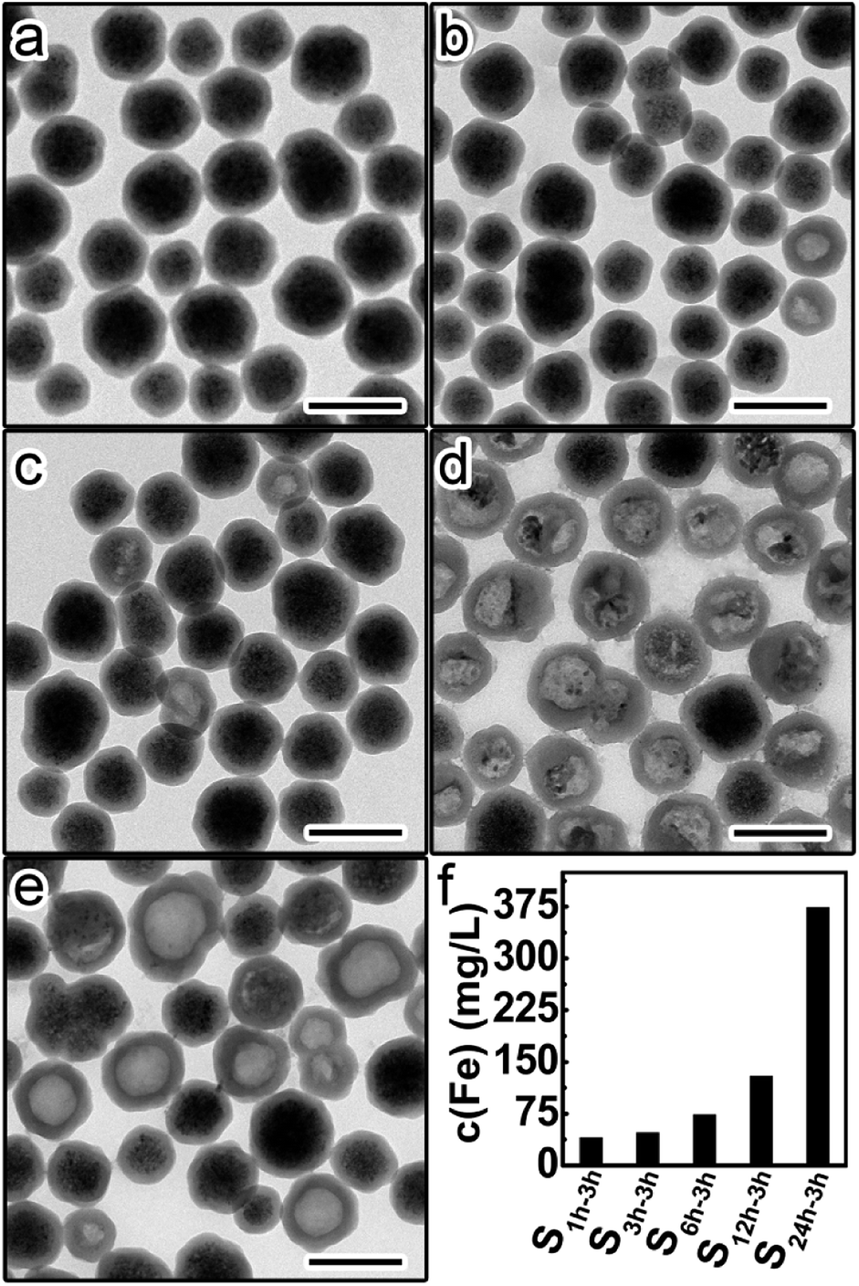 | ||
| Fig. 4 TEM images of the precipitates from different etched samples: (a) S1 h-3 h, (b) S3 h-3 h, (c) S6 h-3 h, (d) S12 h-3 h, and (e) S24 h-3 h. Scale bars are 200 nm. (f) Fe contents in the supernatants of different etched samples. | ||
Such discrepancy in the protective ability was even more significant if we extended the etching time to 10 hours. A similar trend in the amount of remaining Fe3O4 was found in the etched samples (Fig. S2a–e†). The difference in the Fe content of the supernatant is much more pronounced between S1 h-10 h and any of the other four etched samples (Fig. S2f†). These results further demonstrate that the protective ability of silica shells is strongly dependent on their aging degrees.
The higher etching rate of Fe3O4 for samples with more aged silica shells was also evidenced by the magnetization measurements. Fig. 5a shows the hysteresis loops of the above-mentioned five samples before etching. All samples were superparamagnetic at room temperature with negligible coercive forces (Hc) and remanent magnetizations (Mr). The saturation magnetizations were almost the same for this set of five samples. The slight difference resulted from the small variance in the shell thickness. After the 10 hour etching, we observed an obvious and continuous drop in the saturation magnetization (Ms) from S1 h-10 h to S24 h-10 h (Fig. 5b and c). This trend is consistent with the fact that more amounts of Fe3O4 were etched away for samples with more aged silica shells.
 | ||
| Fig. 5 (a) The magnetic hysteresis loops of S1 h, S3 h, S6 h, S12 h, and S24 h at room temperature. (b) The magnetic hysteresis loops of precipitates of S1 h-10 h, S3 h-10 h, S6 h-10 h, S12 h-10 h, and S24 h-10 h at room temperature. (c) Relative drop of the saturation magnetization after etching. | ||
As shown above, we found that silica shells with higher aging degrees are more permeable to ions. One plausible explanation for this observed trend is that the wettability of silica shells is affected by their aging degrees. Compared with the Si–OC2H5 group, the Si–OH group exhibits stronger hydrogen bonding ability with water and is, thus, more hydrophilic. The presence of more hydrophobic Si–OC2H5 groups in less aged silica shells, as confirmed by FT-IR studies, hinders the transportation of water molecules and hydrated ions (such as H+, Fe2+ and Fe3+). In contrast, the ionic permeability is greatly improved for more aged silica shells with a lower number of Si–OC2H5 groups but a higher concentration of hydrophilic Si–OH groups. One may propose another possibility that the aging process may create pores that serve as the ionic channels.32 However, no micropores or mesopores were found in either S1 h or S24 h from the Brunauer–Emmett–Teller (BET) measurements (Fig. S3†). It is most likely that the contrast in the wettability accounts for the observed trend. While further studies are necessary to fully elucidate the mechanism, the present study clearly demonstrates that the protective ability of silica shells can be chemically tuned by simply varying the aging degree.
Besides Fe3O4 CNCs, we further studied the etching of silica-coated α-Fe2O3 nanoparticles in an attempt to justify the versatility of the aging degree effect. Ellipsoidal α-Fe2O3 nanoparticles were coated with a thin layer of silica to prepare two α-Fe2O3@SiO2 samples with the same shell thickness (Fig. S4a and b†). The sol–gel reaction time was varied between 1 hour and 24 hours. After being treated in HCl under the same conditions, more α-Fe2O3 were etched away for the 24 hour sample (Fig. S4c–f†). These results again suggest that silica shells with higher aging degree exhibit higher ionic permeability regardless of the core composition and particle shape.
Thanks to the improved understanding of the aging degree effect, it is now possible to rationally tune the protective ability of silica shells without changing the thickness, e.g. simply by adjusting the sol–gel reaction time. Finally, we demonstrate the use of thin but low-permeability shells to improve the cycling stability of iron oxide nanoparticles when used in the removal of metal ions. Notably, the desorption of metal ions is usually carried out under strongly acidic conditions (e.g. 1 M HCl). This raises the concern on the etching of iron oxide and the decrease of the recycling efficiency of nanoparticles through magnetic separation. Two samples S1 h and S24 were functionalized with amino groups. The modified samples (denoted as S1 h–NH2 and S24 h–NH2, respectively) were then used as the adsorbents in the removal of Cu2+. Magnetic separation was used for the recovering and cleaning of the particles. In the first cycle, both magnetic nanoparticles could be quickly separated from the dispersion within 60 seconds (Fig. 6a and b inset). TEM images revealed that the core–shell structures remained intact after the first cycle (Fig. 6a and b). However, the difference between the two samples appeared gradually during the cycling tests. For example, in the 8th cycle, no obvious drop in the separation efficiency was found for S1 h–NH2 (Fig. 6c inset). This is consistent with the preservation of the Fe3O4 cores after 8 cycles (Fig. 6c). In contrast, severe etching of Fe3O4 occurred for S24 h–NH2 (Fig. 6d). Consequently, the magnetic separation process became much slower, leading to unwanted losses of adsorbents (Fig. 6d inset). It is believed that these thin but low-permeability silica shells can also stabilize nanoparticles with different compositions and functionalities, facilitating their applications in different areas.
 | ||
| Fig. 6 TEM image of (a) S1 h–NH2, (b) S24 h–NH2, (c) S1 h–NH2 after 8 cycles of Cu2+ removal experiments, and (d) S2 4h–NH2 after 8 cycles of Cu2+ removal experiments. Scale bars are 200 nm. The inset in each image shows the corresponding samples dispersed in water after magnetic separation for 60 s. | ||
4. Conclusions
In summary, we have systematically studied the effect of the aging degree on the ionic permeability of silica shells. Contradictory to common impressions, we found that the ionic permeability of silica shells increased rather than decreased with the increasing aging degree. This trend may be explained by the chemical nature of the silica shell that affects the wettability, and thereby the transportation of water molecules and hydrated ions. More importantly, our study provides a feasible and effective way for chemically improving the protective ability of silica shells by simply controlling the sol–gel reaction time, which does not rely on the increase of the shell thickness that usually scarifies the performance of nanoparticles. Such insights into the protective ability of sol–gel derived silica would facilitate the practical implementation of silica-coated nanoparticles in the field of environmental remediation, demonstrated by a model experiment for repetitive Cu ion removal from water, as well as other potential applications in photonics, catalysis, and biomedicine.Conflicts of interest
There are no conflicts to declare.Acknowledgements
We acknowledge the support from the Natural Science Foundation of Jiangsu Province (BK20160309, 1601042C), the National Natural Science Foundation of China (Grant No. 51802208, 51373188, 21401135, 51772200), the China Postdoctoral Science Foundation (2017M611893), 111 project, the Collaborative Innovation Centre of Suzhou Nano Science & Technology, and the Priority Academic Program Development of Jiangsu Higher Education Institutions (PAPD) and Qing Lan Project.Notes and references
- X. Xia, Y. Wang, A. Ruditskiy and Y. Xia, Adv. Mater., 2013, 25, 6313–6333 CrossRef CAS PubMed
.
- M. Auffan, J. Rose, M. R. Wiesner and J.-Y. Bottero, Environ. Pollut., 2009, 157, 1127–1133 CrossRef CAS PubMed
- G. D. Moon, S. Ko, Y. Min, J. Zeng, Y. Xia and U. Jeong, Nano Today, 2011, 6, 186–203 CrossRef CAS
- C. Levard, E. M. Hotze, G. V. Lowry and G. E. Brown, Environ. Sci. Technol., 2012, 46, 6900–6914 CrossRef CAS PubMed
- J. B. Rivest and P. K. Jain, Chem. Soc. Rev., 2013, 42, 89–96 RSC
- L. Xu, H.-W. Liang, H.-H. Li, K. Wang, Y. Yang, L.-T. Song, X. Wang and S.-H. Yu, Nano Res., 2014, 8, 1081–1097 CrossRef
- L. Xu, H.-W. Liang, Y. Yang and S.-H. Yu, Chem. Rev., 2018, 118, 3209–3250 CrossRef CAS PubMed
- Q. Zhang, W. Wang, J. Goebl and Y. Yin, Nano Today, 2009, 4, 494–507 CrossRef CAS
- G. Jianping and Y. Yadong, Adv. Mater., 2008, 20, 3485–3491 CrossRef
- J. Ge, L. He, J. Goebl and Y. Yin, J. Am. Chem. Soc., 2009, 131, 3484–3486 CrossRef CAS PubMed
- L. Tang, B. Han, K. Persson, C. Friesen, T. He, K. Sieradzki and G. Ceder, J. Am. Chem. Soc., 2010, 132, 596–600 CrossRef CAS PubMed
- L. Tang, X. Li, R. C. Cammarata, C. Friesen and K. Sieradzki, J. Am. Chem. Soc., 2010, 132, 11722–11726 CrossRef CAS PubMed
- Y. Zhang, M. Wang, Y.-g. Zheng, H. Tan, B. Y.-w. Hsu, Z.-c. Yang, S. Y. Wong, A. Y.-c. Chang, M. Choolani, X. Li and J. Wang, Chem. Mater., 2013, 25, 2976–2985 CrossRef CAS
- Y. Bai, C. Gao and Y. Yin, Nanoscale, 2017, 9, 14875–14880 RSC
- S. H. Joo, J. Y. Park, C.-K. Tsung, Y. Yamada, P. Yang and G. A. Somorjai, Nat. Mater., 2008, 8, 126 CrossRef PubMed
- R. Hao, R. Xing, Z. Xu, Y. Hou, S. Gao and S. Sun, Adv. Mater., 2010, 22, 2729–2742 CrossRef CAS PubMed
- Y. Hu, L. He and Y. Yin, Small, 2012, 8, 3795–3799 CrossRef CAS PubMed
- F. Ge, M.-M. Li, H. Ye and B.-X. Zhao, J. Hazard. Mater., 2012, 211–212, 366–372 CrossRef CAS PubMed
- S. A. Elfeky, S. E. Mahmoud and A. F. Youssef, J. Adv. Res., 2017, 8, 435–443 CrossRef CAS PubMed
- K. Zargoosh, H. Abedini, A. Abdolmaleki and M. R. Molavian, Ind. Eng. Chem. Res., 2013, 52, 14944–14954 CrossRef CAS
- S. Bao, K. Li, P. Ning, J. Peng, X. Jin and L. Tang, Appl. Surf. Sci., 2017, 393, 457–466 CrossRef CAS
- J. Wang, S. Zheng, Y. Shao, J. Liu, Z. Xu and D. Zhu, J. Colloid Interface Sci., 2010, 349, 293–299 CrossRef CAS PubMed
- X. Xin, Q. Wei, J. Yang, L. Yan, R. Feng, G. Chen, B. Du and H. Li, Chem. Eng. J., 2012, 184, 132–140 CrossRef CAS
- J. Zhang, S. Zhai, S. Li, Z. Xiao, Y. Song, Q. An and G. Tian, Chem. Eng. J., 2013, 215–216, 461–471 CrossRef CAS
- C. Shan, Z. Ma, M. Tong and J. Ni, Water Res., 2015, 69, 252–260 CrossRef CAS PubMed
- I. Lee, M. A. Albiter, Q. Zhang, J. Ge, Y. Yin and F. Zaera, Phys. Chem. Chem. Phys., 2011, 13, 2449–2456 RSC
- I. Lee, Q. Zhang, J. Ge, Y. Yin and F. Zaera, Nano Res., 2011, 4, 115–123 CrossRef CAS
- S. A. Jadhav, R. Nisticò, G. Magnacca and D. Scalarone, RSC Adv., 2018, 8, 1246–1254 RSC
- S. L. C. Pinho, G. A. Pereira, P. Voisin, J. Kassem, V. Bouchaud, L. Etienne, J. A. Peters, L. Carlos, S. Mornet, C. F. G. C. Geraldes, J. Rocha and M.-H. Delville, ACS Nano, 2010, 4, 5339–5349 CrossRef CAS PubMed
- H. M. Joshi, M. De, F. Richter, J. He, P. V. Prasad and V. P. Dravid, J. Nanopart. Res., 2013, 15, 1448 CrossRef
- J. Kang, Y. Li, Y. Chen, A. Wang, B. Yue, Y. Qu, Y. Zhao and H. Chu, Mater. Res. Bull., 2015, 71, 116–121 CrossRef CAS
- T. Zhao, N. Goswami, J. Li, Q. Yao, Y. Zhang, J. Wang, D. Zhao and J. Xie, Small, 2016, 12, 6537–6541 CrossRef CAS PubMed
- C. Ma, C. Li, N. He, F. Wang, N. Ma, L. Zhang, Z. Lu, Z. Ali, Z. Xi, X. Li, G. Liang, H. Liu, Y. Deng, L. Xu and Z. Wang, J. Biomed. Nanotechnol., 2012, 8, 1000–1005 CrossRef CAS PubMed
- B. Wang, X. He, Z. Zhang, Y. Zhao and W. Feng, Acc. Chem. Res., 2013, 46, 761–769 CrossRef CAS PubMed
- C. Yu, C. Hangrong and S. Jianlin, Adv. Mater., 2013, 25, 3144–3176 CrossRef PubMed
- J. Gao, X. Ran, C. Shi, H. Cheng, T. Cheng and Y. Su, Nanoscale, 2013, 5, 7026–7033 RSC
- T. Sugimoto, Y. Wang, H. Itoh and A. Muramatsu, Colloids Surf., A, 1998, 134, 265–279 CrossRef CAS
- P. Yang, H. Li, S. Zhang, L. Chen, H. Zhou, R. Tang, T. Zhou, F. Bao, Q. Zhang, L. He and X. Zhang, Nanoscale, 2016, 8, 19036–19042 RSC
- M. Cheng, Z. Wang, Q. Lv, C. Li, S. Sun and S. Hu, J. Hazard. Mater., 2018, 341, 198–206 CrossRef PubMed
- S. Zhang, C. Li, Y. Yu, Z. Zhu, W. Zhang, R. Tang, W. Sun, W. Xie, Y. Li, J. Yu, L. He and X. Zhang, J. Mater. Chem. C, 2018, 6, 5528–5535 RSC
- Z. Zhu, S. Zhang, C. Li, J. Zhang, J. Yu, X. Du, L. He and X. Zhang, Phys. Chem. Chem. Phys., 2018, 20, 1440–1446 RSC
- W. Stöber, A. Fink and E. Bohn, J. Colloid Interface Sci., 1968, 26, 62–69 CrossRef
- Y. Hu, Q. Zhang, J. Goebl, T. Zhang and Y. Yin, Phys. Chem. Chem. Phys., 2010, 12, 11836–11842 RSC
- Y. J. Wong, L. Zhu, W. S. Teo, Y. W. Tan, Y. Yang, C. Wang and H. Chen, J. Am. Chem. Soc., 2011, 133, 11422–11425 CrossRef CAS PubMed
- G. B. Alexander, W. M. Heston and R. K. Iler, J. Phys. Chem., 1954, 58, 453–455 CrossRef CAS
- G. H. Du, Z. L. Liu, X. Xia, Q. Chu and S. M. Zhang, J. Sol-Gel Sci. Technol., 2006, 39, 285–291 CrossRef CAS
- R. Al-Oweini and H. El-Rassy, J. Mol. Struct., 2009, 919, 140–145 CrossRef CAS
Footnote |
| † Electronic supplementary information (ESI) available. See DOI: 10.1039/c8ra08936a |
| This journal is © The Royal Society of Chemistry 2018 |