
 Open Access Article
 This Open Access Article is licensed under a
 Creative Commons Attribution 3.0 Unported Licence
A one-step synthesis of rare-earth phosphate–borosilicate glass composites†
Giovanni Donato,
Derek Holzscherer,
Jeremiah C. Beam and
Andrew P. Grosvenor*
and
Andrew P. Grosvenor*
Department of Chemistry, University of Saskatchewan, Saskatoon, S7N 5C9, SK, Canada. E-mail: andrew.grosvenor@usask.ca
First published on 20th November 2018
Abstract
A new 1-step method for synthesizing glass–ceramic composites consisting of rare earth phosphates (REPO4) dispersed in borosilicate glass (BG) is reported herein as an alternative to the 2-step approach that is traditionally used. The effect of annealing time and annealing temperature on the formation of the 1-step glass–ceramic composites was investigated. Backscattered electron images and energy dispersive X-ray maps were collected to observe the morphology and chemical distribution in the glass–ceramic composites. X-ray diffraction was used to study the long-range order and X-ray absorption near edge spectroscopy was used to study the local environment of La, Y, P and Si. All analyses showed glass–ceramic composites made by the 1 and 2-step methods were similar to each other except for the Si L2,3-edge XANES spectra, which showed a slight change between the glass–ceramic composite materials made by the different synthesis methods. Xenotime-type phosphates (YPO4) were observed to be more soluble in the borosilicate glass than the monazite-type phosphates (LaPO4). This was attributed to the difference in the field strength of the rare-earth ions as a result of the difference in the ionic radii. Glass–ceramic composites made by the 1-step method were shown to form in 1 day at 1100 °C and in 3 days at 1000 °C without a significant change in glass or ceramic composition compared to the 1-step composite synthesized at 1100 °C for 3 days.
1 Introduction
Glass–ceramic composites are heterogeneous materials consisting of ceramic crystallites dispersed in a glass matrix. These materials are of interest because they can have improved chemical and mechanical properties compared to glass alone.1,2 The improved properties can be caused by the presence of crystallites in the glass and the properties can therefore be tailored to an application by changing the composition/amount of either the glass or ceramic phase.3 These materials have found uses for many applications, including: as photoluminescence materials; in fuel cells; as bioactive agents; as textiles; as integrated circuits; and as waste forms to sequester high level nuclear waste.3–6High level nuclear waste is a product of the nuclear fuel cycle and consists, in part, of radioactive actinides.7–9 One method proposed to sequester high level waste is to incorporate these elements into a waste form followed by placement in a geological repository.9–11 This removes the radioisotopes from the environment and allows them to decay in a contained location. Three potential waste forms that have attracted attention are: glasses; ceramics; and glass–ceramic composites.12–15 Glass–ceramic composites capitalize on the advantages of both the glass and ceramic.12,16 The ceramic crystallites can incorporate actinides into the crystal structure giving the material a high waste loading potential as well as a high chemical resistance and the glass acts as a secondary barrier for the actinides while also being able to accommodate smaller fission products.9,12,16
Glass–ceramic composites containing rare-earth phosphates in a glass matrix have been proposed as a potential waste form to sequester high level nuclear waste.2,17 Borosilicate glass (BG) is one proposed type of glass to be used for this application because of the chemical durability of this material and the prospect of recycling glass from other industries.18 Natural rare-earth phosphates (REPO4) have been found to incorporate U and Th while remaining crystalline over geological timescales.11,19 Anhydrous rare-earth phosphates can adopt the monazite or xenotime structures.20–22 The monazite structure (Fig. 1a) is formed by the light rare-earth elements (La–Gd) and is monoclinic with the space group P21/n.13,19,23 The rare earth ion in monazite is 9-coordinate while P is 4-coordinate. The xenotime structure (Fig. 1b) is formed by the heavy rare-earth elements (Dy–Lu, and Y) and is tetragonal with the space group I41/amd.13,19,24 The rare earth ion in xenotime is 8-coordinate while P is also 4-coordinate in this structure.
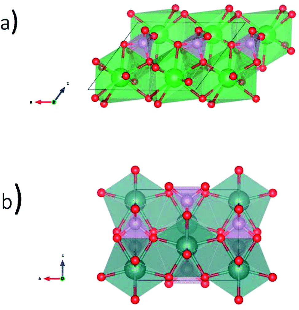 | ||
| Fig. 1 Crystal structures of REPO4 as (a) monazite (RE = La to Gd) and (b) xenotime (RE = Tb to Lu & Y). | ||
Glass–ceramic composite materials are normally synthesized using a multistep process. One type of synthesis involves a 2-step method where the ceramic and glass phases are synthesized separately before being mixed and then annealed to form a composite material.12,16,25–29 The high level waste stream would be added during the production of the ceramic phase which would ensure all the minor actinides would be partitioned into the ceramic phase.27 A 1-step method is investigated here where all precursors are mixed together from the beginning followed by annealing. A 1-step method would have various advantages over a 2-step method. For example, a 1-step method would save on fabrication costs and be compatible with already existing glass producing infrastructure due to being able to form the glass–ceramic composite by the same melt-quench technique used to make glass.30 Additionally, the production of glass–ceramic composite waste forms by this method would be safer since the high-level waste would not need to be handled for as long a period. The partitioning of a complex waste stream into the ceramic and glass phases is outside the scope of this study; however, it is envisioned that the high-level waste stream would be incorporated during the single step reaction similar to the process used to make a glass waste form.31 Glass–ceramic composites containing LaPO4 or YPO4 crystallites dispersed in a borosilicate glass matrix were studied using powder X-ray diffraction (XRD), electron microprobe, and X-ray absorption near edge spectroscopy (XANES) to study the long-range order, morphology, and local chemical environment, respectively.
2 Experimental
2.1 Synthesis
The general synthesis strategies for synthesizing LaPO4–BG composites made by the 1- and 2-step methods are shown in Scheme 1.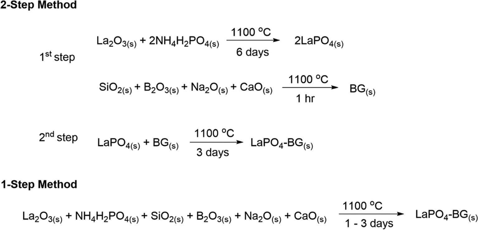 | ||
| Scheme 1 General synthesis strategies for making LaPO4–BG composites using 1- and 2-step synthesis methods. | ||
2.1.1.1 REPO4. LaPO4 (monazite) was prepared using the ceramic method. La2O3 (Alfa Aesar; 99.9%) and NH4H2PO4 (Alfa Aesar; 99.9%) were ground and mixed stoichiometrically before being pressed into a pellet and annealed at 1100 °C for 6 days in an alumina crucible with grinding and pelleting occurring in 3 day intervals followed by quench cooling in air. In order to obtain pure phase xenotime, YPO4 (xenotime) was synthesized using a wet chemical method that was described previously by Kijkowska et al.32 Powdered Y2O3 (Alfa Aesar 99.9%) was added to 13.7 mL of 85 vol% H3PO4 and stirred to make a solution with a mole ratio of 1
![[thin space (1/6-em)]](https://www.rsc.org/images/entities/char_2009.gif) :100 (Y2O3:PO43−). The solution was then diluted by adding 100 mL of distilled water. After the water was added, the solution was refluxed at 130 °C for 2 hours and the precipitate was filtered and washed using distilled water. The precipitate was dried in a fumehood overnight before being pressed into a pellet and annealed at 1100 °C for 3 days in an alumina crucible followed by quench cooling in air.
:100 (Y2O3:PO43−). The solution was then diluted by adding 100 mL of distilled water. After the water was added, the solution was refluxed at 130 °C for 2 hours and the precipitate was filtered and washed using distilled water. The precipitate was dried in a fumehood overnight before being pressed into a pellet and annealed at 1100 °C for 3 days in an alumina crucible followed by quench cooling in air.
2.1.1.2 Borosilicate glass. Borosilicate glass was also made by the ceramic method. The mole percentage was as follows: 63.5% SiO2 (EMD Millipore), 16.9% B2O3 (Alfa Aesar; 99.98%), 16.5% Na2O (Alfa Aesar), and 3.1% CaO (Acros Organics; 97+%). The oxide powders were ground and mixed using a mortar and pestle, pressed into a pellet at 6 MPa, and annealed in 5% Au/95% Pt crucibles at 1100 °C for 1 hour followed by quench cooling in water.
2.1.1.3 REPO4–BG composite. The 2-step glass–ceramic composites were formed by grinding and mixing the pure ceramic and glass with a 20, 40 or 50 wt% ceramic loading to make LaPO4–BG or YPO4–BG composite materials. The 20 and 40 wt% glass–ceramic composites were annealed in 5% Au/95% Pt crucibles at 1100 °C for 3 days followed by quench cooling in water. The 50 wt% ceramic LaPO4–BG composite made by the 2-step method was annealed for 1 hour at 1100 °C after grinding and mixing the pure ceramic and glass followed by quench cooing in water. The total synthesis time of REPO4–BG composites by the 2-step method was 6–9 days (6 and 3 days for the synthesis of LaPO4 and YPO4, respectively, plus 3 days to form the composite). The glass–ceramic composite materials made by the 2-step method are described in Table 1.
| Sample name | Composition (RE = La, Y) | Synthesis method | Annealing time | Annealing temperature |
|---|---|---|---|---|
| 20% 2-step | 20 wt% ceramic REPO4–BG | 2-Step | 3 days | 1100 °C |
| 40% 2-step | 40 wt% ceramic REPO4–BG | 2-Step | 3 days | 1100 °C |
| 50% 2-step | 50 wt% ceramic REPO4–BG | 2-Step | 1 hour | 1100 °C |
| 20% 1-step | 20 wt% ceramic REPO4–BG | 1-Step | 3 days | 1100 °C |
| 40% 1-step | 40 wt% ceramic REPO4–BG | 1-Step | 3 days | 1100 °C |
| 50% 1-step | 50 wt% ceramic REPO4–BG | 1-Step | 3 days | 1100 °C |
| 1100 C | 40 wt% ceramic REPO4–BG | 1-Step | 3 days | 1100 °C |
| 1000 C | 40 wt% ceramic REPO4–BG | 1-Step | 3 days | 1000 °C |
| 900 C | 40 wt% ceramic REPO4–BG | 1-Step | 3 days | 900 °C |
| 3 days | 40 wt% ceramic REPO4–BG | 1-Step | 3 days | 1100 °C |
| 2 days | 40 wt% ceramic REPO4–BG | 1-Step | 2 days | 1100 °C |
| 1 day | 40 wt% ceramic REPO4–BG | 1-Step | 1 day | 1100 °C |
2.2 Powder X-ray diffraction
Powder X-ray diffraction patterns were collected using a PANalytical Empyrean instrument equipped with a Co or Cu Kα1,2 source or a Rigaku instrument equipped with a Cu Kα1,2 source. The patterns collected using the Co X-ray source were converted to the equivalent 2θ if a Cu source was used using the Bragg equation for consistency. Patterns were analyzed using the Powder Cell for Windows (PCW) software program.332.3 Electron microprobe
Electron microprobe images were collected from the 50 wt% ceramic LaPO4–BG composites synthesized by the 1 and 2-step methods as well as the 40 wt% ceramic YPO4–BG composites synthesized by the 1 and 2-step methods. Backscattered electron (BSE) images and electron dispersive X-ray spectroscopy (EDX) maps as well as EDX spectra were collected using a JEOL 8600 electron microprobe instrument. The samples were prepared by polishing the surface using diamond paste and were coated in carbon to reduce charging effects. The images and maps were collected using a magnification of 1000×.2.4 XANES
038 eV.34 The La L1-edge XANES spectra were collected using a step size of 0.15 eV through the absorption edge. The ratio of He:N2 in the ionization chambers during collection of the La L1-edge XANES spectra was 70% He:30% N2 in the I0 chamber and 100% N2 in the It and Iref chambers. The La L1-edge XANES spectra were calibrated by collecting a Cr K-edge XANES spectrum from Cr metal foil and setting the first derivative of the absorption edge to 5989 eV.35 The Y K-edge XANES spectra were collected using a step size of 0.3 eV through the absorption edge. The ratio of Ar:N2 in the ionization chambers during the collection of the Y K-edge spectra was 100% N2 in I0 and 50% Ar:50% N2 in It and Iref. The Y K-edge XANES spectra were calibrated by collecting a Zr K-edge XANES spectrum from Zr metal foil and setting the first derivative of the absorption edge to 17998 eV.35 All XANES spectra were normalized, calibrated, and analysed using the Athena software program.363 Results and discussion
3.1 Powder XRD
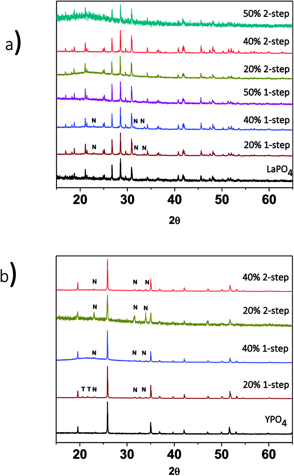 | ||
| Fig. 2 XRD patterns from (a) 1 and 2-step LaPO4–BG composites with 20, 40 and 50 wt% ceramic and (b) 1- and 2-step YPO4–BG composites with 20 and 40 wt% ceramic. T = tridymite peaks, N = nagelschmidtite phase peaks. | ||
The effect of changing the annealing temperature and annealing time on the crystal structure of the ceramic phase(s) was also investigated. The composites made by the 1-step method were synthesized at 1100 °C for 1, 2 and 3 days to observe how the structure changed depending on the annealing time. Fig. 3a shows the XRD patterns from the 40% LaPO4–BG composites annealed for 1, 2, and 3 days. Annealing for 1, 2, and 3 days at 1100 °C forms a composite which contains LaPO4 as the major phase and nagelschmidtite as the minor phase. An annealing time of one day is a much shorter time period to form monazite when compared to the 6 days it typically takes to form the pure ceramic at this temperature using the ceramic method.13 The decrease in time can be attributed to the glass being in a liquid phase at this temperature.3 This increases the mobility of the RE3+ and PO43− ions and allows them to diffuse through the sample and form monazite in a much shorter time.
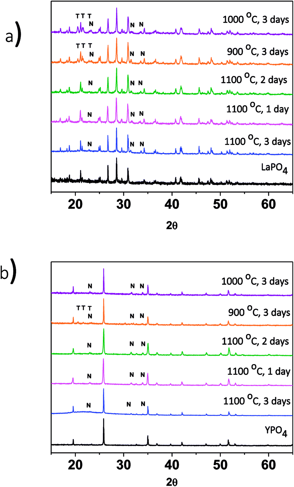 | ||
| Fig. 3 XRD patterns from (a) 1-step LaPO4–BG composites annealed at 900–1100 °C and 1–3 days and (b) 1-step YPO4–BG composites annealed at 900–1100 °C and 1–3 days. T = tridymite peaks, N = nagelschmidtite peaks. | ||
The effect of annealing temperature on the formation of the glass–ceramic composites was also investigated by synthesizing glass–ceramic composites using annealing temperatures of 1100, 1000, and 900 °C for 3 days. Below 1100 °C, LaPO4, tridymite (crystalline SiO2), and nagelschmidtite were observed to form (Fig. 3a). The presence of crystalline SiO2 is unwanted in a waste form and should be avoided because crystalline SiO2 can undergo phase transformations at low temperatures, which leads to volume changes and the possibility of the waste form cracking.29,39 No changes in the 2θ positions of the diffraction peaks or changes in the intensity ratios of the diffraction peaks were observed, which suggests that little to no glass precursors were incorporated in the ceramic phase.
3.2 Electron microprobe
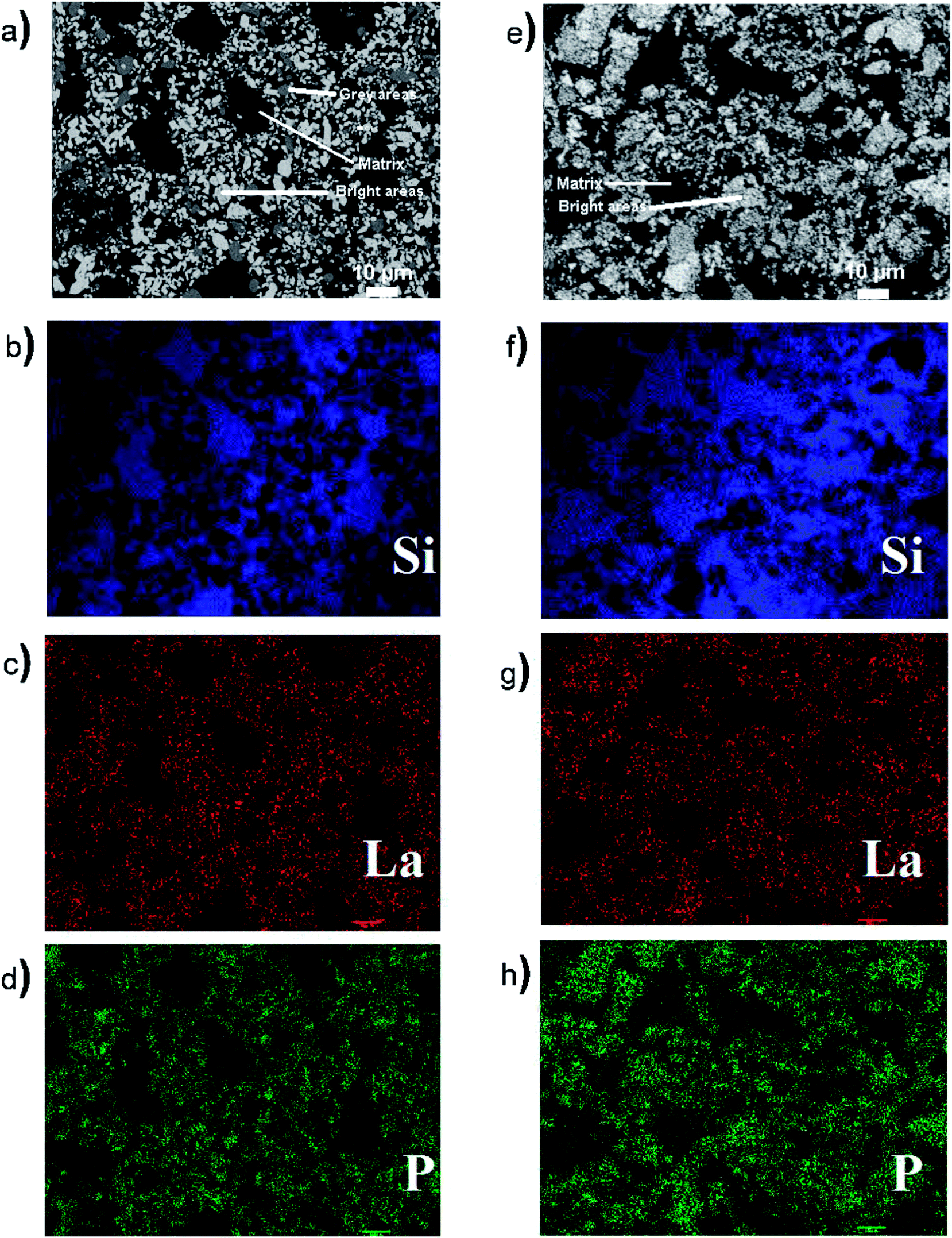 | ||
| Fig. 4 (a) Backscattered electron image of 50 wt% ceramic LaPO4–BG composite synthesized by the 1-step method, (b) Si EDX map of the composites made by the 1-step method, (c) La EDX map of the composites made by the 1-step method (d) P EDX map of the composites made by the 1-step method, (e) backscattered electron image of the 50 wt% ceramic LaPO4–BG composites synthesized by the 2-step method, (f) Si EDX map of composite made by the 2-step method, (g) La EDX map of the composite made by the 2-step method (h) P EDX map of the composite made by the 2-step method. | ||
Energy dispersive X-ray fluorescence (EDX) maps (Fig. 4) were also collected from 50 wt% LaPO4–BG composites annealed for 1 hour at 1100 °C to observe the elemental distribution in the different regions of the composite materials. The EDX maps from the composite material made by the 1-step method showed distinct regions containing high concentrations of P and La that correspond with the bright spots observed in the BSE image (Fig. 4d and c, respectively) while the matrix present in the BSE images showed a high concentration of Si in the corresponding EDX map (Fig. 4b), which corresponds to borosilicate glass. The EDX maps show discrete regions containing Si or La/P, respectively, indicating that there was very little, if any, La and P dissolved in the glass matrix. The EDX maps from the composite material made by the 2-step method also showed discrete regions containing La/P or Si (Fig. 4). The La and P EDX maps correlated with each other and correspond to the bright spots in the BSE image (cf., Fig. 4e, g, and h). The Si EDX map correspond to the matrix in the BSE image (cf., Fig. 4e and f). These results are similar to the results from the composite made by the 1-step method and further shows the similarity in the 1- and 2-step glass–ceramic composites despite the different synthesis methods.
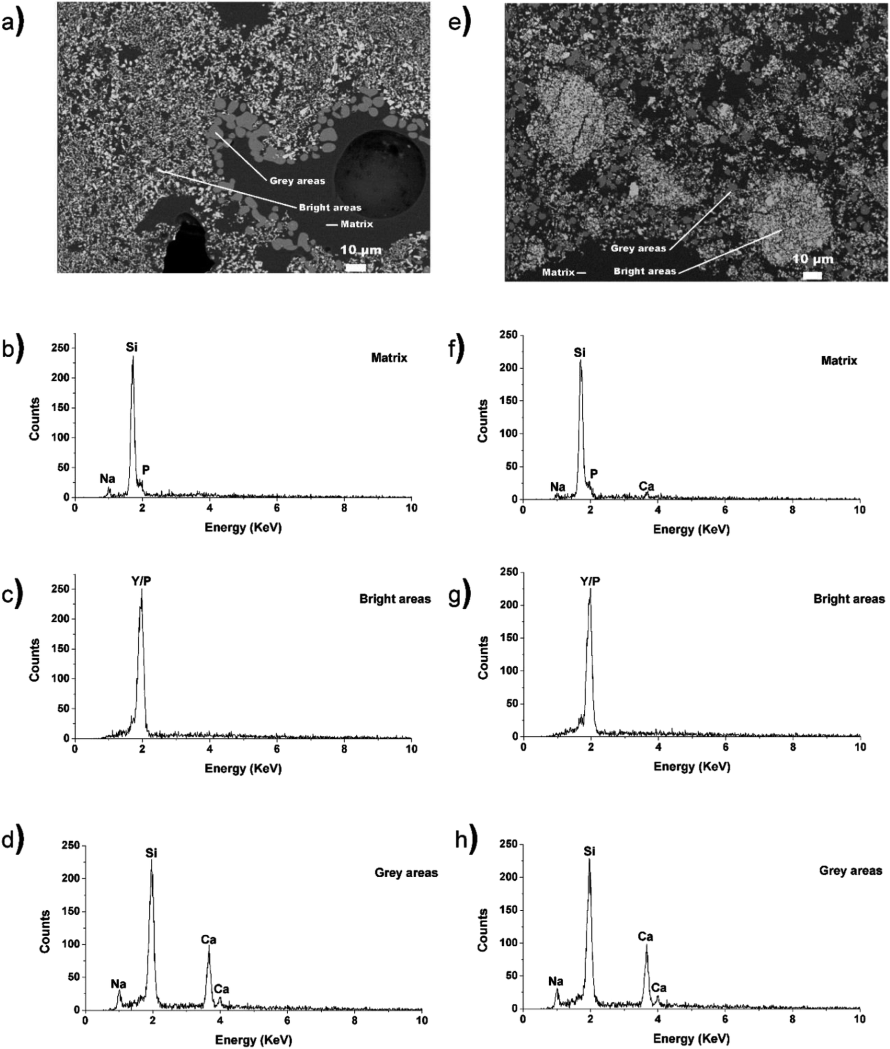 | ||
| Fig. 5 (a) Backscattered electron image of the 40 wt% ceramic YPO4–BG composites synthesized by the 1-step method, (b) EDX spectra taken of the matrix in the composite made by the 1-step method, (c) EDX spectra taken of the bright particles (YPO4) in the composite made by the 1-step method, (d) EDX spectra taken of the grey particles (minor crystal phase) in the composite made by the 1-step method, (e) backscattered electron image of the 40 wt% ceramic YPO4–BG composites synthesized by the 2-step method, (f) EDX spectra taken of the matrix in the composite made by the 2-step method, (g) EDX spectra taken of the bright particles (YPO4) in the composite made by the 2-step method, (h) EDX spectra taken of the grey particles (minor crystal phase) in the composite made by the 2-step method. | ||
EDX spectra were collected from the different regions of the micrographs corresponding to the glass matrix, YPO4, and nagelschmidtite in the composite materials made by the 1- and 2-step synthesis methods. The spectra taken from the YPO4 crystallites in the composite materials made by the 1- and 2-step method (bright areas; Fig. 5c and g) indicate the presence of Y and P. Spectra taken from the grey areas present in the composites made by the 1- and 2-step method (Fig. 5d and h) indicate the presence of Si, Na, and Ca. The absence of P in the spectra is surprising given the general formula of nagelschmidtite, Ca7−xNax(PO4)2+x(SiO4)2−x.43 Rare-earth elements (e.g. Nd) have also been found to stabilize the nagelschmidtite structure with higher silicon concentrations giving the general formula Ca7−xNdx(PO4)2−x(SiO4)2+x (0 ≤ x ≤ 1).44 A low intensity P signal in the EDX spectra could be overlapped by the large Si signal due to the proximity of the peaks and the resolution of the EDX detector used. The EDX spectra from the borosilicate glass (matrix; Fig. 5b and f) indicate the presence of Si, Na, P (and Ca in the case of the composite material synthesized by the 2-step method). This indicates that only a small amount of Ca was not crystallize into nagelschmidtite in the YPO4–BG composite material made by the 1-step method. The fluorescence signal from Y could be overlapped by the signal from P and Si in the EDX spectrum from the matrix (Fig. 5b and f) due to the similarity in energy of the peaks and the resolution of the detector. SEM and EDX maps were also collected from the 40 wt% YPO4–BG composite materials made by the 1- and 2-step methods from different spots on the samples (Fig. S1 in the ESI†). These maps suggest the presence of P and Y in the nagelschmidtite crystallite as well as the dissolution of YPO4 in the glass matrix.
3.3 XANES
 | ||
| Fig. 6 (a) La L1-edge XANES spectra taken from 1 and 2-step LaPO4–BG composites with 20, 40 and 50 wt% ceramic as well as pure LaPO4, La L1-edge XANES spectra taken from 40 wt% ceramic 1-step LaPO4–BG composites annealed at (b) 1–3 days at 1100 °C and (c) 900–1100 °C for 3 days. | ||
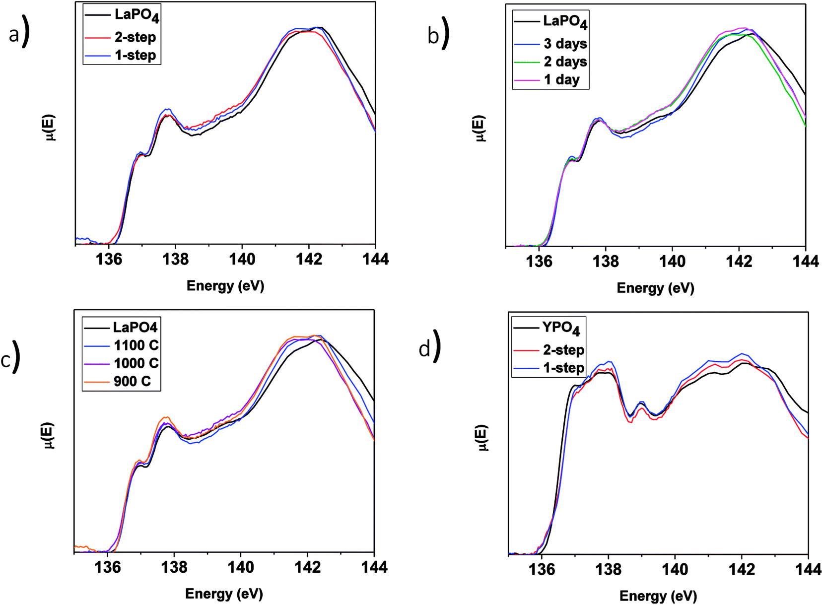
The La L1-edge XANES spectra from the glass–ceramic composite materials annealed for 1–3 days at 1100 °C and 1100–900 °C for 3 days are presented in Fig. 6b and c, respectively. All of the spectra were observed to be identical to the spectrum from the pure LaPO4 ceramic. Comparison of the La L1-edge XANES spectra (Fig. 6) and the XRD patterns (Fig. 2a and 3a) indicate that monazite can form within the composite materials using lower annealing temperatures than are generally used to form pure LaPO4 by the ceramic method and can form in as little as 1 day with little to no impact to the long-range order or local chemical environment of the LaPO4 monazite structure.
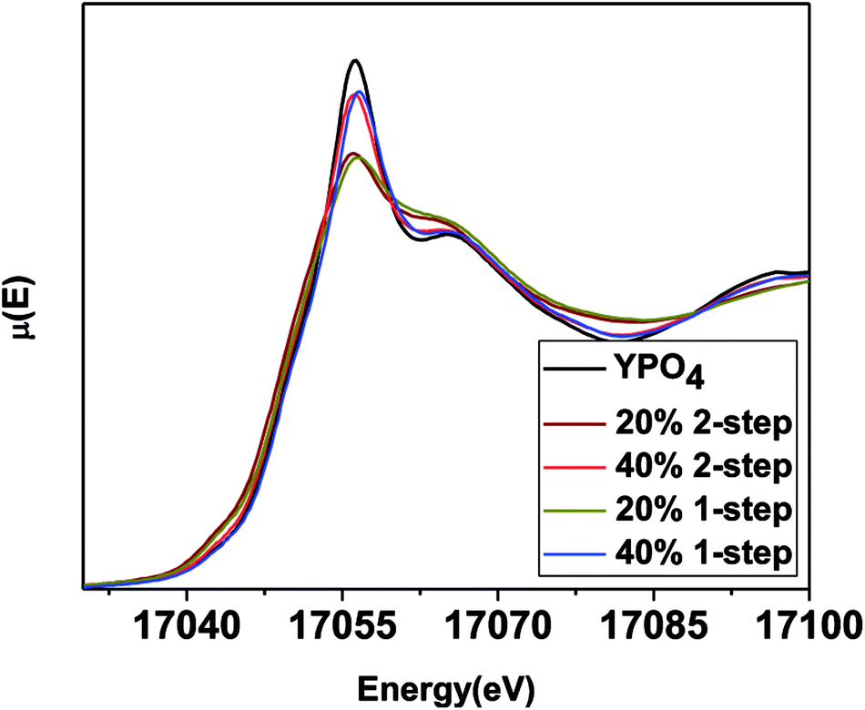 | ||
| Fig. 7 Y K-edge XANES spectra taken from 1 and 2-step YPO4–BG composites with 20 and 40 wt% ceramic as well as pure YPO4. | ||
The intensity of the main edge feature in the YPO4–BG composite materials (Fig. 7) increases while the pre-edge feature decreases in intensity as the ceramic loading increases. The Y K-edge XANES spectra were observed to overlap when comparing glass–ceramic composites formed by the 1 and 2-step methods having the same ceramic loading. This shows that while the intensities of the features in the XANES spectra (and as a result the local chemical environment of Y) are dependent on ceramic loading, they are independent of synthesis method. The Y K-edge XANES spectra from all glass–ceramic composite materials show changes when compared to the spectrum from YPO4, which indicates that Y adopted a lower average coordination number in these composite materials. This suggest that Y dissolved in the borosilicate glass under all conditions studied. The proportionate amount of Y dissolved in the glass is greater in the 20 wt% ceramic than in the 40 wt% ceramic, which indicates that YPO4 will only dissolve and be incorporated into the borosilicate glass up to a point, with the remaining Y being found in YPO4. More of the crystalline phase will therefore be observed when more YPO4 is loaded into the composite material.
The difference in solubility of the rare-earth phosphates in the glass matrix between the LaPO4–BG composites and the YPO4–BG composites can be explained by examining the structural roles and field strength of the rare earth elements. Field strength is based on the theory of coulombic fields and can help predict and explain how the different cations interact with each other in glass.52 This is done by looking at how the cations interact with and compete for O2− in order to satisfy their own local chemical requirements.52 The field strength is calculated by dividing the charge of the cation by the square of the cation–oxygen bond distance (FS = z/r2).53–56 Cations in a glass can be categorized as a network former, which makes up the glass network with bridging oxygen anions, a network modifier, which breaks up the network by introducing non-bridging oxygen anions, and network intermediates, which can act as either network formers or network modifiers depending on the glass composition.57 The category a cation falls into is largely based on the field strength and the bond strength between the cation and oxygen.10,56 Network modifiers have a general range in field strength from 0.1 to 0.4 and a typical bond strength of 10–50 kcal mol−1 whereas network intermediates have a field strength range of 0.5 to 1.0 and a typical bond strength of 50–70 kcal mol−1 while network formers have a field strength of >1.0 and bond strengths of >70 kcal mol−1.10,56 The rare-earth ions La3+ and Y3+ have field strengths of 0.50 and 0.57, respectively, and bond strengths of 58 kcal mol−1 (La–O) and 50 kcal mol−1 (Y–O).55,56,58 Y3+ has a higher field strength (0.57) than La3+ (0.50) due to the smaller ionic radius of Y3+.55 La3+ is on the edge of the field strength range between network modifiers and network intermediates and can act as a network modifier.55 Y3+ has been shown to break up the glass network or strengthen it in silicate glasses depending on composition and therefore it has been suggested that Y3+ can be classified as a network intermediate.51,59 This was also suggested to be true by Malchukova et al. for Gd3+, which has a similar field strength to Y3+ (0.55).18 In that study, Gd was doped into aluminoborosilicate glass (0–4.4 wt% of Gd2O3) and exposed to radiation in order to determine how these conditions effects the potential waste form.18 Of the amount of Gd3+ that was homogenously dissolved in the glass, the ratio of Gd3+ ions that acted as a network former and network modifier remained the same from 0.9–4.4 wt% of Gd2O3.18
By having a higher field strength, Y3+ is able to compete for O2− more successfully than La3+ and behave as a network intermediate, leading to a higher degree of incorporation into the glass structure and a higher solubility in borosilicate glass. It has also been shown that crystallization is more difficult to induce in rare-earth doped borosilicate glass when Y3+ is the rare earth compared to when La3+ is present, indicating a higher stability of Y in the glass matrix caused by the difference in structural roles.51
3.3.3.1 LaPO4–BG composites. The P L2,3-edge XANES spectra from the LaPO4–BG composites and pure LaPO4 are shown in Fig. 8 and were collected to observe any changes in the local chemical environment of P in the composite materials vs. the pure-phase ceramic. The P L2,3-edge XANES spectra from all LaPO4–BG composites and LaPO4 were observed to overlap, which suggests no change in the local chemical environment of P regardless of synthesis method, annealing temperature, or annealing time used to form the composite materials. Comparison of the La L1-edge and P L2,3-edge XANES spectra indicate that the local environment of La and P remain the same in the composite materials compared to pure LaPO4. This being said, this suggestion could be questioned when the P L2,3-edge XANES results from the YPO4–BG composites are considered (vide infra).
 | ||
| Fig. 8 P L2,3-edge XANES spectra of (a) 1 and 2-step 40 wt% ceramic LaPO4–BG composites, 1-step LaPO4–BG composites annealed at (b) 900–1100 °C for 3 days, (c) 1–3 days at 1100 °C as well as pure LaPO4 and (d) 1 and 2-step YPO4–BG composites with 20 and 40 wt% ceramic as well as pure YPO4. | ||
3.3.3.2 YPO4–BG composites. The P L2,3-edge XANES spectra from the YPO4–BG samples (Fig. 8d) indicate little to no change when compared to the spectrum from the pure-phase YPO4 ceramic. This is in contrast to the results from EDX spectra (Fig. 5) and Y K-edge XANES spectra (Fig. 7) from the YPO4–BG composite materials. Based on those results, some YPO4 was concluded to be dissolved in the glass matrix from the composite materials vs. the pure phase ceramic. The similarity between the P L2,3-edge XANES spectra despite whether P is located in the glass or ceramic phases in the composite materials suggests that the chemical environment of P is similar in the glass and ceramic phases. The examination of P L2,3-edge XANES spectra alone is therefore not appropriate for analysis of REPO4–BG composites and should be paired with other characterization techniques when analyzing REPO4–BG systems.
3.3.4.1 LaPO4–BG composites. The Si L2,3-edge XANES spectra from the LaPO4–BG composites are presented in Fig. 9. Fig. 9a compares the spectra from LaPO4–BG composites synthesized using the 1- and 2-step methods. The intensity ratio of the L2 and L3-edges change depending on the synthesis method used. These changes have been attributed to changes in the ordering of the glass.63 The Si L2,3-edge XANES spectra presented in Fig. 9b overlap each other showing no significant changes in the local chemical environment of Si regardless of annealing time. The spectra presented in Fig. 9a and b from the glass–ceramic composites are narrower and higher in energy than the spectra from borosilicate glass. The changes in the spectra between the glass–ceramic composite materials and borosilicate glass are a result of next nearest neighbour effects caused by the presence of metal cations. Fig. 9c shows spectra from LaPO4–BG composites annealed at 1100, 1000, and 900 °C. The Si L2,3-edge XANES spectra from the composite materials become sharper with decreasing annealing temperature. The sharpening of the spectra is indictive of partial crystallization in the glass.61 XRD patterns from these glass–ceramic composites showed the presence of crystalline SiO2 when they were annealed for 3 days at 1000 and 900 °C (Fig. 3a). Analysis of the Si L2,3-edge XANES spectra suggest that the amount of crystallization that occurred at 1000 °C was minor and did not affect the overall structure of the amorphous glass matrix in a significant way while analysis of the spectrum from the composite annealed at 900 °C suggested that the crystallization of SiO2 impacted the Si network to a much greater extent.
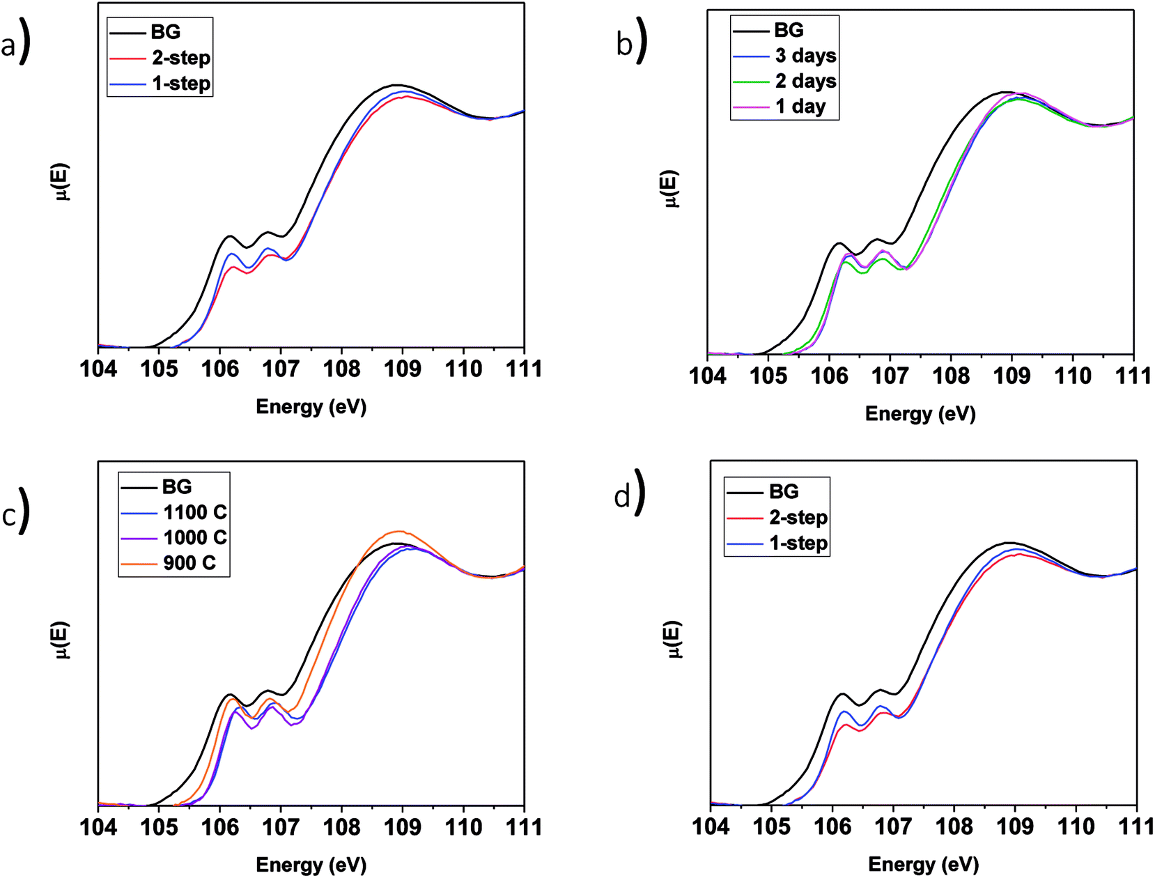 | ||
| Fig. 9 Si L2,3-edge XANES spectra of (a) 1 and 2-step 40 wt% ceramic LaPO4–BG composites, 1-step LaPO4–BG composites annealed at (b) 900–1100 °C for 3 days, (c) 1–3 days at 1100 °C and (d) 1 and 2-step YPO4–BG composites with 20 and 40 wt% ceramic as well as pure BG. | ||
3.3.4.2 YPO4–BG composites. The Si L2,3-edge XANES spectra of YPO4–BG composites made by the 1 and 2-step synthesis methods are narrower to higher energy than the spectrum from pure borosilicate glass. These changes, like in LaPO4–BG composites, are a result of next nearest neighbour effects caused by the metal cation in the Si–O–M bond except in these cases it is from Si–O–Y. When compared to each other, YPO4–BG glass–ceramic composite materials synthesized by the 1- and 2-step methods show the same changes observed in the LaPO4–BG composites (Section 3.3.4.1) in that the intensity ratio of the L2 and L3 edges changed depending on the synthesis method. The cause of the change in the glass ordering in these materials seems to be linked to the synthesis method itself and not by how much ceramic dissolves in the glass. This is because the amount of ceramic dissolved in the glass was the same regardless of synthesis method and also this change in relative intensities was observed in the Si L2,3-edge XANES spectra from LaPO4–BG composite materials, where no dissolution took place.
4 Conclusions
Composite materials of rare-earth phosphate crystallites dispersed in borosilicate glass made by the 1- and 2-step methods were synthesized. Powder XRD, electron microprobe, and XANES have been utilized to examine the long-range order, morphology, chemical distribution, and local environment of glass–ceramic composites formed using either a 1- or 2-step method. Glass–ceramic composite materials made by the 1- and 2-step method showed either LaPO4 or YPO4 as the major crystal phase depending on the rare earth oxide used. All other characterization techniques showed 1- and 2-step composites containing the same rare-earth ion were similar to each other except by Si L2,3-edge XANES. The change in the relative intensities of the Si L2 and L3-edge are indicative of a change in the ordering in the glass as a result of the new synthesis method (i.e., 1-step).Glass–ceramic composite materials were also able to be synthesized in 1 day at 1100 °C and in 3 days at 1000 °C without any significant change in the glass or ceramic phases relative to the composite material synthesized for 3 days at 1100 °C. Different solubilities of LaPO4 and YPO4 in borosilicate glass were observed due to the different field strength of the rare earth ion present in the composite material. This difference in field strength lead to a difference in structural roles of La3+ (network modifier) and Y3+ (network intermediate). Ceramic crystallites dissolving in the glass matrix within a glass–ceramic composite waste form would minimize the inherent strengths of this class of waste form such as increased chemical stability and a double barrier (ceramic + glass). Consideration of the field strength of the ions used must be accounted for when synthesizing this system for nuclear waste sequestration applications. The 1-step synthesis method has shown potential as a synthetic strategy to prepare glass–ceramic nuclear waste forms.
Conflicts of interest
There are no conflicts to declare.Acknowledgements
Funding for this project was received from a discovery grant awarded to APG from the Natural Sciences and Engineering Research Council (NSERC) of Canada. GD thanks the University of Saskatchewan for financial support. The Canadian Foundation for Innovation is thanked for providing the fund used to purchase the PANalytical Empyrean Powder X-ray Diffractometer used in this project. Mr Tom Bonli is thanked for collecting the electron microprobe results. Dr Xiaoxuan Guo, Ms Sarah McCaugherty, and Mr Arthur Situm from the Department of Chemistry, University of Saskatchewan are thanked for help collecting the XANES spectra presented in this study. Dr Yongfeng Hu, Ms Aimee MacLennan, and Dr Lucia Zuin are thanked for their support in carrying out XANES experiments at the CLS. Dr Zou Finfrock, Dr Mathew Ward, and Mr Michael Pape are thanked for their support in carrying out XANES experiments at the APS. The CLS is supported by NSERC, the National Research Council of Canada, the Canadian Institutes of Health Research, the Province of Saskatchewan, Western Economic Diversification Canada, and the University of Saskatchewan. Sector 20 (CLS@APS) facilities at the Advanced Photon Source are supported by the US Department of Energy – Basic Energy Sciences, the Canadian Light Source and its funding partners, and the Advanced Photon Source. Use of the Advanced Photon Source, an Office of Science User Facility operated for the U.S. Department of Energy (DOE) Office of Science by Argonne National Laboratory, was supported by the U.S. DOE under Contract No. DE-AC02-06CH11357.References
- Y. Hu and X. Miao, Ceram. Int., 2004, 30, 1787–1791 CrossRef CAS.
- Y. Deng, Q. Liao, F. Wang and H. Zhu, J. Nucl. Mater., 2018, 499, 410–418 CrossRef CAS.
- M. F. Zawrah and E. M. A. Hamzawy, Ceram. Int., 2002, 28, 123–130 CrossRef CAS.
- T. Kokubo, S. Ito, S. Sakka and T. Yamamuro, J. Mater. Sci., 1986, 21, 536–540 CrossRef CAS.
- A. Majumdar and S. Jana, Bull. Mater. Sci., 2001, 24, 69–77 CrossRef CAS.
- S. Munishwar, R. Kumar and R. Gedam, Mater. Res. Express, 2017, 4, 105201 CrossRef.
- R. C. Ewing, W. J. Weber and F. W. Clinard, Prog. Nucl. Energy, 1995, 29, 63–127 CrossRef CAS.
- R. C. Ewing, W. J. Weber and J. Lian, J. Appl. Phys., 2004, 95, 5949–5971 CrossRef CAS.
- I. W. Donald, B. L. Metcalfe and R. N. J. Taylor, J. Mater. Sci., 1997, 32, 5851–5887 CrossRef CAS.
- D. Caurant, P. Loiseau, O. Majérus, V. Aubin-Chevaldonnet, I. Bardez and A. Quintas, in: Glasses, Glass-Ceramics and Ceramics for Immobilization of Highly Radioactive Nuclear Wastes, Nova Science Publishers, Paris, 2009 Search PubMed.
- W. E. Lee, M. I. Ojovan, M. C. Stennett and N. C. Hyatt, Adv. Appl. Ceram., 2006, 105, 3–12 CrossRef CAS.
- E. R. Aluri and A. P. Grosvenor, RSC Adv., 2015, 5, 80939–80949 RSC.
- M. R. Rafiuddin and A. P. Grosvenor, J. Alloys Compd., 2015, 653, 279–289 CrossRef CAS.
- S. Lucas, E. Champion, D. Bregiroux, D. Bernache-Assollant and F. Audubert, J. Solid State Chem., 2004, 177, 1302–1311 CrossRef CAS.
- M. Qian, L. Li, H. Li and D. M. Strachan, J. Non-Cryst. Solids, 2004, 333, 1–15 CrossRef CAS.
- E. Paknahad and A. P. Grosvenor, Can. J. Chem., 2017, 95, 1110–1121 CrossRef CAS.
- Y. He, Y. Lü and Q. Zhang, J. Nucl. Mater., 2008, 376, 201–206 CrossRef CAS.
- E. Malchukova, B. Boizot, D. Ghaleb and G. Petite, J. Non-Cryst. Solids, 2006, 352, 297–303 CrossRef CAS.
- N. Clavier, R. Podor and N. Dacheux, J. Eur. Ceram. Soc., 2011, 31, 941–976 CrossRef CAS.
- R. S. Hay, P. Mogilevsky and E. Boakye, Acta Mater., 2013, 61, 6933–6947 CrossRef CAS.
- L. A. Boatner, Rev. Mineral. Geochem., 2002, 48, 87–121 CrossRef CAS.
- A. Hirsch, P. Kegler, I. Alencar, J. Ruiz-Fuertes, A. Shelyug, L. Peters, C. Schreinemachers, A. Neumann, S. Neumeier, H. P. Liermann, A. Navrotsky and G. Roth, J. Solid State Chem., 2017, 245, 82–88 CrossRef CAS.
- M. R. Rafiuddin, E. Mueller and A. P. Grosvenor, J. Phys. Chem. C, 2014, 118, 18000–18009 CrossRef CAS.
- M. R. Rafiuddin and A. P. Grosvenor, Inorg. Chem., 2016, 55, 9685–9695 CrossRef CAS PubMed.
- R. Asuvathraman, K. Joseph, R. Raja Madhavan, R. Sudha, R. Krishna Prabhu and K. V. Govindan Kutty, J. Eur. Ceram. Soc., 2015, 35, 4233–4239 CrossRef CAS.
- S. Guo-Malloy, P. F. McMillan and W. T. Petuskey, J. Non-Cryst. Solids, 2016, 451, 77–83 CrossRef CAS.
- J. S. McCloy and A. Goel, MRS Bull., 2017, 42, 233–238 CrossRef CAS.
- E. Drabarek, T. I. McLeod, J. V. Hanna, C. S. Griffith and V. Luca, J. Nucl. Mater., 2009, 384, 119–129 CrossRef CAS.
- R. K. Chinnam, A. R. Boccaccini, E. Bernardo and H. Epstein, Int. J. Appl. Ceram. Technol., 2015, 12, E19–E27 CrossRef CAS.
- A. A. Ahmed, A. A. Ali and A. El-Fiqi, J. Mater. Res. Technol., 2018 DOI:10.1016/j.jmrt.2018.07.012.
- M. T. Harrison, Procedia Mater. Sci., 2014, 7, 10–15 CrossRef CAS.
- R. Kijkowska, J. Mater. Sci., 2003, 38, 229–233 CrossRef CAS.
- W. Kraus and G. Nolze, J. Appl. Crystallogr., 1996, 29, 301–303 CrossRef CAS.
- S. M. Heald, D. L. Brewe, E. A. Stern, K. H. Kim, F. C. Brown, D. T. Jiang, E. D. Crozier and R. A. Gordon, J. Synchrotron Radiat., 1999, 6, 347–349 CrossRef CAS PubMed.
- A. Thompson, D. Attwood, E. Gullikson, M. Howells, K. Kim, J. Kirz, J. Kortright, I. Lindau, P. Pianetta and A. Robinson, X-Ray Data Booklet, Lawerence Berkeley National Laboratory, CA, 2009 Search PubMed.
- B. Ravel and M. Newville, J. Synchrotron Radiat., 2005, 12, 537–541 CrossRef CAS PubMed.
- T. Regier, J. Paulsen, G. Wright, I. Coulthard, K. Tan, T. K. Sham and R. I. R. Blyth, AIP Conf. Proc., 2007, 879, 473–476 CrossRef CAS.
- D. F. Mullica, D. A. Grossie, W. O. Milligan and G. W. Beall and Boatner, Inorg. Chim. Acta, 1984, 95, 231–236 CrossRef CAS.
- T. K. Gupta and J. H. Jean, J. Mater. Res., 1994, 9, 999–1005 CrossRef CAS.
- Y. Ni, J. M. Hughes and A. N. Mariano, Am. Mineral., 1995, 80, 21–26 CAS.
- O. A. Alharbi, D. Y. Zaki and E. M. A. Hamzawy, Silicon, 2012, 4, 281–287 CrossRef CAS.
- M. S. Al-Assiri and M. M. El-Desoky, J. Mater. Sci.: Mater. Electron., 2013, 24, 784–792 CrossRef CAS.
- S. Liu, G. Zhao, H. Ying, J. Wang and G. Han, J. Non-Cryst. Solids, 2008, 354, 956–961 CrossRef CAS.
- K. Griebenow, C. B. Bragatto, E. I. Kamitsos and L. Wondraczek, J. Non-Cryst. Solids, 2018, 481, 447–456 CrossRef CAS.
- H. Asakura, T. Shishido, K. Teramura and T. Tanaka, Inorg. Chem., 2014, 53, 6048–6053 CrossRef CAS PubMed.
- A. J. Connelly, N. C. Hyatt, K. P. Travis, R. J. Hand, E. R. Maddrell and R. J. Short, J. Non-Cryst. Solids, 2011, 357, 1647–1656 CrossRef CAS.
- K. Tanaka, Y. Takahashi and H. Shimizu, Geochem. J., 2009, 43, 143–149 CrossRef CAS.
- E. R. Aluri, L. M. Bachiu, A. P. Grosvenor, S. H. Forbes and J. E. Greedan, Surf. Interface Anal., 2017, 49, 1335–1344 CrossRef CAS.
- D. Cabaret, Y. Joly, H. Renevier and C. R. Natoli, J. Synchrotron Radiat., 1999, 6, 258–260 CrossRef CAS PubMed.
- F. Farges, G. E. Brown and J. Rehr, Phys. Rev. B: Condens. Matter Mater. Phys., 1997, 56, 1809–1819 CrossRef CAS.
- V. Kumar, Rupali, O. P. Pandey and K. Singh, Int. J. Hydrogen Energy, 2011, 36, 14971–14976 CrossRef CAS.
- A. Allen, Phase Diagrams 6-V, Academic Press, New York, 5th edn, 1978 Search PubMed.
- J. Wu and J. F. Stebbins, J. Am. Ceram. Soc., 2014, 97, 2794–2801 CrossRef CAS.
- T. Charpentier, N. Ollier and H. Li, J. Non-Cryst. Solids, 2018, 492, 115–125 CrossRef CAS.
- T. Schaller and J. F. Stebbins, J. Phys. Chem. B, 1998, 102, 10690–10697 CrossRef CAS.
- V. Kumar, K. Singh and O. P. Pandey, PhD thesis, Thapar University, 2010.
- J. Ren and H. Eckert, J. Phys. Chem. C, 2014, 118, 15386–15403 CrossRef CAS.
- M. Wang, J. Cheng, M. Li, F. He and W. Deng, Solid State Sci., 2012, 14, 1233–1237 CrossRef CAS.
- V. Kumar, O. P. Pandey and K. Singh, Ceram. Int., 2010, 36, 1621–1628 CrossRef CAS.
- J. Kruse, P. Leinweber, K. U. Eckhardt, F. Godlinski, Y. Hu and L. Zuin, J. Synchrotron Radiat., 2009, 16, 247–259 CrossRef CAS PubMed.
- L. A. J. Garvie and P. R. Buseck, Am. Mineral., 1999, 84, 946–964 CrossRef CAS.
- D. Li, M. Fleet, G. Bancroft, M. Kasrai and Y. Pan, J. Non-Cryst. Solids, 1995, 188, 181–189 CrossRef CAS.
- E. Paknahad and A. P. Grosvenor, Solid State Sci., 2017, 74, 109–117 CrossRef CAS.
Footnote |
| † Electronic supplementary information (ESI) available. See DOI: 10.1039/c8ra08657e |
| This journal is © The Royal Society of Chemistry 2018 |