
 Open Access Article
 This Open Access Article is licensed under a Creative Commons Attribution-Non Commercial 3.0 Unported Licence
Design of a multi-well plate for high-throughput characterization of heterogeneous catalysts by XRD, FT-IR, Raman and XRF spectroscopies
J. Thuriot-Roukos *a,
M. Bennisa,
E. Heusonb,
P. Roussela,
F. Dumeignila and
S. Paula
*a,
M. Bennisa,
E. Heusonb,
P. Roussela,
F. Dumeignila and
S. Paula
aUniv. Lille, CNRS, Centrale Lille, ENSCL, Univ. Artois, UMR 8181 – UCCS – Unité de Catalyse et Chimie du Solide, F-59000 Lille, France. E-mail: joelle.thuriot-roukos@univ-lille1.fr
bUniv. Lille, INRA, ISA, Univ. Artois, Univ. Littoral Côte d'Opale, EA 7394 – ICV – Institut Charles Viollette, F-59000 Lille, France
First published on 6th December 2018
Abstract
For powder catalyst characterization, Fourier Transform Infrared (FTIR), Raman, and X-Ray Fluorescence (XRF) spectrometers and X-Ray Diffraction (XRD) are available in high-throughput (HT) configurations, for example at the REALCAT platform to sequentially analyse multiple sets of samples. To remove the bottleneck resulting from the use of different sample holders for each equipment, a unique multi-well plate was developed. This paper details the design of such a plate including the selection of the fabrication material and the plate dimensioning based on the study of the 4 different physical interactions between matter and electromagnetic radiations for the aforementioned techniques. This new plate consists of a holder for removable wells enabling the avoidance of cross-contamination between samples. Raman, a focusing technique, has no strict constraint on the plate design. The number of wells, their geometry, spacing and dimensions were adjusted to deal with the constraints of IR optics. The well depth was set according to the XRF maximum penetration depth in the sample. The well diameter was optimized in order to obtain from the X-ray spot size the maximum achievable intensity. Poly-methyl-methacrylate (PMMA) was chosen as the material for the new plate due to its amorphous structure (no peak in XRD analysis) and ease with which it can be cut by a laser. Finally, the flatness of the multi-well plate was validated on the most challenging instrument: XRD. This new plate allows fast sample filling/preparation, requires small quantities of catalyst (50 to 80 mg) in each well and is compatible and convenient for HT experimentation.
1 Introduction
Catalysis is at the heart of a large number of industrial chemical processes. With a growing economic demand and increasing competition in the chemical industry, the catalysis field requires efficient optimization.1 However, the experimental part of the development of a new catalyst is time- and money-consuming and full theoretical prediction of an optimal catalyst composition, structure and/or conditions of preparation for a given reaction is not yet possible. Therefore, there is a strong need for rapid preparation, characterization and screening of catalytic systems. Catalyst screening technologies represent a powerful research strategy by increasing the number and/or speed of experiments without subsequently increasing the needed time and costs.2 For example, REALCAT (http://www.realcat.fr) consists of a versatile High-Throughput Technologies (HTT) platform devoted to the acceleration of innovation in all the fields of industrial catalysis. REALCAT represents the first example worldwide of a HT laboratory combining synthesis, characterization, and measurement of catalyst performances in heterogeneous, homogeneous, or bio-catalysts and their union under the very novel concept of hybrid catalysis. In this platform, a large number of heterogeneous catalysts are produced under multiple process parameters using automatized synthesis robots. As the catalyst performances are obviously related to their physicochemical properties, the generated catalysts are beneficially characterized using high-throughput X-Ray Diffraction (XRD), X-Ray Fluorescence (XRF), Fourier Transform Infrared (FTIR) and Raman spectroscopies in the same location. The combination of these techniques provides crucial fundamental information on the catalysts and enables a better understanding of their functioning giving useful insights for their subsequent back-optimization.3 This knowledge is thus a key factor in catalyst development to find out a rational design of more efficient catalysts for a given reaction of interest.4Traditionally, the powder of a given catalyst is split into different samples which are used to fill four different sample holders. The geometry and characteristics of each sample holder complies with the constraint of the specific measurement technique it is dedicated to, and cannot be used interchangeably. Using multiple sample holders requires substantial quantities of sample powder and the process is time consuming. Consequently, to avoid the bottleneck in the HT characterization step, a unique multi-well plate has to be designed. The purpose of this study is to elaborate a single, versatile multi-well plate adapted to the aforementioned four characterization techniques, that enables (i) saving time and resources by preparing a single sample for the four analysis (ii) using a small amounts of sample and (iii) avoiding cross-contamination when filling side-by-side wells on a small-scale multi-well plate. This paper details the design of the novel and innovative plate including the selection of the fabrication material and the plate dimensioning based on the study of the four different physical interactions between matter and electromagnetic radiation and the constraints of each equipment.
2 Experimental
2.1 FT-IR spectrometer
The FTIR spectrometer (Tensor 37, Bruker) is equipped with an HTS-XT compartment for multi-well plate use. This module increases the sample throughput when screening catalysts. Beside, the FTIR is also equipped with two detectors: a photoelectric detector (MCT) cooled by liquid N2 working in the reflection mode and a pyroelectric detector (DTGS) working in the transmission mode. The powder samples were analyzed in the diffuse reflectance mode.2.2 Raman microscope
The confocal Raman microscope (Xplora, Horiba Jobin Yvon) is equipped with multiple laser wavelengths (532, 638, and 785 nm). Excitation of the sample can be done through one of the three Olympus objectives (×10, ×50, and ×100). The scattered light collected in the backscattering mode can be dispersed in the built-in spectrograph by one of the four gratings (600, 1200, 1800, and 2400 gr mm−1) and detected by an Open-Electrode CCD (Syncerity, Horiba Jobin Yvon). A density filter can be used to decrease the power of the laser. Besides, the Raman is equipped with a motorized X–Y–Z stage for an automatic control of sample position when using a multi-well plate.2.3 Micro X-ray fluorescence
The REALCAT platform also comprises an energy dispersive micro-X-ray fluorescence spectrometer (M4 Tornado, Bruker). For analysis flexibility, this instrument is equipped with two anodes. The first anode is a rhodium (Rh) X-rays source 50 kV/600 μA (30 W) and the second is a tungsten (W) X-rays anode 50 kV/700 μA (35 W). The Rh tube is equipped with a polycapillary lens that enables the excitation of small spot sizes (20 μm or 200 μm) while the W tube is equipped with a collimator calibrated for 1 mm spot size. The detector used is an XFlash® Silicon-Drift-Detector Si(Li) with <145 eV resolution at 100![[thin space (1/6-em)]](https://www.rsc.org/images/entities/char_2009.gif) 000 cps (Mn Kα) and cooled with a Peltier effect device (253 K). The micro-XRF is also equipped with a precise X–Y–Z stage controlled by the software to position precisely the sample when using a multi-well plate. This instrument allows to study the elemental composition from sodium (Na) to uranium (U) and trace elements (down to 20 μg g−1). Measurements were carried under vacuum (20 mbar) on a few milligrams of dried and ground samples placed in the wells to be analyzed.
000 cps (Mn Kα) and cooled with a Peltier effect device (253 K). The micro-XRF is also equipped with a precise X–Y–Z stage controlled by the software to position precisely the sample when using a multi-well plate. This instrument allows to study the elemental composition from sodium (Na) to uranium (U) and trace elements (down to 20 μg g−1). Measurements were carried under vacuum (20 mbar) on a few milligrams of dried and ground samples placed in the wells to be analyzed.
2.4 XRD characterization
The XRD patterns were obtained using a powder X-ray diffractometer (D8 Advance, Bruker), in Bragg–Brentano Geometry (BBG). This device is equipped with Cu Kα1 radiation source (λ = 1.5406 Å) operating at 40 kV and 40 mA and a Lynx eyes 1D detector. A motorized X–Y–Z stage allows an easy and automatic move of sample position during a multi-well analysis. The intensity data were collected over a 2θ range of 10 to 70° with a 0.014° step size using a counting time of 0.1 second per point. The wells were filled with dried and ground samples and the sample surface was well flattened.2.5 Plate design and fabrication
The plate and the wells were designed using OnShape software. Design files were exported as STereo-Lithography (STL format) and sliced using the Z-SUITE software provided by Zortrax. The plate frame was printed in Z-ABS 3D printing material (ABS: acrylonitrile–butadiene–styrene copolymer) using a Filament Deposition Method FDM-type printer, M-200 from Zortrax, with a 0.19 mm layer, medium infill and 20° support. The wells were fabricated using a 3-axis numerical control milling machine (Sabre, Cincinnati). The plate itself was laser-cut using a Speedy 400 from Trotec, equipped with a 130 W O2 laser at 10600 nm.
2.6 Material
The PMMA material used for the fabrication of the wells and the plate was provided by Abaqueplast, France. The Z-ABS used for the plate frame printing was directly purchased from Zortrax. The yttrium(III) oxide (Y2O3) (purity 99.99%), used for XRD evaluation, was supplied by Sigma Aldrich. The powdered zinc sulphide:copper (ZnS:Cu) was supplied by Phosphor Technology, UK. Silicon powder (NIST certified) for alignment of the Z position of the XRD motorized plate was bought from the National Institute of Standards and Technology (NIST).3 Results and discussion
To characterize a catalyst with different techniques, it is important to probe the same sample. Electromagnetic radiations interact with matter in different ways and the observed phenomenon obviously depends on the tool used, for instance diffraction for XRD, photoelectric emission for XRF, absorption for IR and scattering for Raman. The combination of these different physical phenomena requires many compromises for the efficient design of a versatile multi-well plate. On the other hand, the nature of the sample has also to be taken into consideration. The platform generates 98% of opaque powder catalysts (which is a common trend in the field of heterogeneous catalysis). For bulk opaque samples, no transmission5 takes place. For these reasons, the multi-well plate must be designed for reflection5 mode only.Moreover, prior to set the multi-well dimensions, the limitation of each of the equipment had to be considered in terms of: (i) wavelength penetration depth, defined by the energy and the physical interaction (ii) resolution, defined by spectral range, the intensity of the source and especially by optical configuration and (iii) the multi-well plate holder design. Also, some practical needs have to be taken into account for the design. For instance, when filling wells located on the same plate leads to contaminations or loss of samples. The new design must respond to the scientific and practical issues.
3.1 Penetration depth and well depth
The electromagnetic radiation has different abilities to penetrate matter. The penetration depth is highly dependent on the sample properties (elemental composition, moisture content, surface roughness, etc.)4 and on the incident beam wavelength and intensity. The depth of the wells was set according to the estimated maximum penetration depth among all the electromagnetic radiations generated by the four instruments.At REALCAT, IR data are collected by diffuse reflectance (DRIFTs) for opaque powder catalysts. This mode is widely used for catalysts characterization.6 Mid-IR (MIR) light has a shallow penetration ability due to its low energy and is only able to probe the catalyst surface. With DRIFTs, the surface layer of the powder can be examined with a beam penetration depth of roughly 200 μm.7
Raman microscopy enables the study of heterogeneous systems at the micrometer scale.8 The penetration depth of the radiation varies from a few nanometers to a few micrometers depending on the nature of the sample, on the excitation wavelength and on how the Raman photons generated are retransmitted into the spectrometer via the confocal aperture.8 Solid phase Raman spectroscopy is merely a surface technique (probing depth is approximately equal to one wavelength, i.e., 0.5 μm for λ = 532 nm).9 Raman microscopy with multiple excitation wavelengths is a must for cross-disciplinary research environment and enables great flexibility during experimentation. The ability to change the excitation wavelength enables reducing or eliminating the fluorescence interference. For this reason, we use a tunable multi-laser system with three different wavelengths (532, 636 and 785 nm). The probing penetration increases when the wavelength increases. The green radiation (532 nm) has a reduced penetration depth in comparison with the red radiation (636 nm) and the near-infrared wavelength (785 nm), which penetrates deeper in the sample.10 Some studies have used different lasers to probe different penetration depths in the sample providing complementary information when applied to the same sample composed of different layers.10,11
To sum up for IR and Raman, the upper limit penetration depth in the heterogeneous catalyst characterization is at the micron scale. A sample layer of a few microns gives an accurate analysis for both techniques.
For XRF, the information depth is determined by the absorption of the fluorescence radiation in the sample itself.12 To produce a fluorescence event, the energy of the incident radiation must be higher than that of the absorption edge of the elements in question. The generated fluorescence photons suffer from absorption and scattering in their path through the sample, before being detected. Information depth is a function of the sample as well as the energy of the photon in question. The higher the energy of the photon, the further they can travel through a sample before reaching the detector. As they pass through matter, X-rays are attenuated according to the absorption coefficients of the elements in the sample.12 The attenuation length is defined as the depth into the material measured along the surface where the intensity of X-rays falls to 1/e of its value at the surface (where e ≈ 2.7183 is Euler's number).13 By calculating the attenuation length, the depth of penetration of X-rays through matter is calculated. The information depth can change in a wide range according to the analyzed element (its energy of fluorescence radiation) and the absorption in the matrix. To study the attenuation length, heavy and light elements (Sn, Br, Au, Ti and Si) mostly present in catalyst compositions are chosen in 4 different matrices or catalytic supports. The sucrose represents the organic matrix (light matrix), Al2O3 and MoO3 represent the usual catalytic supports and Pt represents a heavy matrix. The attenuation length of each element is calculated in Pt metal, Al2O3, MoO3 and sucrose using the calculator available on the website http://henke.lbl.gov/optical_constants/atten2.html (date of entry: September 11th 2018) and the results are presented in Table 1. In order to calculate, some information has to be input in the calculation tool: the M4 XRF incident X-rays beam angle with the sample (50°), the range of energy, the plot type, the chemical formula of the matrix and its density because of the relation between μ = A/ρ, where μ is the mass absorption coefficient, A is the linear absorption coefficient and ρ is the density of the material/matrix. The calculation tool gives a linear plot of the attenuation length (μm) in a material (e.g., Al2O3) versus the photon energy (keV) (range of energy). Taking into consideration the energy of an element (e.g., Sn with Kα of 25.3 keV), the meeting point between the element energy and the plot gives the attenuation length of this element is a given material. For example, in Al2O3 matrix, the signal from Sn would come from a depth of up to 1.9 mm, in the range between 1 keV and 30 keV. Table 1 shows that for light elements (Si and Ti) probing depths are restricted to few μm in all type of matrices whereas for heavy elements (Z > 30) probing depths can vary between a few microns for heavy matrices (e.g., for Sn in Pt) and a few centimeters for organic materials (e.g., for Sn in sucrose). Quantification for heavy compounds in light matrices (organic matrices) requires a depth of a few millimeters. For example, reliable quantification of Sn requires a minimum depth of about 2 mm in Al2O3. That also means that the analyzed volume of sample has to be representative of the material and this has to be guaranteed by adequate sample preparation (sample thickness).
| Energy (keV) | Penetration depth (μm) | |||
|---|---|---|---|---|
| C12H22O11, ρ = 1.59 g cm−3 | Al2O3, ρ = 3.95 g cm−3 | MoO3, ρ = 4.69 g cm−3 | Pt metal, ρ = 21.45 g cm−3 | |
| Si-Kα 1.7 | 6.5 | 0.5 | 1.8 | 0.4 |
| Ti-Kα 4.5 | 100 | 12.5 | 3.8 | 0.4 |
| Au-Lα 9.7 | 1100 | 125 | 26 | 2.8 |
| Br-Kα 11.9 | 2100 | 210 | 45 | 2 |
| Sn-Kα 25.3 | 13500 |
1900 | 60 | 8.1 |
Furthermore, the M4 XRF uses Fundamental-Parameter model (FP) (a standardless method) for element quantification. Using the FP model permits the analysis with accuracy of any sample type. The relation between concentration and intensity of the fluorescence radiation was first developed by the Sherman relation.15 This semi-empirical equation combines theoretical physics and results of experimentation. To calculate, by using FP, the fluorescent radiation intensity of an analyte in a sample excited by a polychromatic X-rays radiation, many parameters have to be taken into account: measurement geometry, absorption coefficient of each element, enhancement, matrix effect, density and thickness of the sample.14 In order to use the FP for catalyst analysis, the sample is considered infinitely thick.12 Obviously, the thickness of the sample to be analyzed is very important. To get accurate results from XRF quantification, the sample should be thick enough (a few millimeters). The validation of the well thickness was made by comparing the results of quantification of Ni on SiO2 (common catalyst composition) in two wells having different thickness. The quantification of nickel in a SiO2 matrix shows an error of 25% on quantification of Ni in a thin plate (1 mm) relatively to a measurement in a well of 3 mm depth (Fig. 1).
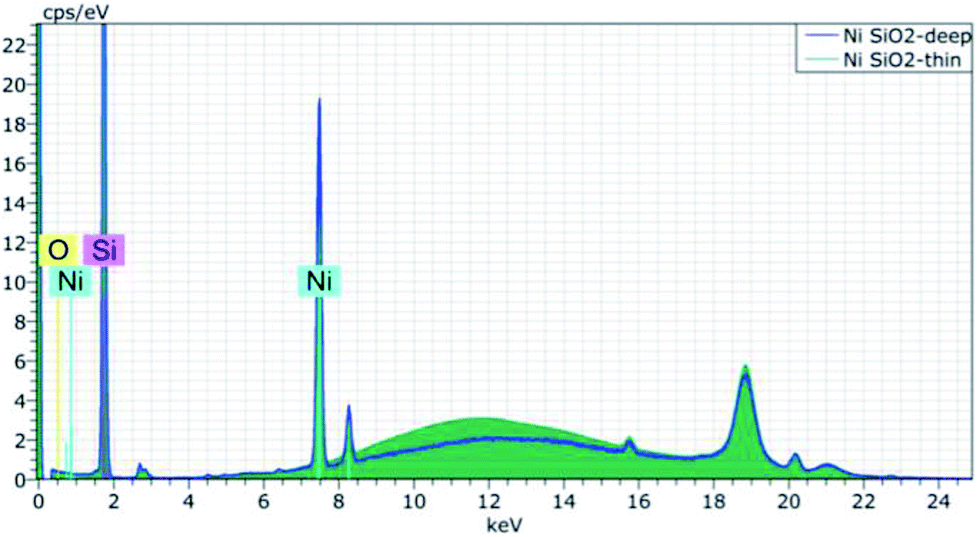 | ||
| Fig. 1 Ni/SiO2 XRF spectrum in a deep well (3 mm – blue curve) and in a shallow well (1 mm – green curve). | ||
It is worth mentioning that the anode element in the M4 XRF instrument (e.g., Rh or W) only affects the sensitivity for specific elements and not the information depth. Whereas the sensitivity depends on the number of photons above the absorptions edge of a given elements, the excitation of atoms is mainly governed by their absorption coefficient, which strongly depends on the photon energy.
For XRD, the penetration depth depends on the anode or X-rays tube wavelength and the sample composition. In order to evaluate this depth, calculations for 3 different X-rays wavelengths and different sample matrices were done. The choice of matrices is the same as for XRF study. AbsorbDX (Diffrac EVA V4.0) is used for this evaluation. The theory equations behind the software rely on the fact that, beside the scattering of X-rays, these latter are mainly absorbed by photoelectric effect. The X-rays attenuation in the samples follows the Beer–Lamberts laws and depends on the absorption coefficient of the sample and the X-rays wavelength (as for XRF). In a BBG, the thickness should be infinite for calculation of the intensity.16 To calculate the depth of the layer analyzed by X-rays, the chemical composition of the sample, its density, the anode element (Cu, Mo, Ag), the angle of incidence and the type of goniometer used (Bragg–Brentano) should be input in the software. Fig. 2 gathers the results of the penetration depth for the 3 anodes in 4 materials.
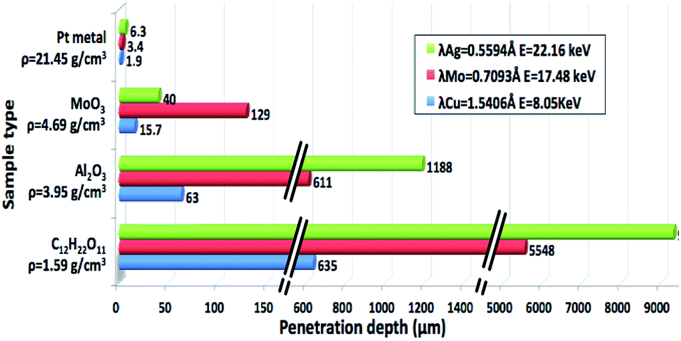 | ||
| Fig. 2 Penetration depth calculated for 3 different wavelengths in 4 matrices for XRD analysis. | ||
Fig. 2 shows that when the wavelength decreases, the penetration depth into the matter increases. Besides, X-rays penetrate deeper in light matrices than in heavy ones. For example for Ag anode, the penetration depth is around 9 mm when analyzing organic matrix. The D8 XRD device is equipped with a Cu anode. According to the results presented in Fig. 2 in the case of Cu, all the types of matrices, even the organic ones, can be accurately analyzed in a sample holder of 1 mm depth.
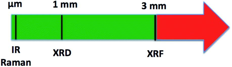
In summary, the probing depth for IR and Raman is at the micron scale for opaque powder catalysts. The sample holder depth is mainly constrained by the penetration depth of techniques that involve X-rays (Fig. 3). For XRD, a well depth of 1 mm is enough for all types of matrices when using a Cu anode. As already mentioned, XRF analysis requires a several mm depth of the sample for a quantitative analysis. But, as the quantity of catalyst synthesized is often restricted, a 3 mm depth for the sample holder was chosen and validated by the analysis of a light catalyst matrix (Ni/SiO2). This depth will enable the analysis of a wide range of heterogeneous catalysts. Only those composed of heavy compounds dispersed in an organic matrix will not be accurately analyzed (Table 1). For those catalysts (red zone in Fig. 3), Inductively Coupled Plasma (ICP) must be used to get accurate results of elemental analysis.
 | ||
| Fig. 3 Summary of the minimal penetration depth required for the 4 considered techniques. | ||
3.2 Spot size and well diameter
For the design of the shape of the well, it is very important to clearly identify the region of the sample which is probed, or, in other words, the volume of sample that is excited by the electromagnetic radiations and/or the volume from which the radiations are collected. The intensity of the source and the optical configuration of the instruments define the spot size on the sample. In this section, the spot size will be discussed separately for each instrument.The polychromatic IR beam coming from the source passes through a diaphragm, an interferometer and a focal mirror before reaching the surface of the sample. Finally, it is reflected towards the detector. The focal length of the mirror before the interferometer is 100 mm and that of the module HTS-XT is 51 mm, hence the spot size on the sample is about half the size of the source diaphragm (Fig. 4). The maximum aperture for the diaphragm is 6 mm. Thus, the circular spot size is half of it, which is about 3 mm. For powder catalyst analysis, a diaphragm aperture of 2.4 mm is usually used leading to a 1.2 mm circular diameter illuminating the sample.
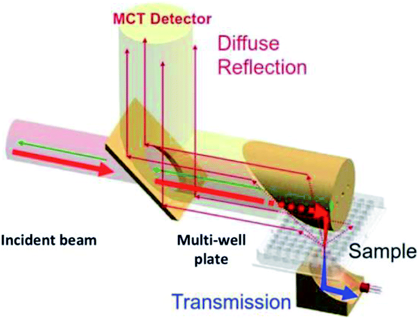 | ||
| Fig. 4 Optic used in reflection and transmission mode for IR on a multi-well plate (© Bruker). | ||
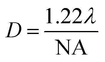
In Raman spectroscopy, the incident monochromatic light is inelastically scattered from a sample. When using a confocal Raman microscope, a very small sample area or volume, down to the micron scale, is analyzed. According to physics and under ideal conditions, the theoretical laser spot size is expressed as a function of the laser wavelength and the microscope objective magnification following the equation:17
 | ||
| Fig. 5 Spot diameter calculation for three lasers' excitations (λ = 532, 638 and 785 nm) and three objective types. | ||
Fig. 5 shows that the spot size increases when the wavelength increases. Note that using the objective with the smallest magnification (×10) results in relatively high spot diameters. For this technique, the larger spot size is less than 4 μm. At the μm scale, there is no constraint on the sample size for the well design.
For μ-XRF spectroscopy, the spot size is determined by the X-rays optics. In the Tornado M4, a poly-capillary optic is used with the Rh source. The capillary is a special type of total reflection optics. Poly-capillary optic is composed of a bundle of very thin single capillaries (inner diameter down to 1–2 μm each). All the capillaries are facing the source and collecting its primary radiation. They shape the beam and concentrate it to two small circular spots down to 20 μm or 200 μm diameter. During experiment, the choice of the spot size (20 or 200 μm) can be made, by the software, according to the sample size. For catalyst analysis, a 200 μm spot size is always selected in order to collect the maximum information on the sample. For the W source, a collimator is used. The collimator absorbs all the radiations that did not meet the collimator hole. However, these radiations penetrate the collimator without any changes in energy distribution. The spot size of a collimator is given by the diameter of the collimator. This size is limited by the captured solid angle of source radiation. For the Tornado M4, the spot size for the collimator is around 1 mm of diameter. Considering the two optics for XRF, collimator optic has the larger spot on the sample. Therefore, the diameter of the sample should be larger than 1 mm.
In reflection mode for XRD, X-rays generated by the source are shaped by the optics used on the diffractometer. The shape of the spot size is rectangular: the x value is defined by the divergence slit with motorized aperture and the y value can be controlled by the axial slit size (primary optic mounted on the anode). The motorized divergence slits keep the same illumination of the sample at all the angles to ensure a constant-surface condition. The larger the irradiated area, the greater the peak intensity. Therefore, the optimization of the X-rays spot size should be maximized on the whole sample area. The D8 XRD have a BBG that employs the θ:θ configuration: where the sample is stationary but the X-rays source and the detector are mounted on the goniometer arms that rotate around a common axis located at the goniometer center. The movements of X-ray source and detector arms are synchronized and have the same speed ensuring that the angles they form with the surface of the sample are decreased and increased equally. The goniometer center coincides with the measuring circle of the BBG. The sample should be located in the goniometer center and lies at a tangent to the focusing circle. Therefore, the sample surface must be rigorously flat. To be able to set the x and y coordinates of wells in the middle of the goniometer, each well was filled with scintillators ZnS:Cu (Fig. 6). Under the beam, a green light emission is induced enabling observation of the X-rays spot and each well position could then be adjusted in the center of the goniometer (Fig. 6). The z coordinates were set by matching the lines position of the standard reference silicon powder (NIST) with the Powder Diffractometer Files (PDF) from ICDD database.
 | ||
| Fig. 6 Analysis of ZnS:Cu on XRD to set the coordinates of each well in the center of the goniometer. | ||
The wells coordinates are registered in the software as a template. For automatic XRD analysis, the motorized plate places each well at the goniometer center according to the coordinates set in the software. On the other hand, to adjust the sample illumination, depending on the shape of the sample holder, the apertures of optics mounted on the tube were adjusted:
- Divergence slit with motorized aperture was optimized to fit in the center of the well: 8 mm (defines the x position);
- Slit optimized to fit in the center of the well: 8 mm (defines the y position);
- The square 8 mm × 8 mm is centered in the middle of the well and correspond to the maximum area illuminated by X-rays without touching the outer border of the well.
By analyzing the above constraints, the spot size for Raman is in the micron scale, while IR and XRF spot sizes are in the millimeter scale. The XRD spot size is optimized to 8 × 8 mm (Fig. 6) that guarantees high peaks intensity for catalyst analysis. The well diameter should then be optimized according to XRD, which imposes the largest one. The diameter of the circular well was hence set to 13.5 mm to include the XRD spot size. This diameter for the sample holder was also suitable for the other techniques as shown on Fig. 7.
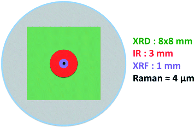 | ||
| Fig. 7 Circular well (in gray) with schematic representation of the spot shapes for the four different characterization techniques used. | ||
3.3 Multi-well plate material
The material chosen for the fabrication of the multi-well plate must be compatible with the XRD, XRF, IR and Raman analyses. Metallic well-plates were excluded because diffraction or photoelectric effect can occur if the beam reaches the well-plate bottom. This would interfere with the sample. On the other hand, as Raman and IR for powder catalysts' testing are surface-probing methods (penetration depth in the order of few microns), polymers can be used for the design of the well plate. Kapton was discarded because of the difficulty to use it in the fabrication process. Poly-methyl-methacrylate (PMMA) was chosen as material for the fabrication of the new versatile multi-well plate due to: (i) its amorphous structure18 (no parasite peak on XRD diffractogram), (ii) the energy of low atomic number elements constituting the PMMA which is undetectable by XRF, (iii) its ease to use in the machining process, and (iv) its low cost.3.4 Global design
Based on the different observations reported above, the design of the multi-well plate was chosen to be composed of individual wells that can be anchored on the flat surface of a plate. This design was chosen for two reasons: (i) individual wells can be filled independently from each other hence avoiding any possible cross contamination between the samples and (ii) a perfectly flat surface is needed for XRD analysis in BBG (see Section 3.2). The choices for the new design and the plate components are detailed in the following sub-sections.As aforementioned, the well diameter is chosen according to the XRD spot size. The internal diameter of the well is thus 13.5 mm to support the largest spot size of XRD (8 × 8 mm). As for the well depth, it is chosen according to XRF and XRD penetration depths. Three conditions contributed to the design of the depth: (a) XRD needs a large area of sample, but a 1 mm thickness is enough, (b) for XRF the analyzed sample area can be chosen by the operator, but XRF requires a few millimeters depth to guaranty accurate results for quantification and (c) small amount of catalysts are generally available. Combining these 3 conditions, a double depth well was designed. A 1 mm depth over the 13.5 mm diameter and in the middle of the circular well a 3 mm depth over 6 mm diameter (Fig. 8). This design enables accurate results for XRD for all types of catalysts. For automatic analysis by XRF, the multi-point mode is very often used. It consists of choosing the zone, the number and the coordinates of each point (200 μm each) prior to each analysis. By choosing to analyze the points in the center of the well (over the 3 mm depth zone), accurate results are obtained even when quantifying some catalysts composed of heavy elements in a light matrix. Furthermore, the double thickness enables limiting the amount of powder catalyst needed to fill the well (around 50 to 80 mg per well depending on the powder density).
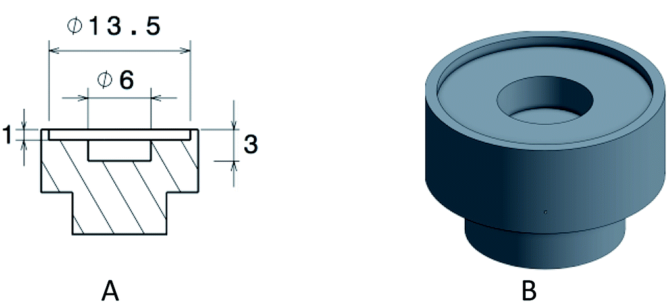 | ||
| Fig. 8 (A) Design of the well with its dimensions in mm, (B) 3D view of the well. | ||
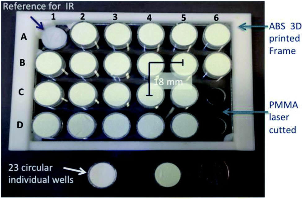 | ||
| Fig. 9 The multi-well plate, its components and coordinates. | ||
For analysis, each well is filled with powder catalyst. The top loading of each well is very important in order to have a perfectly horizontal surface for XRD. Then, the wells are inserted on the PMMA plate and analyzed by the four non-destructive methods of characterization. Thus, one plate preparation can be used to carry out four different analyses on four different instruments successively, collecting important information on the catalyst properties in a very limited amount of time.
3.5 Evaluation of the plate flatness by XRD
As mentioned before, in the Bragg–Brentano geometry, the sample surface is tangent to the focusing circle. Therefore, the surface of the sample must be rigorously flat. Obviously, the plate flatness is evaluated on XRD which is the most sensitive technique on that point. In fact, when top-loading the sample, the displacement error is difficult to avoid. This error combines the error of filling the wells and the flatness of the plate surface. It is described in Fig. 10, which represents the difference between the reference level (optimized Z position = goniometer center) and the sample surface leading to a shift in 2θ on the diffractogram of the sample. | ||
| Fig. 10 Displacement error description (height error in μm). | ||
To test the new design of the plate, its 23 wells were filled with calcined Y2O3 and analyzed by XRD. Y2O3 was chosen because of the presence of peaks at low and high angles on the diffractograms. Thus, the shift of peaks can be representative for a wide range of samples. Fig. 11 shows all the diffractograms overlaid and presenting a shift in 2θ position. For this study a middle angle (2θ = 29.14°) was chosen to show the shift of diffractograms collected on the 23 positions of the plate (Fig. 11A).
 | ||
| Fig. 11 Representation of the shift (A) and the correction of the peak (B) for the XRD analysis of Y2O3. | ||
The shift is corrected for each well according to the reference (given by the PDF) in red (Fig. 11B). The maximum shift corresponds to 0.13°. By correcting the shift in degrees, the software Diffrac EVA V4.0 evaluates the displacement error in μm.
This displacement is reported for the 23 wells to visualize the error of flatness of the entire plate. Rows B and C have the lowest error. Row D shows a positive error contrarily to row A (Fig. 12). However, all errors have led to a shift in 2θ position less than 0.2°, which is an acceptable limit for identification in XRD. Therefore, this good result validates the multi-well plate on the most demanding instrument (XRD device).
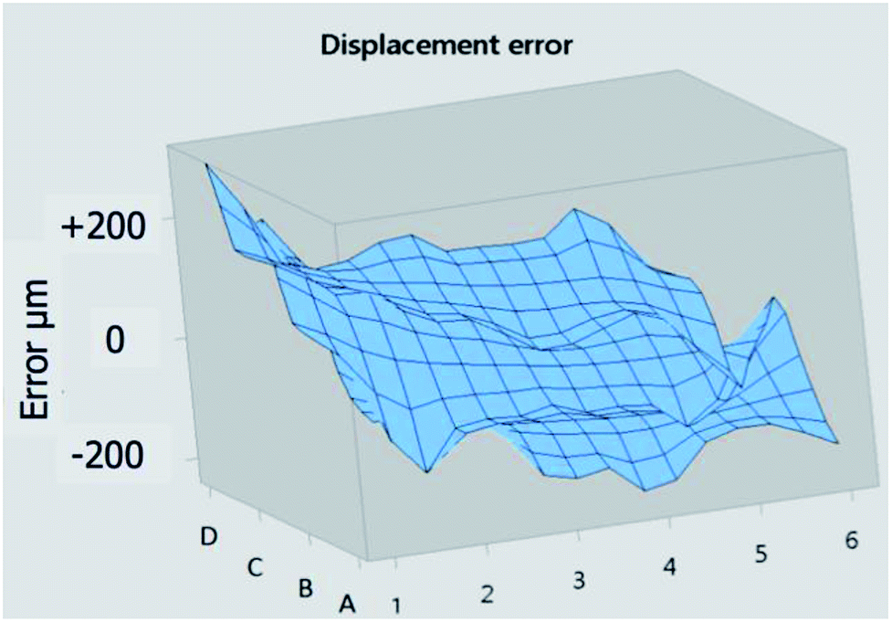 | ||
| Fig. 12 Displacement error in μm represented in 3D. | ||
4 Conclusions
This paper details the methodology adopted (based on interaction between light and matter) and also the constraints to be taken into consideration for the design of any multi-well plate. In the case of REALCAT platform, the multi-well plate constraints were evaluated for the four instruments according to their respective penetration depths, spot sizes, number and the designs of the well holders and optics. Table 2 summarizes the constraints that imposed the well design.| XRD | XRF | FTIR | Raman | |
|---|---|---|---|---|
| Penetration depth | 1 mm | 3 mm | μ Scale | μ Scale |
| Spot size | 8 × 8 mm | 1 mm diameter | 3 mm diameter | μ Scale |
| Plate size and dimension | Optimized template | No constraint | Optic alignment | No constraint |
The depth of the well is chosen according to X-rays method, the spot size is chosen according to XRD and the plate design according to IR. Raman, a surface probing technique and a focusing method, did not imply any constraint on the design of the well plate.
The multi-well was validated on the XRD, XRF, IR and Raman instruments but this paper highlights results obtained on X-rays techniques that were the most restrictive on the design.
This new versatile multi-well plate enables rapid, systematic and automatized characterization of powder catalysts using 4 different HT techniques in the reflection mode. This plate meets the constraints of spectroscopic techniques including the X-rays ones, which are the most stringent. The major features of this new multi-well plate are as follows: (i) 23 individual wells, which are easy to fill reliably and quickly with a flat surface, (ii) easy sample filling without cross-contamination, (iii) small quantities of catalyst needed (50 to 80 mg) and (iv) compatible and convenient for HT experimentation.
Finally, the preparation of one well plate for 4 characterization techniques led to a significant gain of time and resources, a very important factor when working in a high-throughput environment.
Conflicts of interest
REALCAT is the name of a research project including a platform financed by the French Government and run by the University of Lille. The multi-well plate is designed purely for research and is not considered for patent application or for sale.Acknowledgements
The authors gratefully acknowledge the support of the French National Research Agency (ANR-11-IS09-0003 and ANR-12-BS07-0029). The REALCAT platform is benefiting from a state subsidy administrated by the French National Research Agency (ANR) within the frame of the ‘Future Investments’ program (PIA), with the contractual reference ‘ANR-11-EQPX-0037’. The European Union, through the ERDF funding administered by the Hauts-de-France Region, has co-financed the platform. Centrale Lille, the CNRS, and Lille University as well as the Centrale Initiatives Foundation, are thanked for their financial contributions to the acquisition and implementation of the equipment of the REALCAT platform. Chevreul Institute (FR 2638), Ministère de l’Enseignement Supérieur, de la Recherche et de l’Innovation are acknowledged for supporting and funding partially this work. The authors would like to thank Mr Christophe Vermander for the well's machining and Mr Simon Thomy for helping cutting the plate by laser.Notes and references
- B. Jandeleit, D. J. Schaefer, T. S. Powers, H. W. Turner and W. H. Weinberg, Angew. Chem., Int. Ed., 1999, 38, 2494 CrossRef CAS PubMed.
- S. Paul, S. Heyte, B. Katryniok, C. Garcia-Sancho, P. Maireles-Torres and F. Dumeignil, Oil Gas Sci. Technol., 2015, 70(3), 455 CrossRef CAS.
- Z. Ma and F. Zaera, Characterization of Heterogeneous Catalysts, 2006, ch 1, DOI:10.1201/9781420015751.ch1.
- N. E. Tsakoumis, A. P. E. York, D. Chen and M. Rønning, Catal. Sci. Technol., 2015, 5, 4859 RSC.
- J. M. Palmer, Handbook of Optics: Devices, Measurements, and Properties, Volume II, 1995, ch 25 Search PubMed.
- F. Zaera, Chem. Soc. Rev., 2014, 43, 7624 RSC.
- C. Mondelli, V. D. Santo, A. Trovarelli, M. Boaro, A. Fusi, R. Psaro and S. Recchia, Catal. Today, 2006, 113, 81 CrossRef CAS.
- N. Everall, Spectroscopy, 2004, 19, 10 Search PubMed.
- S. J. Tinnemans, M. H. F. Kox, M. W. Sletering, T. A. Nijhuis, T. Visser and B. M. Weckhuysen, Phys. Chem. Chem. Phys., 2006, 8, 2413 RSC.
- S. Kumar, F. Carniato, A. Arrais, G. Croce, E. Boccaleri, L. Palin, W. van Beek and M. Milanesio, Cryst. Growth Des., 2009, 9(8), 3396 CrossRef CAS.
- J. Song, C. Yang, H. Hu, X. Dai, C. Wang and H. Zhang, Sci. China: Phys., Mech. Astron., 2013, 56(11), 2065 CAS.
- V. Thomsen, Spectroscopy, 2007, 46(22), 5 Search PubMed.
- V. Thomsen, D. Schatzlein and D. Mercuro, Spectroscopy, 2005, 20(9), 22 CAS.
- R. Sitko, Spectrochim. Acta, Part B, 2009, 64, 1161 CrossRef.
- R. Rousseau and J. Boivin, Rigaku J., 1998, 15, 1 Search PubMed.
- L. B. McCusker, R. B. Von Dreele, D. E. Cox, D. Louër and P. Scardi, J. Appl. Crystallogr., 1999, 32, 36 CrossRef CAS.
- F. Adar, E. Lee, S. Mamedov and A. Whitley, Microsc. Microanal., 2010, 16(suppl 2), 360 CrossRef CAS.
- E. Shobhana, International Journal of Modern Engineering Research, 2012, 2(3), 1092 Search PubMed.
| This journal is © The Royal Society of Chemistry 2018 |