 Open Access Article
Facile synthesis of highly conductive MoS2/graphene nanohybrids with hetero-structures as excellent microwave absorbers†
Jixing Chai‡
ab,
Deqing Zhang‡*ab,
Junye Chengcd,
Yixuan Jiab,
Xuewei Bab,
Ya Gaoe,
Lei Zhuf,
Hao Wang*c and
Maosheng Cao *g
*g
aHeilongjiang Provincial Key Laboratory of Polymeric Composite Materials, Qiqihar University, Qiqihar 161006, China. E-mail: zhdqing@163.com
bSchool of Materials Science and Engineering, Qiqihar University, Qiqihar 161006, China
cGuangdong Provincial Key Laboratory of Micro/Nano Optomechatronics Engineering, College of Mechatronics and Control Engineering, Shenzhen University, Shenzhen 518060, China. E-mail: whao@szu.edu.cn
dCenter of Super-Diamond and Advanced Films, Department of Materials Science and Engineering, City University of HongKong, HongKong 999077, China
eSchool of Chemistry and Chemical Engineering, Qiqihar University, Qiqihar 161006, China
fSchool of Communication and Electronic Engineering, Qiqihar University, Qiqihar 161006, China
gSchool of Materials Science and Engineering, Beijing Institute of Technology, Beijing 100081, China. E-mail: caomaosheng@bit.edu.cn
First published on 31st October 2018
Abstract
Two-dimensional (2D) MoS2/graphene nanosheet (MoS2/GN) hybrids have been demonstrated to be promising microwave absorption (MA) materials due to their unique chemical and physical properties as well as rich impedance matching. However, the reported strategies for preparing MoS2/GN hybrids have limited their application potential due to the complex, high-cost and inefficient preparation processes. On the other hand, it is of note that the main source of graphene is based on converting insulating graphene oxides (GO) back to conductive reduced graphene oxides (RGO). Thus, the MA performance of obtained MoS2/RGO nanohybrids is greatly affected by the conversion process of GO. In this work, we prepared the MoS2/GN hybrids by a facile hydrothermal method with directly introducing highly pure and electroconductive GNs. It is found that the highest reflection loss value of the sample-wax containing 40% MoS2/GN is −57.31 dB at a thickness of 2.58 mm, and the bandwidth of RL values less than −10 dB can reach up to 12.28 GHz (from 5.72 to 18 GHz) when an appropriate absorber thickness between 1.5 and 4 mm is chosen. The excellent MA performances emanate from effective conjugation of MoS2 with GN (Mo–C bond between the interfaces), which provides the dielectric loss caused by multi-relaxation, conductance, and polarization. Taking into account the facile synthesis route and their excellent MA performance, the MoS2/GNs hybrid nanosheets and those composite materials with similar isomorphic hetero-structures are very promising for a wide range of MA applications.
1. Introduction
With more and more electronic communication devices around us, the resulting electromagnetic pollution is becoming a threat to human beings. Therefore, designing and preparing efficient microwave absorbing (MA) materials is crucial to governing electromagnetic pollution.1–6 Two-dimensional (2D) materials, specially molybdenum disulfide (MoS2), have attracted attention as MA materials due to their size effect, high specific surface areas and remarkable mechanical properties.7–11 However, the further application of pure MoS2 is limited by narrow bandwidth; low RL value and the poor impedance matching of single component materials.12–15Therefore, one of the strategies is introducing a second phase, such as magnetic ferrite (Fe3O4),16,17 carbon materials (CNT, GN),18,19 and conductive polymers (PEDOT),20,21 into/onto the matrix to improve the MA performance and enrich impedance matching.22–24 Zhang et al.25 synthesized MoS2/Fe3O4 hybrids through a hydrothermal and coprecipitation method and they exhibited outstanding MA performance. Pan et al.26 reported a porous coin-like Fe@MoS2 composite which optimized impedance matching and showed efficient microwave absorption. Zhang et al.27 fabricated MoS2/PANI-NDs composites via an in situ oxidation polymerization which exhibited tunable electromagnetic wave attenuation performance. Liu et al.28 prepared 3D hierarchical MoS2 nanosheets/ultralong N-doped carbon nanotubes as a high-performance electromagnetic wave absorbing material.
Among these second phase materials, graphene shows great potential due to its exclusive structures and electrical properties. Wang et al.29 first synthesized MoS2/RGO hybrids by chemical vapor deposition and the highest reflection loss value is −50.9 dB. Ran et al.30 reported the synthesis of MoS2/RGO hybrids by a three-step ultrasonic method and that the highest reflection loss value was −49.7 dB. It should be noted that the preparation of MoS2/graphene hybrids with hetero-structures involves the conversion of insulating GO into conductive RGO using reducing agents or high-temperature thermal annealing treatments.31,32 The conversion process is usually tedious and with some troubles, such as insufficient conductivity recovery, morphological changes, phase transitions, even samples polluted with reducing agents. And the reported preparation of MoS2/graphene hybrids with pure GNs is inefficient and high-cost, which is not viable from the viewpoint of practical application.
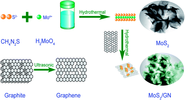
In this work, we develop a hydrothermal method to prepare dielectric MoS2-nanosheets (MoS2-NS) and MoS2/GN hybrids with hetero-structures, using molybdic acid; thiourea to grow on pure GN (Scheme 1). This synthesis strategy for MoS2 and MoS2/GN hybrids could be applied in various research areas including catalysis, environmental remediation and hydrogen evolution. The as-synthesized MoS2/GN hybrids show efficient MA performance, and we also investigate the MA performance mechanisms of MoS2/GN hybrids.
2. Experimental
All chemicals were in analytical grade and used without further purification. Molybdic acid (H2MoO4 ≥ 85%) was purchased from Shanghai Aladdin Biochemical Technology Co. Ltd. Thiourea (CH4N2S) was purchased from Tianjin Fuchen Chemical Reagent Factory. Natural graphite powders were purchased from Qingdao YUBO graphite Technology Co, LTD. Deionized water was purchased from Qiqihar Tianyuan Water Supply Company.Graphene was prepared from graphite power by a liquid-phase ultrasound method.15 MoS2/GN hybrids were prepared by an improved one-step hydrothermal method. Firstly, 40 mg graphene-nanosheets (GN) was dispersed in 40 mL of ethanol/deionized water mixture (volume ratio: 1/3). Secondly, 0.4 g H2MoO4 and 0.75 g CH4N2S were added into the above dispersions. After magnetic stirring for 30 min, the mixture was transferred to a 100 ml Teflon-lined autoclave with a magnetic stirring device. After heated and stirred for 10 hours at 200 °C, the mixtures were subsequently cooled down to room temperature at natural circumstances. Finally MoS2/GN hybrids were washed with deionized water and ethanol for several times and dried at 60 °C under vacuum oven.
The morphology of samples was characterized by transmission electron microscope (TEM: Japan Hitachi H7650). The crystallization properties were investigated by an X-ray diffractometer (Bruker Company, D8) using the Cu-Kα radiation (λ = 0.15418 nm). The crystal structure of samples was further observed with high-resolution electron microscopy (HRTEM: Tecnai F30). X-ray photoelectron spectra (XPS) were recorded using a Thermo Scientific ESCALAB MK II with an Mg Kα excitation source. Raman spectroscopy measurements were performed via a Lab RAM HA Evolution. The complex permittivity and permeability were measured in a frequency range of 2–18 GHz with a coaxial wire method using an Agilent N5244A network analyzer.
3. Results and discussion
The XRD patterns of GN; MoS2 and MoS2/GN are shown in Fig. S1† and 1a. The MoS2-nanosheets show diffraction peaks at 2θ = 14.6°, 32.8°, 39.8° and 58.5° corresponding to the (002), (100), (103), and (110) planes (PDF37-1492). It is worth noting that there are no diffraction peaks for GN at the patterns of MoS2/GN hybrids, suggesting the weak scattering power and low crystallinity of very small amount of GNs added. However, the existence of GNs in the hybrid could be identified by Raman spectroscopy (Fig. 1b). There are two strong peaks located at 1345 and 1587 cm−1, which correspond to the D- and G-bands for GNs. It is also observed that the weak E2g and A1g peaks for MoS2 are located at 376 and 405 cm−1.29 In general, the number of layers of graphene is usually determined by the 2D/G ratios. In this work, the 2D/G ratio of MoS2/GN hybrids is 0.21 (0.07 < 0.21 < 0.3), corresponding to triple-layer graphene sheets,33 which consistent with pure GN (as shown in Fig. S2†).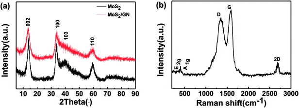 | ||
| Fig. 1 (a) X-ray powder diffraction (XRD) patterns for MoS2 and MoS2/GN; (b) Raman spectrum for MoS2/GN. | ||
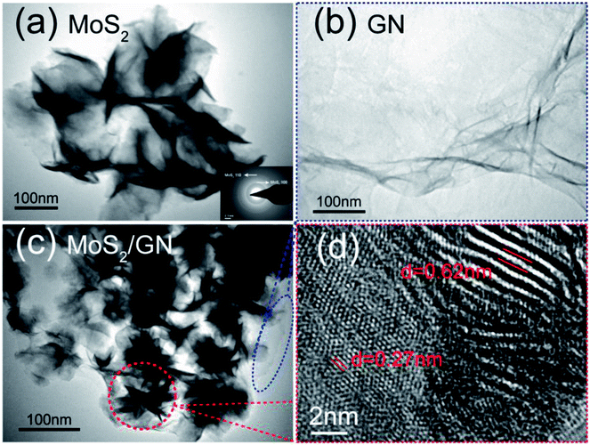
Typical morphology information of the MoS2/GN hybrids is obtained by TEM. Fig. 2a shows that 2D MoS2 nanosheets look like a flexible flower. The corresponding selected area electron diffraction (SAED) patterns of the MoS2-nanosheets are also presented in the inset of Fig. 2a, two diffraction rings in the SAED patterns agree well with the (110) and (100) planes of MoS2. Fig. 2b shows that GN looks thin and light. The overall morphology image of MoS2/GN hybrids is shown in Fig. 2c. As presented, it can be clearly seen that the flower-like MoS2-NS are evenly attached on the GNs. The further micromorphology information of MoS2/GN composites is displayed by HRTEM, and the interplanar spacing of 0.62 and 0.27 nm observed in Fig. 2d are corresponding to the (002) and (100) planes of hexagonal MoS2 crystalline structure.22,34
The MoS2/GN hybrids were also characterized by X-ray photoelectron spectroscopy (XPS). As shown in Fig. 3a, there are only the Mo, S, C and O elements in the survey spectrum, and the atomic contents of Mo and S are 15.52% and 31.76%, respectively. The ratio of Mo/S is very close to 1![[thin space (1/6-em)]](https://www.rsc.org/images/entities/char_2009.gif) :
:![[thin space (1/6-em)]](https://www.rsc.org/images/entities/char_2009.gif) 2. The Mo spectrum for MoS2/GN as shown in Fig. 3b, the bands located at binding energies of 232.05 and 228.75 eV were assigned to the Mo (3d3/2) and Mo (3d5/2) in the normal state of Mo4+ chemical state, respectively. Moreover, the peak deconvolution of the Mo (3d) spectrum of the MoS2/GN hybrids indicated two other weak peaks located at 233.00 and 229.20 eV which were attributed to formation of a Mo–C bond on the hybrids, that is, formation of MoS2/GN hetero-structures. That shows during the prepared process some carbon diffused into the MoS2 to substitute in the lattice of MoS2 at the interfaces.35–37 The S spectrum of MoS2/GN can be observed to have two peaks located at 162.82 and 161.71 eV, as shown in Fig. 3c, in consistent with the existence of MoS2. The C 1s spectrum can be deconvoluted into two peaks located at 285.30 and 284.47 eV (Fig. 3d), which correspond to the C–N and C–C functionalities, respectively. Moreover, the band located at 283.90 eV was assigned to the presence of the Mo–C bond, which also proved the formation of hetero-structures.
2. The Mo spectrum for MoS2/GN as shown in Fig. 3b, the bands located at binding energies of 232.05 and 228.75 eV were assigned to the Mo (3d3/2) and Mo (3d5/2) in the normal state of Mo4+ chemical state, respectively. Moreover, the peak deconvolution of the Mo (3d) spectrum of the MoS2/GN hybrids indicated two other weak peaks located at 233.00 and 229.20 eV which were attributed to formation of a Mo–C bond on the hybrids, that is, formation of MoS2/GN hetero-structures. That shows during the prepared process some carbon diffused into the MoS2 to substitute in the lattice of MoS2 at the interfaces.35–37 The S spectrum of MoS2/GN can be observed to have two peaks located at 162.82 and 161.71 eV, as shown in Fig. 3c, in consistent with the existence of MoS2. The C 1s spectrum can be deconvoluted into two peaks located at 285.30 and 284.47 eV (Fig. 3d), which correspond to the C–N and C–C functionalities, respectively. Moreover, the band located at 283.90 eV was assigned to the presence of the Mo–C bond, which also proved the formation of hetero-structures.
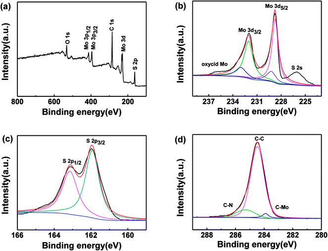 | ||
| Fig. 3 XPS spectra of the MoS2/GN samples: overall spectrum as marked (a); Mo 3d (b); S 2p (c); C 1s (d). | ||
The MA performance can be evaluated by the values of reflection loss (RL) versus frequency which can be determined according to transmission line theory.38–41 The RL is calculated with the following formulas:
 | (1) |
 | (2) |
Fig. 4 shows the RL curves of MoS2–wax composites and MoS2/GN–wax composites with different loading contents (from 30 to 50 wt%) in the frequency range of 2–18 GHz at the thickness of 2.5 mm. It can be found that under the same loading of 40 wt%, the value of RL for MoS2/GN hybrid (−43.68 dB) is much larger than that of pure MoS2 (−19.83 dB). For the MoS2/GN-wax composites, it can be found that the MA performance of MoS2/GN-wax composites improves with the increasing loading of MoS2/GN from 30 to 40 wt%. Nevertheless, degraded MA performance is also observed for the sample with the MoS2/GN loading of 50 wt%. In summary, the MoS2/GN–wax composites containing 40 wt% loading exhibited the outstanding microwave absorption properties.
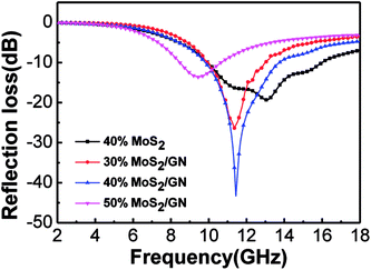 | ||
| Fig. 4 RL curves of MoS2 and MoS2/GN composites mixed with paraffin with different loading (thickness: 2.5 mm, frequency: 2–18 GHz). | ||
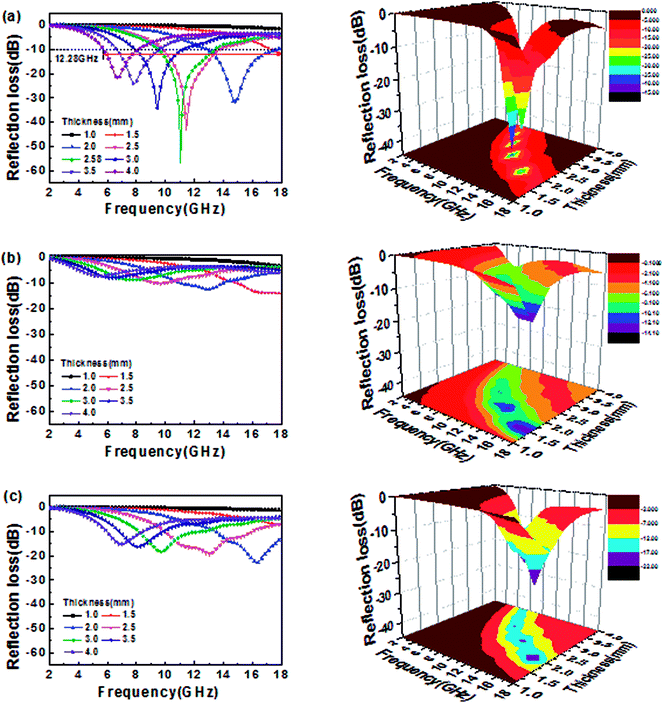
Fig. 5 shows the RL value and 3D plots for MoS2–wax composites, GN–wax composites and MoS2/GN–wax composites with different thickness (40 wt% loading). The minimum RL is observed to be −57.31 dB at 11.03 GHz for MoS2/GN with a thickness of 2.58 mm; the bandwidth of RL values less than −10 dB can reach up to 12.28 GHz (from 5.72 to 18 GHz) when an appropriate absorber thickness between 1.0 and 4 mm is chosen (as shown Fig. 5a). Compared with the MoS2/GN hybrids, the MoS2-NS and GN-NS exhibit poor MA performances (Fig. 5b and c), indicating that the combination of MoS2 with GN is an effective method in improving the MA performance.
The permittivity and permeability of MoS2 and MoS2/GN with 40 wt% loadings were investigated to better understand the probable mechanism of dielectric loss or magnetic loss. Fig. 6 shows the complex permittivity; complex permeability and dielectric loss tangents (tan![[thin space (1/6-em)]](https://www.rsc.org/images/entities/char_2009.gif) δe = ε′′/ε′) of MoS2 and MoS2/GN hybrid in the range of 2–18 GHz. Obviously, as shown in Fig. 6a, both real (ε′) and imaginary (ε′′) permittivity of MoS2/GN are found higher than that of pure MoS2, and both real ε′ and ε′′ decrease with increasing frequency. As shown in Fig. 6b, the values of μ′ and μ′′ for both MoS2 and MoS2/GN are low, and are close to 1 and 0, respectively. As shown in Fig. 6c, the dielectric loss tangent of MoS2/GN is higher than that of pure MoS2.
δe = ε′′/ε′) of MoS2 and MoS2/GN hybrid in the range of 2–18 GHz. Obviously, as shown in Fig. 6a, both real (ε′) and imaginary (ε′′) permittivity of MoS2/GN are found higher than that of pure MoS2, and both real ε′ and ε′′ decrease with increasing frequency. As shown in Fig. 6b, the values of μ′ and μ′′ for both MoS2 and MoS2/GN are low, and are close to 1 and 0, respectively. As shown in Fig. 6c, the dielectric loss tangent of MoS2/GN is higher than that of pure MoS2.
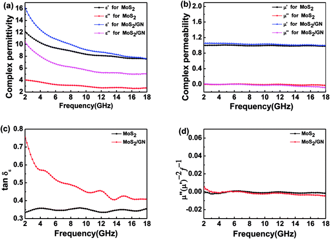 | ||
| Fig. 6 The complex permittivity (a); and complex permeability (b); the dielectric loss (c) and the values of C0 = μ′′(μ′)−2f−1 (d) in the range of 2–18 GHz for MoS2 and MoS2/GN composites. | ||
In general, the change of complex permittivity can be explained according to Debye theory:42–45
 | (3) |
 | (4) |
![[thin space (1/6-em)]](https://www.rsc.org/images/entities/char_2009.gif) 800 S m−1 and 109.5 S m−1, respectively. Compared to reported MoS2/RGO composites, the conductivity of MoS2/GN hybrids in this work is close to that of 30 wt% RGO addition amount of MoS2/RGO hybrids (113.3 S m−1) in the literature.13 The highly conductive MoS2/GN hybrids stem from the high electrical conductive GNs. According to the free electron theory,14 ε′′ = 1/2ε0πρf, where ε0, ρ and f are the permittivity of vacuum, the resistivity and the frequency of the electromagnetic wave, respectively. Therefore, the high electrically conductive GNs result in the enhanced ε′′ values of MoS2/GN. The μ′ and μ′′ for both MoS2 and MoS2/GN are low and no obvious changes appear due to lack of magnetic components in the composite-wax of MoS2 and MoS2/GNs. However, possible magnetic loss for MoS2 and MoS2/GN were also investigated. As shown in Fig. 6d, the value of μ′′(μ′)−2f−1 is almost a constant within the range of 4–18 GHz, indicating that the eddy current loss is the main contribution of the magnetic loss in MoS2 and MoS2/GN at 4.0–18.0 GHz.
800 S m−1 and 109.5 S m−1, respectively. Compared to reported MoS2/RGO composites, the conductivity of MoS2/GN hybrids in this work is close to that of 30 wt% RGO addition amount of MoS2/RGO hybrids (113.3 S m−1) in the literature.13 The highly conductive MoS2/GN hybrids stem from the high electrical conductive GNs. According to the free electron theory,14 ε′′ = 1/2ε0πρf, where ε0, ρ and f are the permittivity of vacuum, the resistivity and the frequency of the electromagnetic wave, respectively. Therefore, the high electrically conductive GNs result in the enhanced ε′′ values of MoS2/GN. The μ′ and μ′′ for both MoS2 and MoS2/GN are low and no obvious changes appear due to lack of magnetic components in the composite-wax of MoS2 and MoS2/GNs. However, possible magnetic loss for MoS2 and MoS2/GN were also investigated. As shown in Fig. 6d, the value of μ′′(μ′)−2f−1 is almost a constant within the range of 4–18 GHz, indicating that the eddy current loss is the main contribution of the magnetic loss in MoS2 and MoS2/GN at 4.0–18.0 GHz.
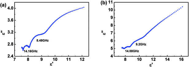
As presented, the MA performance of MoS2 and MoS2/GN are mainly determined by dielectric loss. In order to investigate and better understand the dielectric loss, the relationship between the relative complex permittivity is expressed by the equation:
 | (5) |
In this work, the excellent MA performance of MoS2/GN hybrid is ascribed to the following factors. First, as shown in Fig. 8a, the addition of GN adjusts the complex permittivity of MoS2 nanosheets, which facilitates impedance matching. Second, the additional GN also carries abundant defects (such as imperfect carbon for GN), providing a large number of dipoles, which are very helpful for dielectric relaxation. Meanwhile, the interfacial polarization in MoS2/GN, which is considered as the capacitor-like structure, could be effective in the adsorption of electromagnetic waves (Fig. 8b). It could be supported by the mechanism of multi-polarization reported by Cao et al.46 Third, electrons can absorb energy and leap on the composite nanosheets, resulting in eddy current losses (Fig. 8c). It also could be supported by Cao's Electron-Hopping model and Conductive–Network equation.47 Fourth, the multiple scattering also plays a significant role in electromagnetic wave attenuation as shown in Fig. 8d, the sandwiched layers could lead to the inter-layer reflection and continuous loss of electromagnetic waves. Fifth, the materials with good electrical conductivity may produce skin effect and additional reflection at the surface between materials and air,48 which offers effective electromagnetic attenuation.
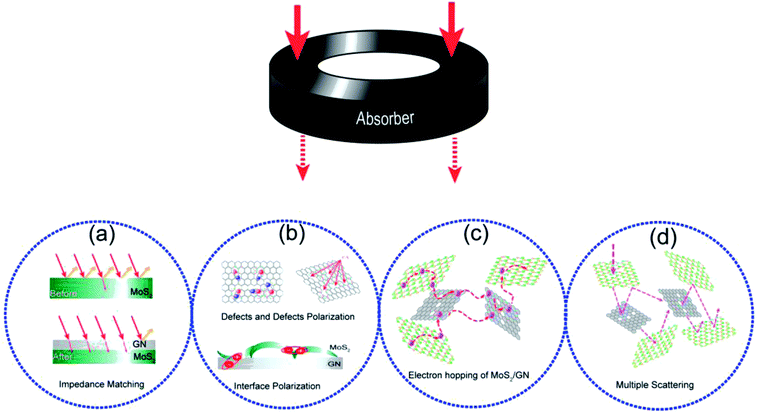 | ||
| Fig. 8 (a) Impedance matching of MoS2/GN; (b) defects and defects polarization of GN; interface polarization of MoS2/GN; (c) electron hopping of MoS2/GN; (d) multiple scattering of MoS2/GN. | ||
As listed in Table 1, compared with the previously reported MoS2/graphene MA materials, the minimum RL value of MoS2/GN hybrids in this work is higher than those of MoS2/RGO hybrids in previous reports. Meanwhile, it is also shown that the minimum RL value of MoS2/RGO prepared by chemical vapor deposition is higher than that of MoS2/RGO prepared by hydrothermal method. This is because the chemical vapor deposition can help convert more insulating GO back to conductive RGO.
| Method | Thickness (mm) | Minimum RL value (dB) | Loading ratio (wt%) | Effective bandwidth (GHz) | Ref. | |
|---|---|---|---|---|---|---|
| MoS2/GN | Liquid phase stripping, hydrothermal | 2.58 | −57.31 | 40 | 12.28 | This work |
| MoS2 | Hydrothermal | 2.0 | −22.85 | 40 | 4.5 | This work |
| MoS2 | Liquid phase stripping | 2.4 | −38.42 | 60 | 4.16 | 12 |
| MoS2/RGO | Hummers, chemical vapor deposition | 1.9 | −50.9 | 10 | 5.72 | 29 |
| MoS2/RGO | Hummers, hydrothermal | 2.5 | −41.53 | 10 | 5.92 | 13 |
| MoS2/RGO | Hummers, hydrothermal | 2.4 | −41.9 | 30 | 5.8 | 14 |
| M/MoS2/RGO | Hummers, liquid phase ultrasound | 2.5 | −49.7 | 18 | 5.81 | 30 |
| MoS2/GN | Liquid phase stripping, hydrothermal | 2.2 | −55.3 | 20 | 5.6 | 15 |
4. Conclusion
In summary, MoS2 and MoS2/GN hybrids were prepared by a facile one-step hydrothermal method, and the MoS2-nanosheets were conjugated on the highly conductive GNs. The mechanisms of MA performance for MoS2 and MoS2/GN were also investigated. The excellent MA performance indicates that the MoS2/GN hybrids with hetero-structures hold some advantages in both high conductance and high absorption performance devices. It is also believed that the simple hydrothermal method can promote the synthesis of hetero-structures nanohybrids at an industrial scale. Furthermore, the hetero-structure nanohybrids could also be readily applied in other fields.Conflicts of interest
There is no conflict in the statement.Acknowledgements
This work was supported by the National Natural Science Foundation of China (51272110, 51772160 and 51771123) and the Shenzhen Peacock Innovation Project (Grant No. KQJSCX20170327151307811).References
- W. L. Song, M. S. Cao, L. Z. Fan, M. M. Lu, Y. Li, C. Y. Wang and H. F. Ju, Carbon, 2014, 77, 130–142 CrossRef CAS.
- L. L. Yan, X. X. Wang, S. C. Zhao, Y. Q. Li, Z. Gao, B. Zhang, M. S. Cao and Y. Qin, ACS Appl. Mater. Interfaces, 2017, 9, 11116–11125 CrossRef CAS PubMed.
- W. L. Song, X. T. Guan, L. Z. Fan, W. Q. Cao, C. Y. Wang, Q. L. Zhao and M. S. Cao, J. Mater. Chem. A, 2017, 3, 2097–2107 RSC.
- B. Zhao, C. X. Zhao, M. Hamidinejad, C. D. Wang, R. S. Li, S. Wang, Y. Kazemi and C. B. Park, J. Mater. Chem. C, 2018, 6, 10292–10300 RSC.
- W. L. Song, X. T. Guan, L. Z. Fan, Y. B. Zhao, W. Q. Cao, C. Y. Wang and M. S. Cao, Carbon, 2016, 100, 109–117 CrossRef CAS.
- S. Motojima, S. Hoshiya and Y. Hishikawa, Carbon, 2003, 41, 2658–2660 CrossRef CAS.
- X. Liu, L. S. Wang, Y. T. Ma, H. F. Zheng, L. Lin, Q. F. Zhang, Y. Z. Chen, Y. L. Qiu and D. L. Peng, ACS Appl. Mater. Interfaces, 2017, 9, 7601–7610 CrossRef CAS PubMed.
- X. Sun, J. P. He, G. X. Li, J. Tang, T. Wang, Y. X. Guo and H. R. Xue, J. Mater. Chem. C, 2012, 1, 765–777 RSC.
- M. S. Cao, J. Zhu, J. Yuan, T. F. Zhang, Z. H. Peng, Z. J. Guo, G. Xiao and S. M. Qin, Mater. Des., 2002, 23, 557–564 CrossRef.
- M. Q. Zeng, Y. Xiao, J. X. Liu, K. N. Yang and L. Fu, Chem. Rev., 2018, 118, 6236–6296 CrossRef CAS PubMed.
- B. Zhao, L. Y. Liang, J. S. i. Deng, Z. Y. Bai, J. W. Liu, X. Q. Guo, K. Gao, W. H. Guo and R. Zhang, CrystEngComm, 2017, 19, 6579–6587 RSC.
- M. Q. Ning, M. M. Lu, J. B. Li, Z. Chen, Y. K. Dou, C. Z. Wang, F. Rehman, M. S. Cao and H. B. Jin, Nanoscale, 2015, 7, 15734–15740 RSC.
- X. Ding, Y. Huang, S. Li, N. Zhang and J. G. Wang, Composites, Part A, 2016, 9, 424–432 CrossRef.
- X. X. Wang, W. L. Zhang, X. Q. Ji, B. Q. Zhang, M. X. Yu, W. Zhang and J. Q. Liu, RSC Adv., 2016, 6, 106187–106193 RSC.
- D. Q. Zhang, Y. X. Jia, J. Y. Cheng, S. M. Chen, J. X. Chai, X. Y. Yang, Z. Y. Wu, H. Wang, W. J. Zhang, Z. L. Zhao, C. Han, M. S. Cao and G. P. Zheng, J. Alloys Compd., 2018, 758, 62–71 CrossRef CAS.
- X. H. Li, H. B. Yi, J. W. Zhang, J. Feng, F. S. Li, D. S. Xue, H. L. Zhang, Y. Peng and N. J. Mellors, J. Nanopart. Res., 2013, 15, 1472 CrossRef.
- G. B. Sun, B. X. Dong, M. H. Cao, B. Q. Wei and C. W. Hu, Chem. Mater., 2011, 23, 1587–1593 CrossRef CAS.
- S. Motojima, Y. Noda, S. Hoshiya and Y. Hishikawa, J. Appl. Phys., 2003, 94, 2325–2330 CrossRef CAS.
- M. Q. Ning, J. B. Li, B. Y. Kuang, C. Z. Wang, D. Z. Su, Y. J. Zhao, H. B. Jin and M. S. Cao, Appl. Surf. Sci., 2018, 447, 244–253 CrossRef CAS.
- P. B. Liu, Y. Huang and X. Zhang, Powder Technol., 2015, 276, 112–117 CrossRef CAS.
- W. C. Zhou, X. J. Hu, C. H. Sun, J. Yan, S. Y. Zhou and P. Chen, Polym. Adv. Technol., 2014, 25, 83–88 CrossRef CAS.
- M. S. Cao, J. Yang, W. L. Song, D. Q. Zhang, B. Wen, H. B. Jin, Z. L. Hou and J. Yuan, ACS Appl. Mater. Interfaces, 2012, 4, 6949–6956 CrossRef CAS PubMed.
- W. Feng, Y. M. Wang, J. C. Chen, L. X. Guo, J. H. OuYang, D. C. Jia and Y. Zhou, Phys. Chem. Chem. Phys., 2017, 19, 14596–14605 RSC.
- G. S. Wang, Y. Wu, Y. Z. Wei, X. J. Zhang, Y. Li, L. D. Li, B. Wen and M. S. Cao, Chempluschem, 2014, 79, 375–381 CrossRef CAS.
- D. Q. Zhang, J. X. Chai, J. Y. Chen, Y. X. Jia, X. Y. Yang, H. Wang, Z. L. Zhao, C. Han, G. C. Shan, W. J. Zhang, G. P. Zheng and M. S. Cao, Appl. Surf. Sci., 2018, 462, 872–882 CrossRef CAS.
- J. J. Pan, X. Sun, T. Wang, Z. T. Zhu, Y. P. He, W. Xia and J. P. He, Appl. Surf. Sci., 2018, 457, 271–279 CrossRef CAS.
- W. L. Zhang, D. G. Jiang, X. X. Wang, B. N. Hao, Y. D. Liu and J. Q. Liu, J. Phys. Chem. C, 2017, 121, 4989–4998 CrossRef CAS.
- L. L. Liu, S. Zhang, F. Yan, C. Y. Li, C. L. Zhu, X. T. Zhang and Y. J. Chen, ACS Appl. Mater. Interfaces, 2018, 10, 14108–14115 CrossRef CAS PubMed.
- Y. F. Wang, D. L. Chen, X. Yin, P. Xu, F. Wu and M. He, ACS Appl. Mater. Interfaces, 2015, 7, 26226–26234 CrossRef CAS PubMed.
- J. Ran, L. X. Shen, L. Zhong and H. Q. Fu, Ind. Eng. Chem. Res., 2017, 56, 10667–10677 CrossRef CAS.
- W. L. Song, X. T. Guan, L. Z. Fan, W. Q. Cao, C. Y. Wang and M. S. Cao, Carbon, 2015, 93, 151–160 CrossRef CAS.
- X. Liang, B. Quan, G. B. Ji, W. Liu, H. W. Zaho, S. S. Dai, J. Lv and Y. W. Du, ACS Sustainable Chem. Eng., 2017, 5, 10570–10579 CrossRef CAS.
- O. Akhavan, Carbon, 2018, 81, 158–166 CrossRef.
- Y. Shi, Y. Zhou, D. R. Yang, W. X. Xu, C. Wang, F. B. Wang, J. J. Xu, X. H. Xia and H. Y. Chen, J. Am. Chem. Soc., 2017, 139, 15479–15485 CrossRef CAS PubMed.
- O. Akhavan, Appl. Surf. Sci., 2010, 257, 1724–1728 CrossRef CAS.
- O. Akhavan and E. Ghaderi, J. Phys. Chem. C, 2009, 113, 20214–20220 CrossRef CAS.
- X. W. Zhang and L. C. Lei, Appl. Surf. Sci., 2008, 254, 2406–2412 CrossRef CAS.
- X. B. Li, S. W. Yang, J. Sun, P. He, X. P. Pu and G. Q. Ding, Synth. Met., 2014, 194, 52–58 CrossRef CAS.
- Y. H. Chen, Z. H. Huang, M. M. Lu, W. Q. Cao, J. Yuan, D. Q. Zhang and M. S. Cao, J. Mater. Chem. A, 2015, 3, 12621–12625 RSC.
- B. Zhao, J. W. Liu, X. Q. Guo, W. Y. Zhao, L. Y. Liang, C. Ma and R. Zhang, Phys. Chem. Chem. Phys., 2017, 19, 9128–9136 RSC.
- B. Zhao, X. Q. Guo, Y. Y. Zhou, T. T. Su, C. Ma and R. Zhang, CrystEngComm, 2017, 19, 2178–2186 RSC.
- C. L. Zhu, M. L. Zhang, Y. J. Qiao, G. Xiao, F. Zhang and Y. J. Chen, J. Phys. Chem. C, 2010, 114, 16229–16235 CrossRef CAS.
- B. Zhao, X. Q. Guo, W. Y. Zhao, J. S. Deng, B. B. Fan, G. Shao, Z. Y. Bai and R. Zhang, Nano Res., 2017, 1, 331–343 CrossRef.
- B. Zhao, X. Q. Guo, W. Y. Zhao, J. S. Deng, G. Shao, B. B. Fan, Z. Y. Bai and R. Zhang, ACS Appl. Mater. Interfaces, 2016, 8, 28917–28925 CrossRef CAS PubMed.
- B. Zhao, W. Y. Zhao, G. Shao, B. B. Fan and R. Zhang, ACS Appl. Mater. Interfaces, 2015, 7, 12951–12960 CrossRef CAS PubMed.
- W. L. Song, X. T. Guan, L. Z. Fan, W. Q. Cao, Q. L. Zhao, C. Y. Wang and M. S. Cao, Mater. Res. Bull., 2015, 72, 316–323 CrossRef CAS.
- Y. L. Zhang, X. X. Wang and M. S. Cao, Nano Res., 2017, 11, 1426–1436 CrossRef.
- X. X. Wang, T. Ma, J. C. Shu and M. S. Cao, Chem. Eng. J., 2018, 332, 321–330 CrossRef CAS.
Footnotes |
| † Electronic supplementary information (ESI) available. See DOI: 10.1039/c8ra08086k |
| ‡ These authors contributed equally to this work. |
| This journal is © The Royal Society of Chemistry 2018 |

