 Open Access Article
Experimental verification of asymmetric transmission in continuous omega-shaped metamaterials
Ying-Hua Wang†
 ab,
Inki Kim†c,
Ren-Chao Jinb,
Heonyeong Jeongc,
Jia-Qi Lib,
Zheng-Gao Dong*b and
Junsuk Rho
 *cd
*cd
aShandong Provincial Key Laboratory of Laser Polarization and Information Technology, Laser Institute, Qufu Normal University, Qufu 273165, China. E-mail: wyh121@qfnu.edu.cn
bSchool of Physics, Southeast University, Nanjing 211189, China. E-mail: zgdong@seu.edu.cn
cDepartment of Mechanical Engineering, Pohang University of Science and Technology (POSTECH), Pohang 37673, Republic of Korea
dDepartment of Chemical Engineering, Pohang University of Science and Technology (POSTECH), Pohang 37673, Republic of Korea. E-mail: jsrho@postech.ac.kr
First published on 15th November 2018
Abstract
A bi-layer continuous omega-shaped metamaterial was proposed and fabricated to measure the asymmetric transmission (AT) effect of a linearly polarized light at near-infrared region. The metamaterial was fabricated by the electron-beam lithography method, and the AT effect was demonstrated by the difference between total transmittances in the two opposite propagation directions for x-/y-polarized incident light. The experimental results were confirmed by the full-wave simulated results. Importantly, we also experimentally demonstrated that the AT effect is robust against the misalignments between the first and the second omega-shaped layers. Accordingly, the successfully prepared sample and its characterization provide a bright future for applications in light-controlled switchers and optical diodes in on-chip optical systems and information communication systems.
Introduction
Metamaterials are artificial media with great scientific and application values as they can arbitrarily manipulate the electromagnetic waves from microwave to optical region by adjusting their shapes, sizes and arrangements. For instance, asymmetric transmission (AT) effects, optical activities, perfect absorptions and other electromagnetic effects have already been realized by I-shaped resonators,1,2 helix photonic metamaterials,3–5 fish-scale metallic wires,6 cross-shaped resonators7 and so on. In addition, “digital metamaterials” have also been proposed, though which the electromagnetic waves can be manipulated more flexibly by coding ‘0’ and ‘1’ elements with controlled sequences (i.e., 1 bit coding).8 Recently, metamaterials have been studied widely by simulation methods; most of the sample fabrications and experimental measurements were just realized at microwave and terahertz regions by both two-dimensional (2D) and three-dimensional (3D) metamaterials.1,2,9 In contrast, the fabrication of nanoscale metastructures at infrared and optical regions primarily involve planar metasurfaces rather than 3D metamaterials.7,10,11 However, it is of great significance to overcome the challenges of fabricating 3D metamaterials at nanoscale, which have presented or enhanced a variety of electromagnetic properties not realized in planar metamaterials, such as AT effect of linearly polarized light12,13 and the enhanced optical activity.14,15The AT effect indicates that the total transmittance (transmitted intensity divided by the incident intensity) is different when incident light propagates in opposite directions.16 Over the past decade, asymmetric transmission has attracted great attention and has presented potential applications in optical isolators, switchers and other electromagnetic devices. For flexibly and dynamically controlling the asymmetric electromagnetic waves, PIN diodes were provided by putting the external stimulation of voltage biasing to the bilayer twisted split-ring resonators.17 Moreover, many other studies introduced graphene and disturbance to adjust the asymmetric transmissions.18–20 Traditionally, magneto-optical materials21,22 and non-linear media23,24 were used to break the Lorentz's symmetry condition and induce the effect of nonreciprocal transmissions. However, these studies usually involve a material whose size is bigger than the desired wavelength; hence, they cannot be used in the micro–nano optical system and other optical communication systems. In addition, the gradient metasurface,25 asymmetric gratings,9,26,27 and chiral metamaterials28,29 have been proposed to realize AT effects without breaking Lorentz's reciprocity theorem. It is complicated to properly design the phase gradient of the metasurface25 or to avoid the higher diffraction modes of asymmetric gratings.26 However, it is various and flexible in desiging 2D and 3D chiral metamaterials. Moreover, the transmissions for the chiral metamaterials are either co-polarized or cross-polarized without higher diffraction modes. Therefore, many subwavelength-scale chiral metamaterials are proposed to realize the circularly and linearly polarized AT effects.1,16,30,31 It is well known that 2D metamaterials cannot destroy mirror symmetry in the propagation direction normal to the 2D plane, so only circularly polarized AT effect can be realized by 2D metamaterials.10,12,32 However, the 3D metamaterials without mirror symmetries in the directions parallel and perpendicular to the propagation of light can induce circularly or linearly polarized AT effects.28,33 For example, 3D metamaterials without any rotational symmetry have been proposed to realize the circularly and linearly polarized AT effects, concurrently.11,34
In this study, we proposed the well-aligned bi-layer continuous omega-shaped metamaterials and experimentally demonstrated the AT effect for linearly polarized incident light. Compared with the previously demonstrated wavelength range,35 it is significant that the operating wavelength range band is brought to a shorter near-infrared wavelength range, which is highly demanded for practical optical applications. To show the AT phenomena clearly and intuitively, we measured and simulated total transmittances for x- and y-polarized incident lights propagating along the forward and backward directions. Then, we confirmed that the experimental results were in good agreement with the full-wave simulations. More importantly, we experimentally verified that the AT effect is robust to the misaligned errors (particularly lateral errors, not rotational errors) of this bi-layer continuous omega-shaped metamaterial. The successful experiment and robustness of the design will provide potential applications for on-chip optical computing, optical diode and other optical communication systems.
Sample and design
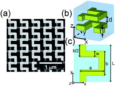
Fig. 1(a) presents the scanning electron microscopy (SEM) image of the bi-layer continuous gold (Au) omega-shaped metamaterial embedded in a silica substrate, and the whole coverage area of the sample is 50 μm × 50 μm. Schematics of the unit cell for perspective view and top view are presented in Fig. 1(b) and (c), respectively, with dimensions of the fabricated structure as a = 330 nm, b = 330 nm, w = 80 nm, t = 40 nm and L = 500 nm. It is worth mentioning that the distance between the top and bottom layer was d = 120 nm, which was the minimum distance for our fabrication. In order to demonstrate our experiment result, we have performed Finite Difference Time Domain (FDTD) method. And gold is used by a Drude-type model with plasma frequency ωp = 1.367 × 10¹⁶ rad s−1 and collision frequency γ = 4.0715 × 10¹³ rad s−1.35 Meanwhile, a silicon-oxide with εSiO2 = 2.1 is considered as dielectric environment. Herein, we used periodic boundary conditions in x- and y-directions to realize the continuous omega-shaped metamaterial, and the total transmittances were probed directly when the x- and y-polarized incident lights propagated along the forward (+z) and backward (−z) directions.For sample fabrication, the polymethyl methacrylate (PMMA) layer was first spin-coated onto the 500 μm-thick silica (SiO2) substrate. Similarly, a conductive polymer layer (Showa Denko, E-spacer 300Z) was also spin-coated to prevent the charging effect from the dielectric substrate. Then, the continuous omega-shaped pattern was exposed by an electron-beam lithography (EBL) system (ELIONIX ELS-7800, 80 kV, 50 pA). After exposing, the conductive polymer layer was first removed by DI water and then, the continuous omega-shaped pattern was developed and fixated by the MIBK![[thin space (1/6-em)]](https://www.rsc.org/images/entities/char_2009.gif) :
:![[thin space (1/6-em)]](https://www.rsc.org/images/entities/char_2009.gif) IPA 1
IPA 1![[thin space (1/6-em)]](https://www.rsc.org/images/entities/char_2009.gif) :
:![[thin space (1/6-em)]](https://www.rsc.org/images/entities/char_2009.gif) 3 solutions and IPA. Then, an adhesion layer with 3 nm-thick chrome and a structure layer with 40 nm-thick Au were deposited by electron-beam evaporation (KVT KVE-ENS4004). Hence, the first (bottom) continuous omega-shaped Au layer was transferred onto the substrate by a standard lift-off process. Next, on top of the first layer, a 120 nm-thick spin-on-glass polymer layer was spin-coated and baked. The lithography processes was repeated along with an ultra-accurate overlay process36 to obtain the second (upper) continuous omega-shaped Au layer. Finally, another SiO2 layer was deposited on top of the sample to encapsulate the continuous omega-shaped metamaterial in SiO2 environment.
3 solutions and IPA. Then, an adhesion layer with 3 nm-thick chrome and a structure layer with 40 nm-thick Au were deposited by electron-beam evaporation (KVT KVE-ENS4004). Hence, the first (bottom) continuous omega-shaped Au layer was transferred onto the substrate by a standard lift-off process. Next, on top of the first layer, a 120 nm-thick spin-on-glass polymer layer was spin-coated and baked. The lithography processes was repeated along with an ultra-accurate overlay process36 to obtain the second (upper) continuous omega-shaped Au layer. Finally, another SiO2 layer was deposited on top of the sample to encapsulate the continuous omega-shaped metamaterial in SiO2 environment.
Experimental results
It is known that the AT parameters (Δ) for linearly polarized light can be calculated by Δx = tfx − tbx and Δy = tfy − tby,37 where f and b indicate that the incident lights propagate along the forward and backward directions, respectively, and tx and ty indicate the total transmittances for the x- and y-polarized incident lights, respectively. Fig. 2 presents a homemade optical setup for measuring the spectra of total transmittances for both x- and y-polarized incident lights. In this experiment, we rotated the sample 180° along the x-direction for realizing the forward and backward illuminations. The white light (Ocean Optics, HL 2000) was first calibrated by the convex lens (L1). The convex lens from L2 to L4 ensured parallel illumination, and x- and y-polarized incident lights could be induced by the linear polarizer (P). In addition, diaphragms (D1, D2) and a filter (F) were used to control the faculae and light intensity. Then, the illuminated light was reflected to the objective 1 (O1: Olympus, 50×, N.A. 0.8) by the beam splitter (B) and focused on the sample. As a result, the light separated into two paths after interacting with the continuous omega-shaped metamaterial: one path light was focused on the charge-coupled device (CCD) to observe the sample, and the other path light passed through the sample and was collected by the objective 2 (O2: Olympus, 50×, N.A. 0.5) and measured by the spectroscopy analyzer (AQ6370C).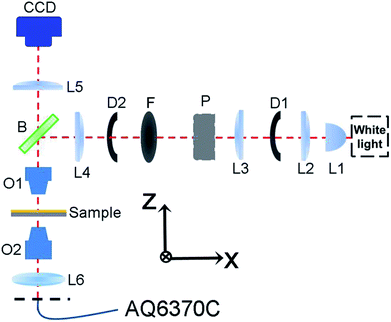 | ||
| Fig. 2 Schematic of the optical path designed for measuring the total transmittances for the x- and y-polarized incident light. | ||
Results and discussion
In order to clearly show the differences in total transmittances for linearly polarized light propagating along the two opposite directions, we have measured the total transmittances directly rather than the transmission coefficients in Jones matrix in our previous studies.35,38 Fig. 3(a) and (b) present the measured spectra of total transmittances recorded by the homemade optical setup shown in Fig. 2. For x-polarized incident light [Fig. 3(a)], the total transmittance for backward (−z) propagation (tbx) is about zero at around 1350 nm. In addition, the transmittance in forward (tfx) direction is 0.12 at around 1350 nm, which can be considered as an efficient transmittance compared with previous reports.29,39 Therefore, x-polarized incident light could pass through the continuous omega-shaped metamaterial along the forward direction, but it was prevented along the backward direction. As discussed in the former simulation study, it is known that the hybrid resonance and chiral arrangement of the bi-layer metamaterial result in a high transmittance for x-polarized incident light propagating along the forward direction.37 Moreover, the bi-layer metamaterial cannot induce a hybrid resonance for the x-polarized incident light propagating along the backward direction. Therefore, the backward transmittance is nearly zero. For the y-polarized incident light [Fig. 3(b)], only backward direction is allowed for the light to propagate through the sample rather than the forward direction. To confirm the experimental results, we performed simulations to numerically check the asymmetric total transmittances for the x- and y-polarized incident lights propagating along the forward and backward directions, as shown in Fig. 3(c) and (d). The simulated results show that the x-polarized incident light can only pass through the continuous omega-shaped metamaterial along the forward direction at a resonance wavelength of about 1400 nm. Inversely, the y-polarized incident light can only pass through the metamaterial along the backward direction at the same resonant wavelength. The overall tendency of the simulated spectra is in reasonable agreement with the measured result. Herein, the simulated total transmittances for x- and y-polarized incident lights propagating along the forward and backward directions were consistent (tfx = tby and tbx = tfy), which could be attributed to the spatial symmetry of the proposed bi-layer metamaterial. However, for the experiment, it is hard to keep an exactly x-/y-polarized incident light; as a result, the spatial symmetry is destroyed and the consistency disappeared. In addition, the fabrication errors in critical dimensions of the structures, uniformity coefficient of the middle coating film, noises of our homemade optical setup and other disturbances were responsible for the differences between experimental data in Fig. 3(a) and (b) and simulations in Fig. 3(c) and (d).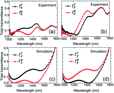 | ||
| Fig. 3 Measured (a) and (b) and simulated (c) and (d) total transmittances for x- and y-polarized incident light propagating along the forward and backward directions. | ||
Fig. 4(a) and (b) show the AT parameters for the experiment and simulation calculated by the equation Δx = tfx − tbx = −(tfy − tby) = −Δy. It is can be clearly found that the maximum values of AT peaks are about ±0.1 for the experiment, which agrees well with the simulated result of about ±0.18. The AT peaks appeared at around 1350 nm in the measured results, which suffered a slight blue shift compared with the simulations. As discussed in previous studies, the blue shift should come from the fabrication errors for parameter a in Fig. 1(c).37 Fig. 4(c) presents the AT efficiencies of the simulated (Sim.) and experimental (Exp.) results, which are shown by dotted and solid lines, respectively. From the simulated results, we can infer that for the continuous omega-shaped metamaterials, the AT parameters are sensitive to distance (d) between top and bottom layers, and the AT parameter reached up to 0.8 at d = 60 nm. However, the AT parameter is only 0.05 at d = 150 nm, which could be attributed to the resonance of Fabry–Perot-like cavity; also, the interactions between the incident wave and the bi-layer omega-shaped metamaterial are all weak.37,40 In addition, it was necessary to realize the AT effect experimentally,. Hence, in this study, we paid more attention on sample fabrications and AT measurements. However, it is still a challenge to decrease the distance to d = 60 nm. This is because if the thickness of the spacing layer is too low, the first layer cannot be uniformly covered and planarization cannot be achieved. Hence, the distance d could be decreased down to only 120 nm using spin-on-glass in this experimental study; as a result, the AT parameter could just reach nearly 0.1.37 Therefore, it is of great importance to further overcome the challenges in fabrications to realize better AT effects experimentally. Moreover, the multi-layered programmable metasurfaces have been proposed to improve the transmission at microwave and THz frequencies.41,42 Hence, increasing the layers of our omega-structure would be also considered to improve the AT efficiency at optical frequencies in future.
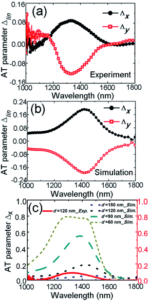 | ||
| Fig. 4 Measured (a) and simulated (b) asymmetric transmissions for x- and y-polarized lights; (c) asymmetric transmissions influenced by distance d between top and bottom layers. | ||
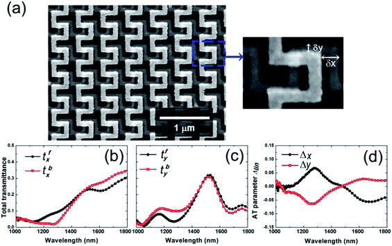
To study the influence of overlay fabrication imperfections, we experimentally examined the AT effect of the misaligned continuous omega-shaped metamaterial. Fig. 5(a) presents the SEM image of a misaligned omega-shaped sample with misalignments δx = 135 nm and δy = 50 nm. Then, total transmittances were measured by the same homemade optical setup. As presented in Fig. 5(b) and (c), the tendency of transmittance spectra is consistent with the spectra obtained from the original well-aligned sample in Fig. 2. Then, the corresponding AT parameters were calculated and shown in Fig. 5(d) with efficient AT values of about ±0.075.29 The working wavelength range and values of AT parameters were also approximated to the result in Fig. 4(a), where slight deviations could be attributed to uncontrollable factors in fabrications and measurements. Finally, we can conclude that the AT effect is robust towards the lateral misalignments between the top and bottom omega-shaped layers.
Summary
In summary, we have experimentally demonstrated the AT effect for linearly polarized light by continuous omega-shaped metamaterial, and the measured results were also confirmed by FDTD simulations. For fabrications, the alignment errors caused by the EBL machine were minimized to obtain well-aligned samples. In addition, we propose a simple homemade optical setup, which can measure the total transmittances of x-/y-polarized incident lights. Then, the forward and backward total transmittances can be realized by rotating the sample, so that the AT effect can be measured experimentally. Finally, we have also experimentally verified that our continuous omega-shaped metamaterial is robust against misalignment errors, which are unavoidable in fabrications, showing its high possibility in further practical applications.Conflicts of interest
There are no conflict to declare.Acknowledgements
This study was supported by the National Natural Science Foundation of China (No. 11774053, 11374049, 11511140278); National Research Foundation of Korea (NRF-2017R1E1A1A03070501, NRF-2015R1A5A1037668, CAMM-2014M3A6B3063708, NRF-2017R1E1A2A01076613); Ministry of Science and ICT of the Korean government (NRF-2016H1A2A1906519).Notes and references
- J. Shi, X. Liu, S. Yu, T. Lv, Z. Zhu, H. Feng Ma and T. Jun Cui, Appl. Phys. Lett., 2013, 102, 191905 CrossRef.
- S. Fang, K. Luan, H. F. Ma, W. Lv, Y. Li, Z. Zhu, C. Guan, J. Shi and T. J. Cui, J. Appl. Phys., 2017, 121, 033103 CrossRef.
- Y. R. Li and Y. C. Hung, Opt. Express, 2015, 23, 16772–16781 CrossRef CAS PubMed.
- C. Wu, H. Li, X. Yu, F. Li, H. Chen and C. T. Chan, Phys. Rev. Lett., 2011, 107, 177401 CrossRef PubMed.
- J. K. Gansel, M. Thiel, M. S. Rill, M. Decker, K. Bade, V. Saile, G. von Freymann, S. Linden and M. Wegener, Science, 2009, 325, 1513–1515 CrossRef CAS PubMed.
- J. Han, H. Li, Y. Fan, Z. Wei, C. Wu, Y. Cao, X. Yu, F. Li and Z. Wang, Appl. Phys. Lett., 2011, 98, 151908 CrossRef.
- W. Ma, Y. Wen and X. Yu, Opt. Express, 2013, 21, 30724–30730 CrossRef PubMed.
- T. J. Cui, M. Q. Qi, X. Wan, J. Zhao and Q. Cheng, Light: Sci. Appl., 2014, 3, e218 CrossRef.
- D. Yavorskiy, M. Stolarek, J. Lusakowski and R. Kotynski, Opt. Express, 2014, 22, 30547–30552 CrossRef PubMed.
- A. S. Schwanecke, V. A. Fedotov, V. V. Khardikov, S. L. Prosvirnin, Y. Chen and N. I. Zheludev, Nano Lett., 2008, 8, 2940–2943 CrossRef CAS PubMed.
- M. Kang, H. T. Wang and W. Zhu, Opt. Express, 2014, 22, 9301–9306 CrossRef CAS PubMed.
- Z. Li, M. Mutlu and E. Ozbay, J. Opt., 2013, 15, 023001 CrossRef.
- Z. Wang, F. Cheng, T. Winsor and Y. Liu, Nanotechnology, 2016, 27, 412001 CrossRef PubMed.
- Y. Zhao, M. A. Belkin and A. Alu, Nat. Commun., 2012, 3, 870 CrossRef CAS PubMed.
- R. Ji, S. W. Wang, X. Liu and W. Lu, Nanoscale, 2016, 8, 8189–8194 RSC.
- G. Kenanakis, A. Xomalis, A. Selimis, M. Vamvakaki, M. Farsari, M. Kafesaki, C. M. Soukoulis and E. N. Economou, ACS Photonics, 2015, 2, 287–294 CrossRef CAS.
- K. Chen, Y. Feng, L. Cui, J. Zhao, T. Jiang and B. Zhu, Sci. Rep., 2017, 7, 42802 CrossRef CAS PubMed.
- Z. Li, W. Liu, H. Cheng, S. Chen and J. Tian, Opt. Lett., 2016, 41, 3142–3145 CrossRef CAS PubMed.
- H. Jiang, W. Zhao and Y. Jiang, Opt. Express, 2017, 25, 19732–19769 CrossRef CAS PubMed.
- J. Zhao, Y. Fu, Z. Liu and J. Zhou, Opt. Express, 2017, 25, 23051–23059 CrossRef CAS PubMed.
- C. He, X.-L. Chen, M.-H. Lu, X.-F. Li, W.-W. Wan, X.-S. Qian, R.-C. Yin and Y.-F. Chen, Appl. Phys. Lett., 2010, 96, 111111 CrossRef.
- H. Zhu and C. Jiang, Opt. Lett., 2011, 36, 1308–1310 CrossRef PubMed.
- N. Bender, S. Factor, J. D. Bodyfelt, H. Ramezani, D. N. Christodoulides, F. M. Ellis and T. Kottos, Phys. Rev. Lett., 2013, 110, 234101 CrossRef CAS PubMed.
- S. Lepri and G. Casati, Phys. Rev. Lett., 2011, 106, 164101 CrossRef PubMed.
- Y. Ling, L. Huang, W. Hong, T. Liu, Y. Sun, J. Luan and G. Yuan, Opt. Express, 2017, 25, 13648–13658 CrossRef CAS PubMed.
- A. E. Serebryannikov, E. Ozbay and S. Nojima, Opt. Express, 2014, 22, 3075–3088 CrossRef PubMed.
- M. Stolarek, D. Yavorskiy, R. Kotynski, C. J. Zapata Rodriguez, J. Lusakowski and T. Szoplik, Opt. Lett., 2013, 38, 839–841 CrossRef PubMed.
- Z. Li, S. Chen, C. Tang, W. Liu, H. Cheng, Z. Liu, J. Li, P. Yu, B. Xie, Z. Liu, J. Li and J. Tian, Appl. Phys. Lett., 2014, 105, 201103 CrossRef.
- T. Aba, Y. Qu, T. Wang, Y. Chen, H. Li, Y. Wang, Y. Bai and Z. Zhang, Opt. Express, 2018, 26, 1199–1205 CrossRef PubMed.
- C. Pan, M. Ren, Q. Li, S. Fan and J. Xu, Appl. Phys. Lett., 2014, 104, 121112 CrossRef.
- D. F. Tang, C. Wang, W. K. Pan, M. H. Li and J. F. Dong, Opt. Express, 2017, 25, 11329–11339 CrossRef CAS PubMed.
- V. A. Fedotov, P. L. Mladyonov, S. L. Prosvirnin, A. V. Rogacheva, Y. Chen and N. I. Zheludev, Phys. Rev. Lett., 2006, 97, 167401 CrossRef CAS PubMed.
- L. Wu, Z. Yang, Y. Cheng, Z. Lu, P. Zhang, M. Zhao, R. Gong, X. Yuan, Y. Zheng and J. Duan, Opt. Express, 2013, 21, 5239–5246 CrossRef PubMed.
- C. Menzel, C. Helgert, C. Rockstuhl, E. B. Kley, A. Tunnermann, T. Pertsch and F. Lederer, Phys. Rev. Lett., 2010, 104, 253902 CrossRef CAS PubMed.
- M. Kim, K. Yao, G. Yoon, I. Kim, Y. Liu and J. Rho, Adv. Opt. Mater., 2017, 5, 1700600 CrossRef.
- G. Yoon, I. Kim, S. So, J. Mun, M. Kim and J. Rho, Sci. Rep., 2017, 7, 6668 CrossRef PubMed.
- Y. H. Wang, R. C. Jin, J. Li, J. Q. Li and Z. G. Dong, Opt. Express, 2018, 26, 3508–3517 CrossRef PubMed.
- C. Menzel, C. Rockstuhl and F. Lederer, Phys. Rev. A, 2010, 82, 053811 CrossRef.
- W.-Z. Xu, Y.-T. Shi, J. Ye, F.-F. Ren, I. V. Shadrivov, H. Lu, L. Liang, X. Hu, B. Jin, R. Zhang, Y. Zheng, H. H. Tan and C. Jagadish, Adv. Opt. Mater., 2017, 5, 1700108 CrossRef.
- Z. Li, S. Chen, W. Liu, H. Cheng, Z. Liu, J. Li, P. Yu, B. Xie and J. Tian, Plasmonics, 2015, 10, 1703 CrossRef CAS.
- S. Liu, A. Noor, L. L. Du, L. Zhang, Q. Xu, K. Luan, T. Q. Wang, Z. Tian, W. X. Tang, J. G. Han, W. L. Zhang, X. Y. Zhou, Q. Cheng and T. J. Cui, ACS Photonics, 2016, 3, 1968–1977 CrossRef CAS.
- L. Zhang, R. Y. Wu, G. D. Bai, H. T. Wu, Q. Ma, X. Q. Chen and T. J. Cui, Adv. Funct. Mater., 2018, 28, 1802205 CrossRef.
Footnote |
| † These authors contributed equally to the paper. |
| This journal is © The Royal Society of Chemistry 2018 |

