 Open Access Article
Facile fabrication of hierarchical film composed of Co(OH)2@Carbon nanotube core/sheath nanocables and its capacitive performance†
Hua Fang *a,
Gaoyun Chenb,
Lixia Wanga,
Ji Yana,
Linsen Zhanga,
Kezheng Gaoa,
Yongxia Zhanga and
Lizhen Wang*a
aSchool of Material and Chemical Engineering, Zhengzhou University of Light Industry, Zhengzhou 450001, PR China. E-mail: fh@zzuli.edu.cn; wlz@zzuli.edu.cn
bInstitute of Chemical Defense, Beijing, 102205, China
First published on 15th November 2018
Abstract
A hierarchical film composed of Co(OH)2@carbon nanotube (CNT) core/sheath nanocables (CCNF) was generated via a simple and rapid electrophoretic deposition method. It is found that the Co(OH)2 sheath was uniformly anchored on the surface of conductive CNT core. The Co(OH)2 sheath, with a thickness of ∼20 nm, was composed of numerous very tiny nanoparticles. Such a unique nanostructure endows the CCNF with a high surface area of 126 m2 g−1 and a hierarchical porosity, resulting in a large accessible surface area for redox activity. As expected, the CCNF exhibits high specific capacitance and excellent rate performance. Its specific capacitance reached 1215 F g−1 under a low current density of 1 A g−1 and was maintained at 832 F g−1 when the current density was increased 20 times to 20 A g−1. A high capacitance retention of 99.3% was achieved after 10![[thin space (1/6-em)]](https://www.rsc.org/images/entities/char_2009.gif) 000 cycles at 1 A g−1. Such intriguing capacitive behavior is attributed to the synergistic effect of the CNT core and the Co(OH)2 sheath.
000 cycles at 1 A g−1. Such intriguing capacitive behavior is attributed to the synergistic effect of the CNT core and the Co(OH)2 sheath.
Introduction
Supercapacitors (SCs), also known as electrochemical capacitors, have attracted much attention as promising candidates for next-generation power energy storage devices due to their high power density, high cycle stability and environmental benignity.1 Based on the energy storage mechanism, SCs can be divided into electric double layer capacitors (EDLCs, store energy via highly reversible ion adsorption/desorption) and pseudocapacitors (store energy based on fast surface redox reactions).2 Compared to EDLCs, pseudocapacitors could provide higher energy densities.3 As is known, the materials for pseudocapacitors, such as transition metal compounds and conducting polymers, have been intensively investigated in recent years. Among these, Co(OH)2 can be regarded as an ideal candidate electrode material owing to its high theoretical capacitance of 3458 F g−1, low cost, high redox activity and outstanding reversibility.4–8 However, Co(OH)2 often suffers from high electrical resistance due to its chemical nature.9In order to improve the capacitive performances of the Co(OH)2 based electrodes, various carbon materials, such as carbon nanotubes (CNTs)1,10–15 and graphene,16–21 are introduced to form carbon/Co(OH)2 hybrids. Due to their high surface area and excellent conductivity, the carbon materials can act as structure matrix to enhance conductivity and to enlarge specific surface area.1 Among the various carbon materials, CNTs are an important one-dimensional (1D) carbon nanomaterial with a huge aspect ratio and a unique combination of mechanical, electrical, and thermal properties.11 Thus, several CNTs/Co(OH)2 hybrids have been reported with improved performances. For example, Mondal et al. synthesized CNT wrapped Co(OH)2 flakes by using a hydrothermal approach, which showed high specific capacitance of 603 F g−1 at 1 mV s−1 scan rate.11 Li et al. fabricated a CNT/Ni–Co hydroxide nanoflake core/shell structure by chemical bath deposition method, which exhibited a high specific capacitance of 1151 F g−1 at 1 A g−1 and an excellent high rate capability.13 The above mentioned progresses point the way forward in the search for further improvement of capacitive performances. However, most of the reported CNTs/Co(OH)2 hybrids were prepared by hydrothermal, precipitation or other complicated methods, which hinders their application.
Herein, a hierarchical film composed of Co(OH)2@CNT core/sheath nanocables(CCNF) was successfully fabricated by an facile electrophoretic deposition (EPD) approach. The obtained CCNF showed high surface area and hierarchical three-dimensional (3D) interconnected porosity. As designed, excellent electrochemical properties were achieved, presenting a low-cost and high performance material for pseudocapacitor.
Experimental
Fabrication of CCNF
All the chemicals were of analytical grade and were not purified further before use. CNTs were purchased from Chengdu Organic Chemicals Co. Ltd. (Chengdu, China), with length and outer diameter of 0.5–2 μm and ∼50 nm, respectively. Before use, CNTs were subjected to an oxidation treatment by refluxing in concentrated HNO3 for 6 h.For preparing CCNF, 25 mg of pretreated CNTs were ultrasonically dispersed in 200 ml of 2 M cobalt nitrate ethanol solution. A nickle foil (3 cm × 4 cm) and a platinum foil (3 cm × 4 cm) were put into the hybrid suspension as the cathode and anode, respectively. The two electrodes were kept parallel and 1 cm apart. The deposition voltage was set as 50 V and the deposition time was 300 s. After deposition, the obtained film was washed with absolute ethanol and dried at 120 °C for 2 h in an air dry oven. The experimental setup in the EPD process and the obtained CCNF electrode are shown in Fig. S1.†
Materials characterization
The obtained CCNF was characterized by powder X-ray diffraction (XRD, Bruker Axs DS Advance) with Cu Kα radiation. The morphologies and structures were observed by field emission scanning electron microscopy (SEM, JSM-7001F), transmission electron microscope (TEM, JSM-700) and high resolution transmission electron microscopy (HR-TEM). The mass content of Co(OH)2 in CCNF was checked by thermogravimetric (TG) analysis (in air, 25 mL min−1, 25–900 °C, 10 °C min−1) by using a simultaneous thermal analyzer (Diamond Perkin Elmer S II). The mass content of Co(OH)2 was also checked by energy dispersive spectrometry (EDS, JSM-6490LV). Nitrogen adsorption/desorption test was performed at 77 K on a specific surface and porosity analyzer (BELSORP-Mini II). The specific surface area was estimated by using the Brunauer–Emmett–Teller (BET) method. The pore size distribution was achieved by Barrett–Joyner–Halenda (BJH) method.Electrochemical measurements
The electrochemical measurements were performed by using three-electrode system in 6 M KOH aqueous solution at room temperature, which is shown in Fig. S2.† The as-prepared CCNF, a platinum foil and a saturated calomel electrode (SCE) were used as the working, counter and reference electrodes respectively. Cyclic voltammetry (CV) test were performed on a CHI 604e electrochemical workstation. Galvanostatic charge/discharge (GCD) tests were performed at different current densities from 1 to 20 A g−1 on a Neware 2001 battery test system (Neware Instruments). The specific capacitances were calculated according to the formula of Cm = It/mΔU, where I is the constant discharge current (s), t is the discharging time (s), m is the mass of the active materials (g), ΔU is the potential change in discharge (V).22 The mass ratio of Co(OH)2 in CCNF was 61.7 wt% according to TG test.Results and discussion
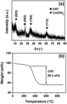
The fabrication strategy of CCNF is displayed in Scheme 1. Firstly, an oxidation treatment of CNTs was performed to introduce functional groups (e.g., hydroxyl, carbonyl, and carboxyl). These surface functional groups are known to facilitate the dispersion of CNTs and serve as nucleation centers for the deposition of Co(OH)2. Secondly, a uniform coating of Co(OH)2 was produced on the skeleton of CNTs in a facile EPD process, resulting in a unique core/sheath nanocable microstructure. A micro-cathode induced coating mechanism was proposed to explain the possible formation mechanism of the one-step construction of core/sheath microstructure in our previous report.23 The unique core/sheath heterostructure is evidenced by the following characterization results, in which Co(OH)2 sheath is uniformly coated on the sidewall of CNTs.XRD measurement was performed to characterize the phases of the CCNF composite. As shown in Fig. 1a, the characteristic graphitic peak at 25.6° is clearly evident, indicating the presence of CNTs. The diffraction peaks at 11.5°, 34.5° and 61.2° are consistent with the (003), (102) and (110) plane of the α-Co(OH)2, which is in well agreement with the standard pattern (JCPDS 46-0605).18 The XRD peaks are broad and weak, indicating the poor crystallinity and polycrystalline nature of the Co(OH)2.
Fig. 1b shows the TG curves of the CCNF from 25 to 900 °C in air. The first weight loss stage below 150 °C is due to the removal of adsorbed water and intercalated water. The second weight loss stage in the temperature range of 150–300 °C is attributed to the dehydroxylation of the Co(OH)2 sheath. Thereafter, the third weight loss between 300 and 500 °C should be corresponding to the complete oxygenolysis of CNT core, which is consistent with the previous reported results.11,14 As a result, the weight ratio of Co(OH)2 sheath in CCNF is ∼61.7%. This TG result is consistent with the EDS measurement. As shown in Fig. S3,† the EDS result showed that the weight ratio of Co(OH)2 sheath in CCNF is ∼67.7%.
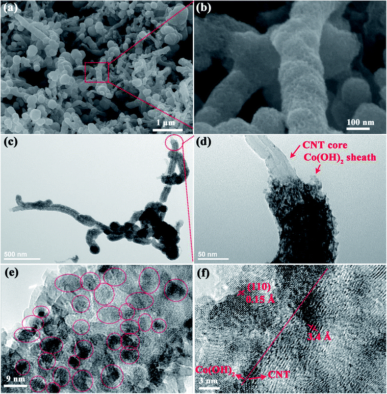
SEM and TEM were performed to investigate the morphology and microstructure of the CCNF samples. Fig. 2a reveals that one-dimensional (1D) fibrous CCNF (with a diameter of ∼100 nm) are intertwined with each other into a three-dimensional (3D) network morphology, with an open and porous structure. Hardly any bare CNT left out, indicating that the Co(OH)2 sheath was homogeneously distributed on the sidewall of CNT core. Fig. 2b depicts that the CCNF shows a nanoporous sidewall, proving that the Co(OH)2 sheath is composed of very thin nanoparticles.
The TEM images of the CCNF were presented to demonstrate their microstructure more clearly. As seen in Fig. 2c, entire Co(OH)2 sheath is anchored on the surface of CNT, indicating the robust adhesion between Co(OH)2 and CNT substrate. The core/sheath nanocable microstructure can be further demonstrated by Fig. 2d, where a bare CNT end can be clearly found. The thickness of the Co(OH)2 sheath is ∼20 nm. As shown by Fig. 2e, the Co(OH)2 sheath is composed of number of very tiny Co(OH)2 nanoparticles, which are uniformly anchored on CNT matrix. The particle size ranges from ∼3 to ∼6 nm in diameters.
As shown in Fig. 2f, the lattice fringes with d-spacings of 1.5 Å and 3.4 Å can be well indexed to (110) plane of α-Co(OH)2 (JCPDS card no. 46-0605) and (002) plane of CNT, respectively. The grain boundary can be clearly seen in Fig. 2f, further proving that the Co(OH)2 sheath is composed of very tiny nanoparticles. The CNTs, which are interconnected with each other into a highly conductive matrix, are utilized to disperse Co(OH)2 nanoparticles uniformly. The CNT matrix can offer a fast pathway for electron transport, favouring high power performance. The very tiny Co(OH)2 nanoparticles can provide high surface area for fast electrochemical redox reactions.
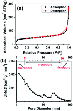
As shown in Fig. 3a, the N2 adsorption–desorption isotherm of the CCNF showed a combined I/IV type adsorption–desorption isotherms with a H3 hysteresis loop, indicating the presence of slit-like pores.24 The CCNF possessed a high specific surface area of 126 m2 g−1, an average pore size of 9.3 nm and a total pore volume of 0.29 m3 g−1. As shown in Fig. 3b, the CCNF showed a wide pore size distribution ranging from 1 nm to 100 nm, which indicates that there are micropores (<2 nm), mesopore (2–50 nm) and macropore (>50 nm). Combined with the SEM images shown in Fig. 2a, conclusion can be drawn that the CCNF possesses a 3D hierarchically interconnected network structure. Such hierarchical structure is beneficial for the efficient ion transport during the charge/discharge processes, resulting in a large accessible surface area for redox activity.4 Specifically speaking, the macropores could serve as ion-buffering reservoirs to provide short diffusion distance for the diffusion of electrolyte ions, while the mesopores can facilitate ion transport to the interior of the bulk materials, which will in turn improve the availability of the micropores. The micropores can provide high specific surface, thus providing high pseudocapacitance and good power performance.24 In addition, such hierarchical nanostructure could prevent the electrode from severe structural damage and capacity loss during long-time charge/discharge test.
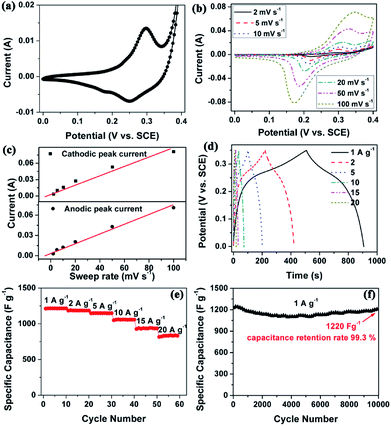
Electrochemical measurements were conducted to evaluate the electrochemical properties of the CCNF. Fig. 4a shows the CV curve of CCNF electrodes in the voltage range of 0–0.4 V (vs. SCE) at a scan rate of 10 mV s−1. A pair of redox peaks can be observed in the voltammogram, which indicates that the capacitance mainly comes from faradaic redox reaction of Co(OH)2. The redox reactions can be expressed as follows:25
| Co(OH)2 + OH− ↔ CoOOH + H2O + e− | (1) |
| CoOOH + OH− ↔ CoO2 + H2O + e− | (2) |
It is known that both rechargeable batteries and pseudocapacitors store charges via electrochemical redox reactions of the electrode-active materials. The former is limited by cation diffusion within the crystalline framework of active material, while the latter is not controlled by the diffusion process.26 CV investigation is an efficient tool to clarify this kinetic difference.26 Due to that typical capacitive behaviour or pseudocapacitive behaviour is not diffusion-controlled, the current (i) should vary linearly with the sweep rate (v) according to the equation of i = CdAv, where Cd represents the capacitance and A is the surface area of the active materials.26,27 Recently, an oriented multiwalled organic–Co(OH)2 nanotubes were reported and proved to be pseudocapacitive by CV tests.4
Thus, CV tests were performed at different scan rates to investigate the electrochemical kinetic properties. As shown in Fig. 4b and c, the anodic/cathodic peak currents were linear to sweep rates, indicating that the current response is predominately capacitive in nature. As mentioned above, the hierarchical porous nanostructure facilitates fast ion diffusion and the high surface area provides higher accessible surface area for fast surface faradic reactions. Therefore, the CCNF electrode should not be controlled by the diffusion process, which can explain its pseudocapacitive behavior.
Fig. 4d shows the GCD curves of the CCNF at different current densities ranging from 1 to 20 A g−1. The nonlinear lines also confirm the pseudocapacitance behaviour of the CCNF electrode. The specific capacitance is calculated from the GCD curves, which is depicted in Fig. 4e. The CCNF shows high specific capacitances of 1215 and 832 F g−1 at constant current densities of 1 and 20 A g−1, respectively. The capacitance retention rate reaches as high as 68.5% when the current density increased by 20 times from 1 to 20 A g−1, proving the superior rate capability of the CCNF.
The cycle stability is critical for the practical application in supercapacitors. As shown in Fig. 4f, the CCNF electrode show a capacitance retention rate of 99.3% after 10![[thin space (1/6-em)]](https://www.rsc.org/images/entities/char_2009.gif) 000 GCD cycles, proving its superior electrochemical stability and reversibility.
000 GCD cycles, proving its superior electrochemical stability and reversibility.
The excellent capacitive performance of CCNF is also compared with other previously reported similar materials. As shown by Table 1, the CCNF shows comparatively high specific capacitance and outstanding long cycle life stability, proving to be a promising electrode material for high performance supercapacitors.
| Sample | Specific capacitance/current density | Capacitance retention rate/current density/cycle number | Reference |
|---|---|---|---|
| Layered α-Co(OH)2 nanocones | 1055 F g−1/1 Ag−1 | 95%/5 Ag−1/2000 | 5 |
| Heterogeneous Co3O4-nanocube/Co(OH)2-nanosheet hybrid | 1164 F g−1/1.2 Ag−1 | 97.4%/1.2 Ag−1/6000 | 6 |
| β-Co(OH)2 nanosheets/RGO hybrid | 3355 F g−1/1 Ag−1 | No decay/10 Ag−1/4000 | 9 |
| CNT wrapped Co(OH)2 flakes | 603 F g−1/1 mV s−1 | 96%/1.5 Ag−1/1000 | 11 |
| Ni–Co hydroxides/CNTs composites | 1151 F g−1/1 Ag−1 | 77%/1 Ag−1/10![[thin space (1/6-em)]](https://www.rsc.org/images/entities/char_2009.gif) 000 000 |
13 |
| Co(OH)2/graphene/Ni foam nano-electrodes | 694 F g−1/2 Ag−1 | 91.9%/40 Ag−1/3000 | 18 |
| Delaminated α-Co(OH)2@graphene | 567 F g−1/1 Ag−1 | 82%/1 Ag−1/2000 | 19 |
| Flower-like Co(OH)2/N-doped graphene composite | 2276 F g−1/1 Ag−1 | 93.5%/10 Ag−1/2000 | 21 |
| Co(OH)xCO3 with hierarchical flowery architecture | 550 F g−1/2 Ag−1 | 99.5%/5 Ag−1/1500 | 22 |
| Hierarchical film composed of Co(OH)2@CNT core/sheath nanocable | 1215 F g−1/1 Ag−1 | 99.3%/1 Ag−1/10![[thin space (1/6-em)]](https://www.rsc.org/images/entities/char_2009.gif) 000 000 |
This work |
Conclusions
In summary, we have fabricated a hierarchical film composed of Co(OH)2@CNT core/sheath nanocables (CCNF) by a facile EPD approach. Electrochemical analysis shows that a high specific capacitance of 1215 F g−1 is achieved at current density of 1 A g−1. Besides, the capacitance retention rate reaches 99.3% after 10![[thin space (1/6-em)]](https://www.rsc.org/images/entities/char_2009.gif) 000 continuous GCD cycles at 1 A g−1, demonstrating their good electrochemical stability. Such intriguing capacitive behaviour is attributed to the synergistic effect of the CNTs core and the Co(OH)2 sheath. In addition, the 3D hierarchical core/sheath microstructure is expected to provide fast ion transportation pathways, huge specific surface area and good electronic conductivity. Hereby, the synthesis route reported here is simple, scalable and cost-effective. It is expected that it could be extended to the synthesis of other metal hydroxides with hierarchically porous core/shell structure for fast energy storage.
000 continuous GCD cycles at 1 A g−1, demonstrating their good electrochemical stability. Such intriguing capacitive behaviour is attributed to the synergistic effect of the CNTs core and the Co(OH)2 sheath. In addition, the 3D hierarchical core/sheath microstructure is expected to provide fast ion transportation pathways, huge specific surface area and good electronic conductivity. Hereby, the synthesis route reported here is simple, scalable and cost-effective. It is expected that it could be extended to the synthesis of other metal hydroxides with hierarchically porous core/shell structure for fast energy storage.
Conflicts of interest
There are no conflicts to declare.Acknowledgements
This work was supported by the National Natural Science Foundation of China (grant numbers U1504204, 21506198 and 21471135).Notes and references
- C. L. Wang, H. L. Qu, T. Peng, K. Y. Mei, Y. Qiu, Y. Lu, Y. S. Luo and B. H. Yu, Electrochim. Acta, 2016, 191, 133 CrossRef CAS.
- Z. Y. Yu, Z. X. Cheng, X. L. Wang, S. X. Dou and X. Y. Kong, J. Mater. Chem. A, 2017, 5, 7968 RSC.
- N. Yulian, L. Ruiyi, L. Zaijun, F. Yinjun and L. Junkang, Electrochim. Acta, 2013, 94, 360 CrossRef.
- G. C. Lau, N. A. Sather, H. Sai, E. M. Waring, E. Deiss-Yehiely, L. Barreda, E. A. Beeman, L. C. Palmer and S. I. Stupp, Adv. Funct. Mater., 2018, 28, 1702320 CrossRef.
- L. Wang, Z. H. Dong, Z. G. Wang, F. X. Zhang and J. Jin, Adv. Funct. Mater., 2013, 23, 2758 CrossRef CAS.
- H. Pang, X. R. Li, Q. X. Zhao, H. G. Xue, W. Y. Lai, Z. Hu and W. Huang, Nano Energy, 2017, 35, 138 CrossRef CAS.
- T. Deng, W. Zhang, O. Arcelus, J. G. Kim, J. Carrasco, S. J. Yoo, W. T. Zheng, J. F. Wang, H. W. Tian, H. B. Zhang, X. Q. Cui and T. Rojo, Nat. Commun., 2017, 8, 15194 CrossRef CAS PubMed.
- Y. Z. Chen, W. K. Pang, H. H. Bai, T. F. Zhou, Y. N. Liu, S. Li and Z. P. Guo, Nano Lett., 2017, 17, 429 CrossRef CAS PubMed.
- L. Wang, C. Lin, F. Zhang and J. Jin, ACS Nano, 2014, 8, 3724 CrossRef CAS PubMed.
- H. Y. Chen, F. Cai, Y. R. Kang, S. Zeng, M. H. Chen and Q. W. Li, ACS Appl. Mater. Interfaces, 2014, 6, 19630 CrossRef CAS PubMed.
- C. Mondal, D. Ghosh, M. Ganguly, A. K. Sasmal, A. Roy and T. Pal, Appl. Surf. Sci., 2015, 359, 500 CrossRef CAS.
- H. J. Ahn, W. B. Kim and T. Y. Seong, Electrochem. Commun., 2008, 10, 1284 CrossRef CAS.
- M. Li, K. Y. Ma, J. P. Cheng, D. H. Lv and X. B. Zhang, J. Power Sources, 2015, 286, 438 CrossRef CAS.
- Y. Zhang, J. Wu, T. X. Zheng, Y. X. Zhang and H. Liu, Mater. Technol., 2016, 31, 521 CrossRef CAS.
- Q. Cheng, J. Tang, N. Shinya and L. C. Qin, Sci. Technol. Adv. Mater., 2014, 15, 014206 CrossRef PubMed.
- S. X. Yuan, C. X. Lu, Y. Li and X. M. Wang, ChemElectroChem, 2017, 4, 2826 CrossRef CAS.
- B. Rezaei, A. R. T. Jahromi and A. A. Ensafi, Int. J. Hydrogen Energy, 2017, 42, 16538 CrossRef CAS.
- C. M. Zhao, X. Wang, S. M. Wang, Y. Y. Wang, Y. X. Zhao and W. T. Zheng, Int. J. Hydrogen Energy, 2012, 37, 11846 CrossRef CAS.
- J. P. Cheng, L. Liu, K. Y. Ma, X. Wang, Q. Q. Li, J. S. Wu and F. Liu, J. Colloid Interface Sci., 2017, 486, 344 CrossRef CAS PubMed.
- E. M. Jin, H. J. Lee, H. B. Jun and S. M. Jeong, Korean J. Chem. Eng., 2017, 34, 885 CrossRef CAS.
- L. Bao, T. Li, S. Chen, Y. K. He, C. Peng, L. Li, Q. Xu, E. C. Ou and W. J. Xu, Mater. Lett., 2016, 185, 72 CrossRef CAS.
- X. J. Li, W. Xing, J. Zhou, G. Q. Wang, S. P. Zhuo, Z. F. Yan, Q. Z. Xue and S. Z. Qiao, Chem.–Eur. J., 2014, 20, 13314 CrossRef CAS PubMed.
- H. Fang, S. Zhang, W. Liu, Z. Du, X. Wu and Y. Xing, Electrochim. Acta, 2013, 108, 651 CrossRef CAS.
- Q. Wang, J. Yan, Y. Wang, T. Wei, M. Zhang, X. Jing and Z. Fan, Carbon, 2014, 67, 119 CrossRef CAS.
- J. Pu, Y. Tong, S. Wang, E. Sheng and Z. Wang, J. Power Sources, 2014, 250, 250 CrossRef CAS.
- Y. Wang, Y. Song and Y. Xia, Chem. Soc. Rev., 2016, 45, 5925 RSC.
- T. Brezesinski, J. Wang, S. H. Tolbert and B. Dunn, Nat. Mater., 2010, 9, 146 CrossRef CAS PubMed.
Footnote |
| † Electronic supplementary information (ESI) available. See DOI: 10.1039/c8ra07031h |
| This journal is © The Royal Society of Chemistry 2018 |


