
 Open Access Article
 This Open Access Article is licensed under a Creative Commons Attribution-Non Commercial 3.0 Unported Licence
C-doping into h-BN at low annealing temperature by alkaline earth metal borate for photoredox activity†
Myonghak Ri‡
ab,
Kwanghak Choe‡ab,
Kumchol Kim‡ab,
Yan Gao *a and
Zhiyong Tang*a
*a and
Zhiyong Tang*a
aCAS Key Laboratory of Nanosystem and Hierarchical Fabrication, CAS Center for Excellence in Nanoscience, National Center for Nanoscience and Technology, No. 11, Beiyitiao, Zhongguancun, Beijing 100190, P. R. China. E-mail: zytang@nanoctr.cn; gaoyan@nanoctr.cn
bUniversity of Chinese Academy of Sciences, Beijing 100049, China
First published on 18th December 2018
Abstract
BCN (boron carbon nitride) nanosheets are promising photocatalyst materials for solar fuel production by visible light-driven water splitting and CO2 reduction due to their tunable band gap and unique properties. C-doping into h-BN by thermal annealing makes possible the preparation of BCN nanosheets with photocatalytic activity under visible light irradiation, but it generally requires a very high temperature (>1250 °C) from the thermodynamic viewpoint. Here, we report a new method to prepare BCN nanosheets with visible light-photocatalytic activity at lower annealing temperature (1000 °C) than equilibrium by adding alkaline earth metal compounds. BCN nanosheets formed in borate melt show a clear layered structure, tunable bandgap and photocatalytic activity for water splitting and CO2 reduction under visible light illumination. This provides a direction for doping other elements into h-BN at low annealing temperature by alkaline earth metal borates.
Introduction
The development of photocatalysts for water splitting and CO2 reduction is of great significance for solar fuel production and the solution of global warming problems by using abundant and clean solar energy.1,2A number of photocatalyst materials such as inorganic semiconductor,3,4 metal–organic crystalline (MOF),5 conjugated microporous polymer (CMP),6 and carbon-based nanomaterials7 and their composites8 have been reported for photocatalysis. Among these materials, metal-free graphitic conjugated materials composed of lightweight and abundant elements attract much attention due to their non-toxicity and stability in the catalytic process. The materials based on g-C3N4 and graphene have been extensively studied and have good capability in the photocatalytic process. For example, Ru complex/C3N4 hybrid material could efficiently catalyze the conversion of CO2 to HCOOH in the DMA/TEA reaction systems under visible-light illumination, which gave a high turnover number (>1000) and apparent quantum yield (5.7% at 400 nm).7
Moreover, the Z-scheme photocatalytic systems constructed by applying graphene to connect CuGaS2 and CoOx/BiVO4 composites not only could split water into H2 and O2 but also was active in CO2 reduction using water as the sole electron donor under visible light.8
Recently, BCN nanosheets have been given attention of many researchers due to its higher efficient H2 production than g-C3N4 and CO2 reduction (moderate photocatalytic ability) under visible light irradiation9 and its tuneable band gap.10–12
Graphene13 is a single-layer 2D nanosheet with hexagonal packed lattice structure and a semimetal with a bandgap of 0 eV, while h-BN14 is a layer-structured insulator with a wide bandgap of ∼6.4 eV.
Graphite and h-BN can be doped each other because of similar crystal structure and physical properties.15–24 Therefore, this reciprocal doping can be used to tune their optical and electric properties19,25,26 and band gap between graphite and h-BN depending mainly on composition.27,28
Due to its unique properties of parent compounds and synergistic effects29,30 of the doped elements, BCN nanosheets can be used as free-metal electrode materials31 for ORR, supercapacitor,32 photocatalyst9 for solar fuel, microwave shielding materials33 and catalyst.34 BCN nanosheets can be prepared by several methods such as thermal annealing,1 MOCVD,35,36 hydrothermal reaction32 and electrochemical preparation.32 Specially, thermal annealing is most widely used for BCN nanosheets due to some advantages such as availability of precursor material, simple synthesis and gram scale yield, and no requirement of expensive instrument.
However, this doping by thermal annealing requires generally high temperature from thermodynamic viewpoint.36 Uddin et al. have reported that in the process of BCN nanosheets synthesis by MOCVD, (BN)1−X(C2)X nanosheets with 0.032 < x < 0.95 on the h-BN substrate are most likely phase separated at temperature of 1300 °C due to the bond energy difference.37 And Huang et al. have reported the preparation of C-doped BN nanosheets for photoredox catalysis at high annealing temperature (1250 °C).9 Also, Çamurlu and Antonietti have reported the calcium borate melt promotes the formation of h-BN in B2O3–C system by dissolving N2.38,39
Here we report a facile synthesis method for C-doping into h-BN at low annealing temperature (1000 °C) by adding alkaline earth metal compounds and the photocatalytic activity of the prepared BCN nanosheets for water splitting and CO2 reduction under visible light irradiation.
Experimental
Chemicals
Boric acid (H3BO3, 99.97%), urea (NH2CONH2, 99.3+%), D-(+)-glucose (99%), calcium nitrate tetrahydrate (Ca(NO3)2·4H2O, 99%), magnesium nitrate hexahydrate (Mg(NO3)2·6H2O, 98.0–102.0%), strontium nitrate (Sr(NO3)2, 99.0+%), barium nitrate (Ba(NO3)2, 99.95%), silver nitrate (AgNO3, 99.9+%), nickel(II) nitrate hexahydrate (Ni(NO3)2·6H2O, 98%), 2,2′-bipyridine (99+%), lanthanum(III) oxide (La2O3, 99.99%) were purchased from Alfa Aesar. Cobalt nitrate hexahydrate (Co(NO3)2·6H2O, 99%) was purchased from Aladdin and cobalt chloride (CoCl2·6H2O, 99.99%) from MACKLIN.Other analytical grade solvents including ethanol, acetonitrile and chemicals such as potassium hydroxide, ammonia solution, hydrochloric acid and triethanolamine were supplied by Sinopharm.
Preparation of BCN nanosheets
Boric acid (1 g), urea (4 g), alkaline earth metal nitrate (1.3 mmol) and a certain amount of glucose are mixed in aqueous solution and then dried at 70 °C under stirring in oil bath. The dried samples were again dried at 200 °C for 1 hour and then grinded fully in agate mortar. Then the samples are put in horizontal tubular furnace and, before heating up the system was degassed by vacuum pump and backfilled with pure N2 gas. Samples were then annealed at 1000 °C for 4 hours under N2 flow of 100 ml min−1. After annealing, samples are cooled to room temperature and then treated with 10% HNO3 solution at 80 °C and washed in water and ethanol. Samples were exfoliated by ultrasonic and then dried at 100 °C. The process is illustrated schematically in Scheme 1.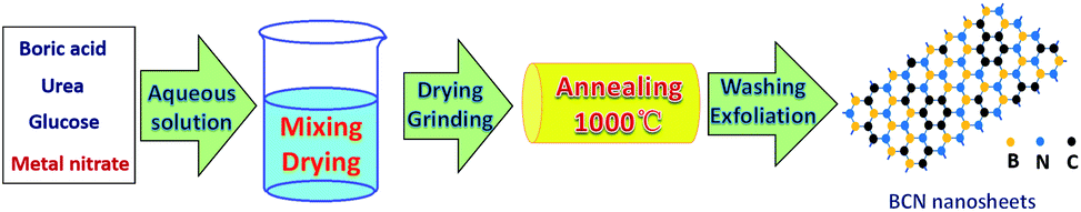 | ||
| Scheme 1 Schematic diagram for the preparation of BCN nanosheets at low annealing temperature by adding alkaline earth metal compound. | ||
The resulting final samples were denoted as xGlu-Me, where x (10, 20, 30, 40) is the percentage content of glucose by weight to boron oxide and Me (Mg, Ca, Sr and Ba) is alkaline earth metal. When either metal nitrate or glucose was omitted, the synthesized sample was named xGlu-Nm and h-BN, respectively.
The detailed preparation method of BCN nanosheets is described in ESI Method 1.†
Characterization
Powder X-ray diffraction (XRD) patterns were recorded on a PANalytical X'Pert-pro MPD X-ray power diffractometer with Cu-Kα radiation (λ = 1.54056 Å) operating at 50 kV and 300 mA. Fourier transform infrared (FT-IR) spectra were recorded on a Spectrum One in the spectral range of 400–4000 cm−1 using the KBr disk method. Scanning electron microscopy (SEM) measurement was performed on a Hitachi S4800 scanning electron microscope at 6.0 kV. Transmission electron microscopy (TEM) and high-resolution TEM (HRTEM) imaging was carried out using FEI Tecnai G2 F20 S-TWIN at 200 kV. High angle annular dark field scanning transmission electron microscopy (HAADF-STEM) imaging and energy-dispersive X-ray spectroscopy (EDS) elemental mapping were carried out on JEM-ARM 200F at 200 kV. X-ray photoelectron spectroscopy (XPS) spectra were performed by an ESCALAB 20 Xi XPS system, where the analysis chamber was 1.5 × 10⁻⁹ mbar and the size of X-ray spot was 500 μm. Raman spectroscopic measurements were performed on a Renishaw in Via plus with a 514 nm Nd:YAG excitation source at room temperature. The UV/Vis picture was recorded on a U-3900H Spectrophotometer, Hitachi. Here BaSO4 was used as a reflectance standard in the ultraviolet-visible diffuse reflectance experiment. The specific surface area were measured S2 using a BET (Brunauer–Emmett–Teller) instrument (ASAP 2420-4, Micromeritics). AFM measurements were implemented by using a Veeco Dimension 3100 SPM system. Photoelectrochemical analysis was conducted with an Electrochemical Workstation CHI660E in a three electrode cell, using an Ag/AgCl electrode (3 M KCl) as the reference electrode and a Pt plate as the counter electrode. The working electrode was prepared by spreading with catalyst slurry (5 mg ml−1 in DMF) on indium–tin oxide. After air drying, the working electrode was put into a 0.2 M Na2SO4 aqueous solution (pH = 6.8). The methods for the preparation of Ni–Co LDHs/30Glu-Ca for water oxidation, photocatalytic redox of water and reduction of CO2 are described minutely in ESI Method 2–4.†Result and discussion
Characterization of xGlu-Me samples
As shown in ESI Table 1 and Fig. 16,† the samples with glucose of more than 20 wt% to boric acid and without the addition of metal nitrate show black colour, which can be considered as the phase separation of carbon. But the samples with alkaline earth metal nitrate don't show black colour even at the addition of 40 wt% glucose. It is obvious that the addition of the alkaline earth metal compounds prevent the phase separation during the annealing. The difference in colours of samples with same glucose content according to the type of alkaline earth metal seems to be caused by the size and distribution of doped carbon domains in BCN materials.Fig. 1a and ESI Fig. 1† show the XRD patterns of the samples (xGlu-Ca) with different amounts of glucose and the samples (30Glu-Me) with alkaline earth metal nitrates.
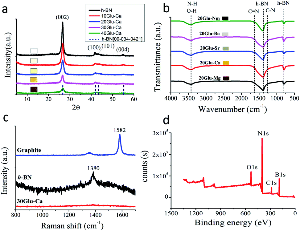 | ||
| Fig. 1 Structure of the prepared samples. (a) XRD patterns of xGlu-Ca (x = 0, 10, 20, 30, 40) samples. (b) FT-IR spectra of 20Glu-Me (Me = Mg, Ca, Sr, Ba, no metal) samples. (c) Raman shift of 30Glu-Ca sample. (d) XPS survey of 30Glu-Ca sample. | ||
All samples showed the XRD patterns that resembles the pattern of h-BN (JCPDS card no. 00-034-0421) and all the observed peaks were matching those with the h-BN structure. The most intense and sharp peak at ∼26° can be assigned to the (002) plane corresponding to regular van der Waals stacking of hexagonal BN layers. Additionally, the peaks observed at ∼42°, ∼43° and ∼55°correspond to (100), (101) and (004), crystallographic planes, respectively. The higher the content of glucose is, the lower the peak intensity of h-BN is.40 Also, with increasing the C-doping content, the peaks were broadened and shifted slightly to lower angles, which indicates the doping of carbon in the h-BN lattice. These results reveal that all samples have a layered structure similar to h-BN and the inherent property of h-BN becomes weakened as the C-doping content increase.
Fourier transform infrared (FT-IR) spectra also give the further interpretation on the chemical structure of samples (Fig. 1b, ESI Fig. 2†). Samples were mainly featured by two bands of 1380 cm−1 and 780 cm−1, which correspond to the in-plane B–N transverse stretching vibration and the out-of-plane B–N–B bending vibration, respectively.41 Due to carbon incorporation additional bands are assigned to C–N (1254 cm−1) and C![[double bond, length as m-dash]](https://www.rsc.org/images/entities/char_e001.gif) N (1632 cm−1).42 The B–C (1220 cm−1) and B–O (1200, 1350, 1450 cm−1) bands were not detected due to the typical overlapping with B–N bands around 1100–1500 cm−1. In addition, the weaker band at 3398 cm−1 is related to N–H or O–H stretching vibrations, widely observed in the BN system.43
N (1632 cm−1).42 The B–C (1220 cm−1) and B–O (1200, 1350, 1450 cm−1) bands were not detected due to the typical overlapping with B–N bands around 1100–1500 cm−1. In addition, the weaker band at 3398 cm−1 is related to N–H or O–H stretching vibrations, widely observed in the BN system.43
Raman shift also shows the incorporation of carbon into h-BN for 30Glu-Ca sample (Fig. 1c). Raman peaks of h-BN and graphite were smeared out due to the distortion of the layer symmetry,44 which present that the C-doping into h-BN proceeded without the phase separation.
ESI Fig. 3 and 4† shows XRD patterns of 30Glu-Ca samples annealed for 2 hours at different temperature (200, 600, 800, 1000 °C) and 30Glu-Me (Me = Mg, Sr, Ba) samples annealed at 1000 °C. At 200 °C drying temperature, the XRD patterns of raw materials such as boric acid, urea, glucose and calcium nitrate were predominant. And at 600–800 °C annealing temperature, their patterns are smeared and they were almost amorphous. At 1000 °C annealing temperature, the XRD peaks of graphitic h-BN and calcium borate45 and alkaline earth metal borates46–48 made the abrupt appearances, which suggest that these materials are formed almost simultaneously. Meanwhile, based on MeO–B2O3 (Me = Mg, Ca, Sr and Ba) phase diagram,49–52 the melting points of this system are below 1000 °C at the composition ratio of MeO·2B2O3. Thus, the above results present that the formation of BCN nanosheets is progressed in the melt phase of calcium borate, and alkaline earth metal borate promotes the C-doping into h-BN by improving solubility of B, C and N elements in melt phase. The solubility of each element in melt phase decides on the size and distribution of doped carbon domains in BCN nanosheets, which is one of the major factors for photocatalytic activity and stability. The sample reveals the high thermal stability of the sample in N2 atmosphere (ESI Fig. 5†). In air, the material is stable up to ca. 800 °C, above which the weight is increased duo to the oxidation of BCN to produce corresponding oxides, like B2O3.
Fig. 1d is the XPS spectra of the C-doped product (30Glu-Ca). Deconvolution of B1s spectrum (ESI Fig. 6a†) gives three peaks centred at 189.9, 191.3 and 192.3 eV. The major peak at 191.3 eV is attributed to B atoms surrounded by N atoms,53,54 while the two other subpeaks at lower and higher energies are due to the B–C and B–O bonds, respectively.55,56 From ESI Fig. 6b,† the C1s signal can be deconvoluted into three bands located at 283.5, 284.6 and 285.7 eV, respectively. The largest peak at 284.6 eV is assigned to graphene-like C–C and the peak at 285.7 eV reflects C–N bond.46 The peak at 283.5 eV is assigned to C–B bond but its intensity is very weak.
The result of deconvolution of N1s spectrum is shown in ESI Fig. 6c.† The N1s data are composed of three components centred at 397.9, 398.6, and 400.5 eV, which are assigned to the N–B, N–C and N–H bonds, respectively.57
XPS results are perfectly consistent with the bonds found by FT-IR analysis. Elemental analysis by XPS shows that the C-doping content is gradually increased with increasing amount of glucose (Table 1).
| Sample | Boron (at%) | Nitrogen (at%) | Carbon (at%) | Oxygen (at%) |
|---|---|---|---|---|
| 10Glu-Ca | 43.95 | 40.1 | 8.72 | 7.24 |
| 20Glu-Ca | 39.80 | 34.89 | 17.37 | 7.95 |
| 30Glu-Ca | 35.65 | 29.68 | 26.02 | 8.65 |
| 40Glu-Ca | 26.19 | 22.71 | 41.67 | 9.44 |
As seen from XRD and XPS results, there are much more C–N bonds than C–B bonds, which shows that the prepared materials have the structure that the elements surrounding of the doped carbon are basically nitrogen. From this reason, these materials have many defects for stabilization of material, where B–O bond is one of significant defect sites. Totally, XPS results confirm that the C-doping into h-BN occurred successfully without the phase-separation of h-BN and graphite.
Morphology and band gap
Fig. 2a shows the scanning electron microscopy (SEM) image of 30Glu-Ca sample after the annealing (30Glu-Me; ESI Fig. 7†). The sample reveals the flake-stacked structure. Fig. 2b is the high-resolution transmission electron microscopy (HRTEM) image of 30Glu-Ca sample after washing and drying (30Glu-Me; ESI Fig. 8†). In all cases, the structure of nanosheets was observed. The prepared 30Glu-Ca nanosheets showed polycrystal structure with highly ordered lattice fringes (inset of Fig. 2b).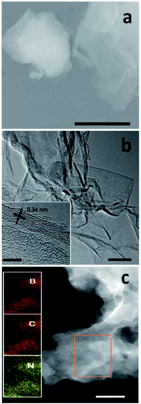 | ||
| Fig. 2 Morphology of 30Glu-Ca sample. (a) SEM image of the 30Glu-Ca sample after the annealing. Scale bar; 2 μm (b) HRTEM image of 30Glu-Ca sample. Scale bar; 50 nm, inset scale bar; 5 nm. (c) TEM dark-field image of 30Glu-Ca sample and the elementary mapping images of B, C and N of the enlargement of selected-area in the picture. Scale bar; 100 nm. | ||
The distance between adjacent fringes reflects the interlayer lattice spacing and its size is ∼0.34 nm which is consistent with the calculated d by XRD analysis for (002) crystal plane.
Elemental mapping throughout the selected area proves the homogeneity of BCN nanosheets with a uniform distribution of B, C and N (Fig. 2c, ESI Fig. 9†).
By the atomic force microscopy (AFM) analysis, the thickness of 30Glu-Ca sample was determined to be 2–4 nm (ESI Fig. 10†), which corresponds to the thickness of 10 stacked layers. Thus, the prepared nanosheets are suitable for optoelectronics because the exciton and charge diffusion length is generally in range of thickness below 10 nm.58
Fig. 3a and c show the ultraviolet-visible diffuse reflectance spectra of xGlu-Ca samples and 20Glu-Me (Me = Mg, Sr, Ba) under UV-visible light irradiation. As shown in Fig. 3a, the increase of the C-doping content makes the absorption edge of samples red-shift.
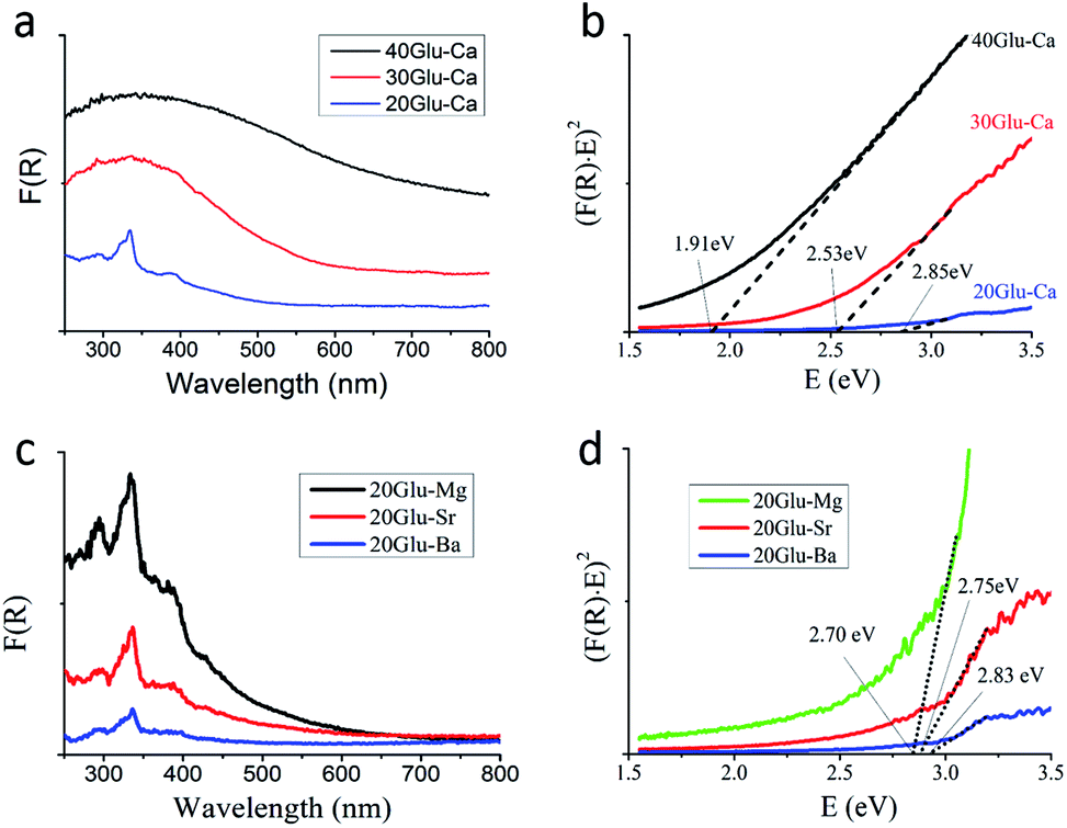 | ||
| Fig. 3 UV-vis spectra of xGlu-Ca and 20Glu-Me samples. (a and c) UV-DRS spectra of xGlu-Ca samples and 20Glu-Me samples. (b and d) Determination of band gap of xGlu-Ca samples and 20Glu-Me samples from the (F(R)E)n versus E plots (n = 2). | ||
From the Tauc plot59 of transformed Kubelka–Munk function versus light energy, the band gap energies of xGlu-Ca (x = 20, 30, 40) samples were 2.85, 2.53 and 1.91 eV (Fig. 3b) and them of 20Glu-Me (Me = Mg, Sr, Ba) samples were 2.70, 2.75 and 2.83 eV, respectively (Fig. 3d, xGlu-Me; ESI Table 4†). And the band gap energy of the prepared h-BN sample was 4.90 eV. (ESI Fig. 11†) The long absorption tails in the visible however indicates the presence of C-doping structures with different energy levels, potentially located at the surface.
Using Mott–Schottky method,9 the conduction band minimum of xGlu-Ca samples were determined to be −1.47, −1.09 and −0.46 eV, respectively (ESI Fig. 12a–c†).
As shown in ESI Fig. 12d,† the band position of the xGlu-Ca (x = 20, 30, 40) gives the possibility for water redox under visible light radiation.
Photocatalytic water splitting
The photocatalytic activity of xGlu-Ca samples and 30Glu-Me (Me = Mg, Sr and Ba) samples for water splitting was determined by H2 evolution and O2 evolution reactions. H2 evolution under light irradiation was observed but in dark wasn't. Fig. 4a and ESI Fig. 12a† shows H2 production of 30Glu-Ca under visible light (with cutoff filter of >420 nm) and under UV-visible light irradiation (without cutoff filter). This sample could evolve H2 from water under visible light illumination even without using noble metal as promoter but its photocatalytic stability is not good. This can be speculated about the over-reduction of the boron sites of surface (corresponds to –NB– structure).10
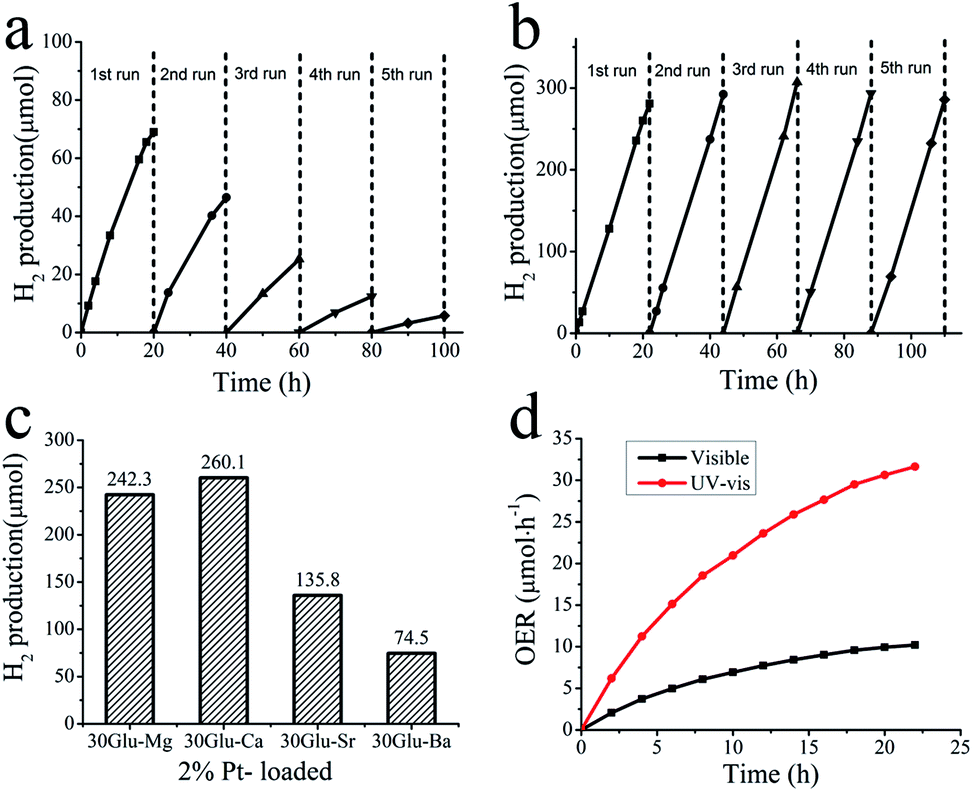 | ||
| Fig. 4 Photocatalytic stability test. (a) Hydrogen evolution from water by pure 30Glu-Ca sample under visible light (λ > 420 nm) irradiation for 100 h. (b) Stable hydrogen evolution from water by 2.0 wt% Pt-loaded 30Glu-Ca under visible light for 110 h. The reaction was continued for many hours with evacuation each run (dashed line). (c) Hydrogen evolution from water by 2.0 wt% Pt-loaded 30Glu-Me (Me = Mg, Ca, Sr and Ba) under visible light for 20 h. (d) Time courses of oxygen production from water by Ni–Co LDHs/30Glu-Ca under visible light (>420 nm) and ultraviolet light illumination. | ||
Among the xGlu-Ca samples, H2 evolution rate of 30Glu-Ca is the highest (ESI Fig. 12c†). As the lower the band gap energy is, the more the charge-carriers produce, H2 evolution rate increase with increase of the doped C-content. But, excess carbon content probably weakens the photocatalytic properties due to nonhomogeneity of the doped carbon and decrease of the charge-carrier lifetime. H2 evolution with 2% Pt-loaded 30Glu-Ca sample is shown in Fig. 4b and ESI Fig. 13b–e.†
Under visible light irradiation, H2 production (260 μmol) evolved for 20 hours with Pt/30Glu-Ca is considerably higher than with pure 30Glu-Ca (69 μmol) and Pt (∼0.5 μmol), and its stability also is remarkably improved. The higher the C-doping content is, the larger the specific surface area is (ESI Table 3†). But the large surface area doesn't improve the H2 evolution rate, which verifies this reaction is mainly limited by charge separation instead of mass transfer.
As shown in Fig. 4c, the 30Glu-Me (Me = Mg, Sr and Ba) samples also evolved H2 under visible light illumination, but their H2 productions were smaller than one of 30Glu-Ca sample. This can be elucidated that 30Glu-Ca sample prepared by calcium borate has the most suitable structure for water splitting compared with samples by other metal borates.
The other half-reaction of water splitting is the oxygen evolution reaction, which is more challenging than the hydrogen evolution reaction. This reaction contains four redox processes over a narrow potential range, multiple proton and electron transfer, and the formation of oxygen–oxygen bond.
Ni–Co layered double hydroxides (Ni–Co LDHs) was used as cocatalyst. As shown in Fig. 4d, Ni–Co LDHs/30Glu-Ca catalyst evolved 10 μmol O2 in 20 hours reaction under visible light and liberated 32 μmol O2 under ultraviolet light. The oxygen evolution proves the above characterization results that xGlu-Ca samples have the band structure suitable for water splitting and Ni–Co LDHs are able to promote O2 evolution with the photogenerated holes (ESI Fig. 14†). The reduction of O2 production in course of time is basically due to the deposition of metallic silver at the catalyst surface, which prevents light absorption and covers active sites.6
Photocatalytic CO2 reduction
CO2 conversion still remain very inefficient, largely owing to insufficient solar light utilization, the high energy barrier for CO2 activation, and the sluggish kinetics of the involved multiple e−/H+ transfer processes.61 As shown above, the prepared BCN nanosheets have a very reductive photoelectron which gives a chance for the direct photocatalytic reduction of CO2.60 The photocatalytic activity of 30Glu-Ca was determined in photocatalytic reduction of CO2 to CO under visible light illumination. As a result, the system evolved CO (30 μmol) and H2 (10 μmol) simultaneously for 10 hours as shown Fig. 5, which were similar to previous research result9 (by BCN prepared at 1250 °C) and the CO selectivity decreased as the water content of the system increased (ESI Fig. 15†).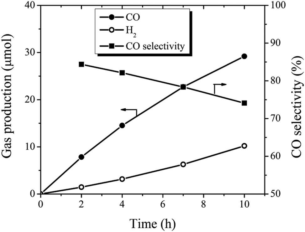 | ||
| Fig. 5 Time conversion and CO selectivity plot for photocatalytic CO2 reduction. | ||
It has been reported that in CO2 reduction by elemental boron catalyst, localized self-hydrolysed boron plays an important role in the activation and adsorption of CO2.62 Here, we guess that not only the boron sites of surface (corresponds to –NB– structure) but also B–O structure act as active sites for CO2 reduction.
Conclusion
The C-doping into h-BN for the photocatalytic activity under visible light irradiation was successfully achieved at low annealing temperature (1000 °C) by adding alkaline earth metal compounds. The added alkaline earth metal compounds promotes the formation of BCN nanosheets in the melt-phase of MeO–2B2O3. The prepared BCN nanosheets possess tuneable band gap and the capability for photocatalytic water splitting and CO2 reduction under visible light. The simulation of the formation process of BCN nanosheets in MeO–2B2O3 melt based on solubility of each elements, the further structure optimization of BCN nanosheets, the effects of alkaline metal compounds and the doping of other elements into h-BN by this method can be expected for development of 2D BN-based photocatalyst.Conflicts of interest
There are no conflicts to declare.Acknowledgements
We acknowledge financial support from National Key Basic Research Program of China (2014CB931801 and 2016YFA0200700, Z. Y. T.), National Natural Science Foundation of China (51772957, Y. G.; 21721002 and 21475029, Z. Y. T.), Frontier Science Key Project of Chinese Academy of Sciences (QYZDJ-SSW-SLH038, Z. Y. T.), “Strategic Priority Research Program” of Chinese Academy of Sciences (XDA09040100, Z. Y. T.), and K. C. Wong Education Foundation (Z. Y. T.). The authors also gratefully acknowledge the support of Youth Innovation Promotion Association CAS and CAS-TWAS president's fellowship.References
- N. Zhang, R. Ciriminna, M. Pagliaro and Y. J. Xu, Chem. Soc. Rev., 2014, 43, 5276–5287 RSC.
- S. Liu, Z.-R. Tang, Y. Sun, J. C. Colmenares and Y.-J. Xu, Chem. Soc. Rev., 2015, 44, 5053–5075 RSC.
- H. Kato, K. Asakura and A. Kudo, J. Am. Chem. Soc., 2003, 125, 3082–3089 CrossRef CAS PubMed.
- K. Maeda, K. Teramura, D. Lu, T. Takata, N. Saito, Y. Inoue and K. Domen, Nature, 2006, 440, 295 CrossRef CAS PubMed.
- Y. Li, H. Xu, S. Ouyang and J. Ye, Phys. Chem. Chem. Phys., 2016, 18, 7563–7572 RSC.
- A. Thomas, K. Takanabe, G. Xin, J. M. Carlsson, K. Domen and M. Antonietti, Nat. Mater., 2009, 8, 76–80 CrossRef PubMed.
- R. Kuriki, K. Sekizawa, O. Ishitani and K. Maeda, Angew. Chem., Int. Ed., 2015, 54, 2406–2409 CrossRef CAS PubMed; X. Chen, S. Shen, L. Guo and S. S. Mao, Chem. Rev., 2010, 110, 6503–6570 CrossRef PubMed.
- A. Iwase, S. Yoshino, T. Takayama, H. N. Yun, R. Amal and A. Kudo, J. Am. Chem. Soc., 2016, 138, 10260–10264 CrossRef CAS PubMed; A. Kudo and Y. Miseki, Chem. Soc. Rev., 2009, 38, 253–278 RSC.
- C. Huang, C. Chen, M. Zhang, L. Lin, X. Ye, S. Lin, M. Antonietti and X. Wang, Nat. Commun., 2015, 6, 7698 CrossRef PubMed.
- X. Fan, Z. Shen, A. Q. Liu and J. L. Kuod, Nanoscale, 2012, 4, 2157–2165 RSC.
- M. Zhang, G. Gao, A. Kutana, Y. Wang, X. Zou, J. S. Tse, B. I. Yakobson, H. Li, H. Liu and Y. Ma, Nanoscale, 2015, 7, 12023–12029 RSC.
- A. K. Geim and K. S. Novoselov, Nat. Mater., 2007, 6, 183–191 CrossRef CAS PubMed.
- D. Golberg, Y. Bando, Y. Huang, T. Terao, M. Mitome, C. Tang and C. Zhi, ACS Nano, 2010, 4, 2979–2993 CrossRef CAS PubMed.
- A. Y. Liu, R. M. Wentzcovitch and M. L. Cohen, Phys. Rev. B, 1989, 39, 1760–1765 CrossRef CAS.
- M. Bernardi, M. Palummo and J. C. Grossman, Phys. Rev. Lett., 2012, 108, 226805 CrossRef PubMed.
- M. S. C. Mazzoni, R. W. Nunes, S. Azevedo and H. Chacham, Phys. Rev. B, 2006, 73, 073108 CrossRef.
- Y. Y. Liu, S. Bhowmick and B. I. Yakobson, Nano Lett., 2011, 11, 3113–3116 CrossRef CAS PubMed.
- J. D. Martins and H. Chacham, ACS Nano, 2011, 5, 385–393 CrossRef CAS PubMed.
- H. Nozaki and S. Itoh, Phys. Rev. B, 1996, 53, 14161–14170 CrossRef CAS.
- P. Sutter, R. Cortes, J. Lahiri and E. Sutter, Nano Lett., 2012, 12, 4869–4874 CrossRef CAS PubMed.
- V. L. Solozhenko, Properties of Group III Nitrides, EMIS Data-reviews Series, N11, ed. J. H. Edgar, INSPEC, 1994, pp. 43–70 Search PubMed.
- I. Savvatimskiy, Carbon, 2005, 43, 1115 CrossRef.
- O. Hod, J. Chem. Theory Comput., 2012, 8, 1360–1369 CrossRef CAS PubMed.
- M. O. Watanabe, S. Itoh, T. Sasaki and K. Mizushima, Phys. Rev. Lett., 1996, 77, 187–189 CrossRef CAS PubMed.
- Y. Chen, J. C. Barnard, R. E. Palmer, M. O. Watanabe and T. Sasaki, Phys. Rev. Lett., 1999, 83, 2406–2408 CrossRef CAS.
- L. Ci, L. Song, C. Jin, D. Jariwala, D. Wu, Y. Li, A. Srivastava, Z. F. Wang, K. Storr, L. Balicas, F. Liu and P. M. Ajayan, Nat. Mater., 2010, 9, 430–435 CrossRef CAS PubMed.
- J. Lu, K. Zhang, X. F. Liu, H. Zhang, T. C. Sum, A. H. C. Neto and K. P. Loh, Nat. Commun., 2013, 4, 2681 CrossRef PubMed.
- W. H. Lee, H. N. Yang, K. W. Park, B. S. Choi, S. C. Yi and W. J. Kim, Energy, 2016, 96, 314–324 CrossRef CAS.
- Y. Zheng, Y. Jiao, L. Ge, M. Jaroniec and S. Z. Qiao, Angew. Chem., Int. Ed., 2013, 52, 3110–3116 CrossRef CAS PubMed.
- J. Wang, J. Hao, D. Liu, S. Qin, D. Portehault, Y. Li, Y. Chen and W. Lei, ACS Energy Lett., 2017, 2(2), 306–312 CrossRef CAS.
- M. Favaro, L. Ferrighi, G. Fazio, L. Colazzo, C. D. Valentin, C. Durante, F. Sedona, A. Gennaro, S. Agnoli and G. Granozzi, ACS Catal., 2015, 5, 129–144 CrossRef CAS.
- S. Umrao, T. K. Gupta, S. Kumar, V. K. Singh, M. K. Sultania, J. H. Jung, I. K. Oh and A. Srivastava, ACS Appl. Mater. Interfaces, 2015, 7, 19831–19842 CrossRef CAS PubMed.
- D. Deng, K. S. Novoselov, Q. Fu, N. Zheng, Z. Tian and X. Bao, Nat. Nanotechnol., 2016, 11, 218–230 CrossRef CAS PubMed.
- Y. Shi, C. Hamsen, X. Jia, K. K. Kim, A. Reina, M. Hofmann, A. L. Hsu, K. Zhang, H. Li, Z. Y. Juang, M. S. Dresselhaus, L. J. Li and J. Kong, Nano Lett., 2010, 10, 4134–4139 CrossRef CAS PubMed.
- L. Qin, J. Yu, S. Kuang, C. Xiao and X. Bai, Nanoscale, 2012, 4, 120–123 RSC.
- K. Yuge, Phys. Rev. B, 2009, 79, 144109 CrossRef.
- M. R. Uddin, J. Li, J. Y. Lin and H. X. Jiang, J. Appl. Phys., 2015, 117, 215703–215707 CrossRef.
- H. E. Çamurlu, N. Sevinç and Y. Topkaya, J. Eur. Ceram. Soc., 2008, 28, 679–689 CrossRef.
- W. Lei, D. Portehault, R. Dimova and M. Antonietti, J. Am. Chem. Soc., 2011, 133, 7121–7127 CrossRef CAS PubMed.
- R. Geick, C. H. Perry and G. Rupprecht, Phys. Rev., 1966, 146, 543–547 CrossRef CAS.
- X. Yu and L. Qiang, Adv. Mater. Phys. Chem., 2012, 2, 63–68 CrossRef CAS.
- L. L. Tan, W. J. Ong, S. P. Chai and A. R. Mohamed, Nanoscale Res. Lett., 2013, 8, 465 CrossRef PubMed.
- J. Yu, L. Qin, Y. Hao, S. Kuang, X. Bai, Y. M. Chong, W. Zhang and E. Wang, ACS Nano, 2010, 4, 414–422 CrossRef CAS PubMed.
- M. Erfani, E. Saion, N. Soltani, M. Hashim, W. Saffiey, B. W. Abdullah and M. Navasery, Int. J. Mol. Sci., 2012, 13, 14434–14445 CrossRef CAS PubMed.
- Z. S. Hu, R. Lai, F. Lou, L. G. Wang, Z. L. Chen, G. X. Chen and J. X. Dong, Wear, 2002, 252, 370–374 CrossRef CAS.
- T. I. Korshikova, S. V. Parkhomenko, A. V. Tolmachev, V. A. Tsurikov and R. P. Yavetskiy, Inorg. Mater., 2008, 44(12), 1345–1348 CrossRef CAS.
- S. A. M. Abdel-Hameed, N. A. Ghoniem, E. A. Saad and F. H. Margha, Ceram. Int., 2005, 31, 499–505 CrossRef CAS.
- E. M. Levin, C. R. Robbins and H. F. McMurdie, Phase Diagrams for Ceramists, The American Ceramic Society, Ohio, 1964 Search PubMed.
- T. Mutluer and M. Timucin, J. Am. Ceram. Soc., 1975, 58(2), 196–197 CrossRef CAS.
- C. F. Chenot, J. Am. Ceram. Soc., 1967, 50(2), 117–118 CrossRef CAS.
- B. Meshalkin and A. B. Kaplun, J. Cryst. Growth, 2005, 275, e301–e305 CrossRef.
- A. Nagashima, N. Tejima, Y. Gamou, T. Kawai and C. Oshima, Surf. Sci., 1996, 357–358, 307–311 CrossRef CAS.
- A. Pakdel, Y. Bando, D. Shtansky and D. Golberg, Surf. Innovations, 2013, 1, 32–39 CrossRef CAS.
- F. L. Huang, C. B. Cao, X. Xiang, R. T. Lv and H. S. Zhu, Diamond Relat. Mater., 2004, 13, 1757–1760 CrossRef CAS.
- X. Liu, Y. Gao, M. Zhang, X. Zhang, S. Wang and B. Feng, RSC Adv., 2015, 5, 52452–52458 RSC.
- S. Y. Kim, J. Park, H. C. Choi, J. P. Ahn, J. Q. Hou and H. S. Kang, J. Am. Chem. Soc., 2007, 129, 1705–1716 CrossRef CAS PubMed.
- S. R. Forrest, MRS Bull., 2005, 30, 28–32 CrossRef CAS.
- J. Tauc, R. Grigorovici and A. Vancu, Phys. Status Solidi, 1966, 15, 627 CrossRef CAS.
- T. M. L. Wigley, R. Richels and J. A. Edmonds, Nature, 1996, 379, 240–243 CrossRef CAS.
- W. Tu, Y. Zhou and Z. Zou, Adv. Mater., 2014, 26, 4607–4626 CrossRef CAS PubMed.
- G. Liu, X. Meng, H. Zhang, G. Zhao, H. Pang, T. Wang, P. Li, T. Kako and J. Ye, Angew. Chem., Int. Ed., 2017, 56, 5570–5574 CrossRef CAS PubMed.
- S. Wang and X. Wang, Angew. Chem., Int. Ed., 2016, 55, 2308–2320 CrossRef CAS PubMed.
Footnotes |
| † Electronic supplementary information (ESI) available. See DOI: 10.1039/c8ra07583b |
| ‡ These three authors contributed equally to this work. |
| This journal is © The Royal Society of Chemistry 2018 |