
 Open Access Article
 This Open Access Article is licensed under a Creative Commons Attribution-Non Commercial 3.0 Unported Licence
pH-responsive chitosan-based flocculant for precise dye flocculation control and the recycling of textile dyeing effluents†
Tingting Weia,
Liang Wub,
Feng Yu a,
Yin Lva,
Long Chena,
Yulin Shi*a and
Bin Dai*a
a,
Yin Lva,
Long Chena,
Yulin Shi*a and
Bin Dai*a
aKey Laboratory for Green Processing of Chemical Engineering of Xinjiang Bingtuan, School of Chemistry and Chemical Engineering, Shihezi University, Shihezi 832003, P. R. China. E-mail: shiyulin@shzu.edu.cn; Db_tea@shzu.edu.cn
bChongqing Daxin Pharmaceutical Co., Ltd, Chongqing 400714, P. R. China
First published on 26th November 2018
Abstract
In this work, we introduce a simple and effective method for the controlled release of dye from dye saturation flocs by a well-designed pH responsive chitosan-based flocculant. The dye flocculation capacities could be precisely controlled from 0.5 to 2 g g−1 by simply adjusting the pH of the desorption solution. A series of flocs with different dye flocculation capacities was prepared and used as nitrogen-rich precursors to prepare nitrogen-doped carbon materials through one-step carbonization. The results demonstrate that the specific surface areas, pore structures and supercapacitance performance of the resulting N-doped carbon materials could be readily controlled by varying the dye flocculation capacity. By using a dye sludge floc with an appropriate dye flocculation capacity (1.5 g g−1) as a precursor, the resulting N-doped material exhibited a high specific capacity and good cycling performance for a supercapacitor electrode. The unique pH-responsive properties of the chitosan-based flocculant facilitated easy tuning of the surface cationic degree and deprotonation behavior by varying pH. This work presents a new concept for balancing between environmental capacity and energy capacity using a smart pH-responsive carrier system based on modified chitosan, which is highly promising for the recycling of industrial wastewater to produce energy materials.
1. Introduction
Dyeing processes consume large amounts of synthetic dyestuffs and pigments in the textile industries. Substantial fractions of dyes (5–50%) are wasted and discharged in wastewater due to the low fixation rates on textile fibers or dye hydrolysis during the dyeing process.1 Dyes exhibit a wide range of chemical structures, primarily based on azo compounds that have one or more azo bonds (–N![[double bond, length as m-dash]](https://www.rsc.org/images/entities/char_e001.gif) N–) in their molecular structure.2 Azo dyes with undesirable colors are highly soluble in water ecosystems, and even at very low concentrations, they may cause serious environmental problems. Furthermore, azo dyes are potentially toxic to humans and aquatic life.
N–) in their molecular structure.2 Azo dyes with undesirable colors are highly soluble in water ecosystems, and even at very low concentrations, they may cause serious environmental problems. Furthermore, azo dyes are potentially toxic to humans and aquatic life.
The coagulation–flocculation process is a commercially available technology that has been widely used in industry to treat dye-containing effluents. Commercial organic flocculants are classified as natural or synthetic water-soluble polymers.3 Among them, chitosan, a natural polycation, is an interesting candidate because of its abundance, low-cost, high-efficiency and lack of secondary pollution.4 Many hazardous pollutants, such as organic dyes and heavy metal ions, can be removed from aqueous solutions either by sorption onto water-insoluble chitosan adsorbent or by flocculation using acid-dissolved chitosan.5,6 Natural chitosan has a relatively lower molecular weight and poor water solubility, which are the major drawbacks during water treatment processes. Chemically modified chitosan has been developed to enhance removal of environmental pollutants from wastewater. Etherification/amination and graft copolymerization are the most widely used chemical modification methods to improve the physicochemical properties of native chitosan for water treatment.7,8
In general, the flocculating mechanisms by which dissolved dyes in wastewater are destabilized include double layer compression, charge neutralization, adsorption and particle–polymer–particle bridges.9 Therefore, polymeric flocculants can generate large volumes of dense and compact sludge flocs, even with an extremely small amount of flocculant, which can then be treated by solid–liquid separation. Flocculation is a most important and effective technology, and it has been extensively used for wastewater treatment in the textile industry, but it produces a large quantity of very toxic sludge. So, we can say that the coagulation–flocculation process plays an important role in transporting toxic dye from the aquatic environment into solid waste, a more treatable form, but it does not entirely eliminate the potential risks of dye. It is a fact that printing and dyeing enterprises are now facing increasing pressure from regulatory agencies in the handling, treatment and disposal of colored flocculation sludge.
Supercapacitors, the most promising energy storage devices, have attracted much attention because of their high power densities, long cycle life, and fast and efficient charge propagation. To further develop high energy density and specific power supercapacitors, the use of electrode materials possessing pseudo-active species is a vital factor to ensure high capacity and high electrical conductivity.10 So far, one of the most critical approaches in the development of high-capacitance materials has been to incorporate heteroatoms into carbon frameworks. Rich nitrogen doping seems to be the most promising method for significantly improved electrochemical performance and catalytic activities.11,12
Textile dyeing effluents are a naturally rich source of nitrogen (azo dyes), and are an attractive N-containing precursor to produce nitrogen-doped carbon materials through the direct carbonization method. However, despite the outstanding electrochemical performance of N-doped carbon derived from sewage sludge,13 there are still some problems. The mass ratio of carbon source and nitrogen source in sludge has a narrow acceptable interval, which is hypothesized to affect the electrochemical performance of the resulting N-doped carbon materials for the late-stage carbonization of sludge flocs. It is generally recognised that the electrochemical characteristics of nitrogen-doped carbon materials are closely related to nitrogen content, defect densities, nitrogen species proportion and pore structure, and variation in the final carbon products is determined by the nitrogen amount in the starting nitrogen-rich precursor.14 The nitrogen content in a precursor can usually be controlled by adjusting the mass ratio of the carbon and nitrogen sources.15 However, the main disadvantage of flocculation with a polymeric flocculant is that the flocculation window (optimum dosage) is very narrow, since even a small increase of the polymer dose can restabilize the system (flocculant overdose), subsequently influencing the efficiency of flocculation.
Considering both the environment and energy capacities, the recycling of textile dyeing effluents faces two major challenges: (i) ensuring that the dosage of flocculant is in the optimal range, because color can be effectively removed from wastewater, and (ii) synthesizing N-doped carbon materials by direct pyrolysis of precursor sludge with high electrochemical performance. In this study, pH-responsive chitosan derivative was synthesized and utilized as a cationic flocculant to remove anionic azo dye from dyeing waste water. The dye flocculation capacity was adjusted by a pH-controlled open/closed flocculant for dye release. Flocs with different flocculation capacities (0–99%) were used as nitrogen-rich precursors to prepare nitrogen-doped carbon materials through one-step carbonization. The unique pH-responsive properties of the chitosan-based flocculant facilitated easy tuning of the surface cationic degree and deprotonation behavior by varying pH, which enabled a balance between environmental capacity (color removal efficiency in wastewater) and energy capacity (specific capacitance as a supercapacitor electrode); that is, with higher color removal efficiency from textile dyeing effluents, and, at the same time, the synthesis of nitrogen-doped materials with the best electrochemical performance from the sludge (Scheme 1).
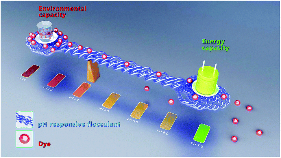 | ||
| Scheme 1 Balance between environmental capacity and energy capacity using a pH-responsive flocculation system. | ||
2. Experimental section
2.1 Materials and reagents
Chitosan (75–85% deacetylated) and dimethylamine were obtained from Sinopharm Chemical Reagent Co., Ltd. Cyanuric chloride was purchased from Tokyo Chemical Industry Co., Ltd. 2,4-Bis(dimethylamino)-6-chloro-[1,3,5]-triazine (BDAT) was synthesized from cyanuric chloride and dimethylamine according to previous reports.16 Azo dye Reactive Brilliant Red K-2BP (K-2BP, λmax = 511 nm, structure as shown in ESI Fig. S1†), a commercially available and widely used reactive dye, was obtained from Longsheng Dyestuff Co., Ltd. K-2BP was hydrolyzed and purified before use to simulate actual dyeing effluent. All other chemicals were of analytical grade and used as received. Distilled water was used in all experiments, including those for the dye flocculation/release process.2.2 Preparation of chitosan-based flocculant
Chitosan-based flocculant (CBF) was prepared by etherification of chitosan using BDAT as the cationic etherifying agent according to our previous research.17 The synthetic route is shown in ESI Fig. S2.† In a typical preparation, chitosan (3.6 g), sodium hydroxide (3.1 g) and BDAT (15 g) were added to a four-neck flask. Next, dimethyl sulfoxide (200 mL) was added under vigorous stirring. Then, this mixture was slowly heated to 130 °C under vigorous stirring and a nitrogen gas atmosphere for 8 h. The product was isolated and purified by acetone to remove unreacted cationic etherifying agent. The etherification of chitosan with BDAT was confirmed by FTIR (ESI Fig. S3†). The substitution degree of CBF was calculated from the nitrogen content (N) determined by elemental analysis (ESI Table S1†).2.3 Azo dye flocculation and sludge floc preparation
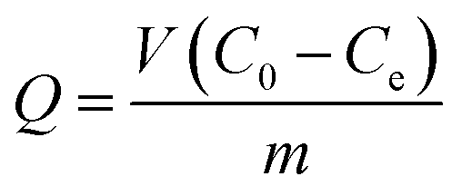
Dye flocculation experiments were conducted using batch tests in a 100 mL beaker (see Methods and Experimental section in ESI† for details). Specifically, at the optimum dose of flocculant, 0.0375 g L−1, with an initial dye solution pH of 1.5, the color removal was maximized (R > 99%). The subsequent tests for the controlled release of dye were carried out under different pH values. Briefly, the dye-loaded sludge floc was separated and placed in a beaker, 100 mL of water was added, and the mixture was stirred at a constant speed of 150 rpm. Cumulative dye release from flocs was determined from the calibration curve using UV-visible spectrophotometry at λmax (ESI Fig. S4†). The sludge floc was collected and dried to a constant weight by vacuum at 70 °C. The color removal (R%) and dye flocculation capacity Q (g g−1) were calculated as follows:
 | (1) |
 | (2) |
2.4 Synthesis of N-doped porous carbon from sludge flocs
N-doped carbon materials were obtained from the sludge flocs with different dye flocculation capacities, which were denoted as CBF–N-x (x = 0.5–2). Typically, dry sludge flocs were placed in a pipe furnace and heated at 800 °C for 3 h, with a heating rate of 5 °C min−1 under an N2 atmosphere. The black powder was then dispersed in HCl solution (1 M), while stirring to remove the inorganic compounds. After filtration, the products were washed with distilled water until the pH reached 7, and then they were dried at 105 °C before further study.2.5 Characterization of materials
The C, H, and N elemental content of CBF was measured with an elemental analyzer (Vario EL, Germany). The zeta potential characterization (ZP) of the CBF solution was measured in a Nanoplus zeta/nano particle analyzer (Otsuka Electronics, Japan). The optical transmittance of the CBF solution was measured at 590 nm using a Cary 300 Bio UV-visible spectrophotometer (Varian Inc., CA, USA) with a glass cell. The cumulative release of dye from sludge flocs was tracked at 511 nm using a Cary 300 Bio UV-visible spectrophotometer (Varian Inc., CA, USA). The crystalline structure of CBF–N-x samples was determined by X-ray diffraction (Rigaku, Ultima IV, Japan) using Cu-Kα radiation. X-ray photoelectron spectroscopy (XPS) data were recorded using an ESCALAB 250Xi system from Thermo Scientific. The pore properties of CBF–N-x were determined by measuring volumetric N2 adsorption–desorption isotherms at liquid nitrogen temperature using the Micromeritics ASAP 2020 HD88 instrument (Micromeritics, USA). The Raman spectra of carbon powders were obtained from 200 to 2000 cm−1 using a 325 nm argon ion laser in a Renishaw inVia Reflex Raman spectrometer (Renishaw Instruments, UK).2.6 Electrochemical measurements
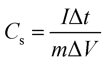
Electrochemical tests of the electrodes were carried out using a Chenhua CHI 760D model Electrochemical Workstation (Shanghai, China). CBF–N-x was brush-coated onto two sides of a nickel foam to serve as the working electrode in a standard three-electrode electrochemical setup at room temperature. Electrochemical impedance spectroscopy (EIS) spectra were recorded over the frequency range from 1 MHz to 1 mHz, at an open circuit potential, with 5 mV AC amplitude. Cyclic voltammetry (CV) and galvanostatic charge–discharge (GCD) curves were obtained at different scan rates of 5–50 mV s−1 over the potential range from 0 to −1 V. The electrochemical stability test was performed by repeating the charge/discharge test at a current density of 5 A g−1 for 5000 cycles. The specific capacitance (Cs) was measured from the GCD curves according to eqn (3):
 | (3) |
3. Results and discussion
3.1 pH-responsive flocculant for a precise dye release control system
In our previous work,18,19 we developed controlled contaminant capture and release in wastewater using pH-responsive flocculants. In this work, we introduce a simple method for controlled dye release from dye-loaded flocs by well-designed pH-responsive CBF, and combined with the carbonization of flocs, this method makes it possible to effectively realize the control of element content and pore structure in the as-prepared N-doped carbon materials (Fig. 1a). The cationic etherifying agent BDAT is a weak base containing two tertiary amine groups that are easily protonated in acidic medium and deprotonated in alkaline medium. Therefore, CBF can dissolve in water at low pH via the positive charges carried by the protonated amine groups, and charge neutralization can occur between the cationic amine and anionic dye ions (–SO3−), forming insoluble flocs.20 With an increase in solution pH, the BDAT segments in the CBF are progressively deprotonated and electrostatic forces between CBF and dye molecules are weakened, which facilitates release of dye molecules from flocs.7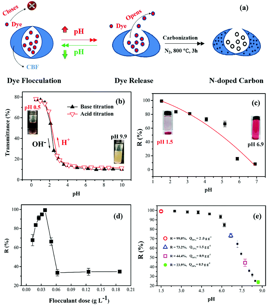 | ||
| Fig. 1 pH-responsive flocculant for a precise dye release control system. (a) Overall synthesis route to prepare CBF–N-x using dye sludge flocs as precursors. UV-visible transmittance (b) and dye color removal (c) for CBF at different pH values. (d) Effect of dose of CBF on color removal. (e) Cumulative release profile of dye from dye-loaded flocculant under different pH values. | ||
The reversible optical transmittance change of CBF dispersions was demonstrated by UV-visible transmittance measurements (590 nm) with pH from 0.5 to 10 at 25 °C, and the results are shown in Fig. 1b. CBF was soluble in acidic solutions via the positive charges carried by the protonated amine groups on the units of chitosan. Therefore, chain–chain repulsion increased with decreasing solution pH due to the higher cation density,21 which may be responsible for the higher transmittance for CBF solution at lower pH. We can see that the transmittance was close to 80%, and the zeta potential remained at 26 mv (ESI Fig. S5†) at pH 1. Thus, a remarkable reduction in color was observed at the lower flocculation pH (Fig. 1c). As the pH increased, the optical transmittance and color removal decreased during the acid–base titration. Soluble quaternary ammonium salt segments formed in the CBF were progressively deprotonated and neutralized. CBF formed a compact conformation, which yielded large assemblies via hydrophobic interactions (s-triazine ring) in solution to induce polymer aggregation and phase separation.22 Therefore, by introducing BDAT into chitosan, the degree of protonation, surface charge and color removal on CBF could be controlled by various pH values.
 | ||
| Fig. 2 (a) N2 adsorption–desorption isotherms and (b) pore size distributions of CBF–N-x. | ||
Fig. 1d demonstrates the effect of flocculant dose on the color removal at optimum pH. A narrow flocculation window in the dose–removal curve could be observed when the concentration of flocculant was increased. The removal rate of K-2BP was more than 99% at the optimum dose (0.0375 g L−1) with pH 1.5. When the effective concentration of flocculant reached the required dose level, the negative charges of the sulfonate groups of dye were completely neutralized by the cationic flocculant, and the maximum removal of dye was achieved. This makes the cost more feasible at an industrial scale, since a minimum flocculant dosage is required. From another aspect, an optimal flocculant dosage reduced the total quantity of solid waste disposed, since synthetic chemical flocculant consumption was reduced to a minimum. However, when the flocculant dosage was increased, the color removal decreased rapidly from 99.3% to 33.5%. The lower dye removal efficiency with flocculant overdosing was most likely related to negative restabilization.23,24 The surface charge of colloidal particles was further reversed from negative to positive because of greater numbers of excessive cations, and chain repulsion between positive charge residues on the polymer side chains resulted in restabilization of the dye suspension colloids, subsequently decreasing the dye removal efficiency.
Fig. 1e demonstrates the cumulative release profile of dye from dye-loaded flocculant under different pH values. As expected, remarkable dye release occurred under different pH values until a balanced concentration was reached. Clearly, the release of dye from flocs increased with the increasing pH of the desorption solution. These dye release behaviors were attributed to the progressive deprotonation of amine groups on the chitosan chain caused by increasing the pH of the medium. CBF contains ionizable amine groups that can accept and donate protons, the driving force for solubilization and precipitation, and they are also associated with the cumulative dye release rate. As pH continued to decrease to 8.7, the flocculant was progressively deprotonated, which weakened the electrostatic interactions of the dye. As a result, cumulative dye release from the flocs was increased in response to increased pH. As can been seen, when the pH varied from 1.5 to 8.5, the total cumulative release of dye from flocs reached 26.8% (pH = 6.6), 55.6% (pH = 7.7), or 76.1% (pH = 8.7). Therefore, sludge flocs with different dye flocculation capacity Q values (Q = 0.5, 0.9, 1.5, 2.0 g g−1), were prepared and denoted as CBF-x (x = 0.5, 0.9, 1.5, 2.0). Then, sludge flocs were used as a precursor to prepare nitrogen-doped carbon materials (denoted as CBF–N-x).
3.2 Characterization of the N-doped carbon materials
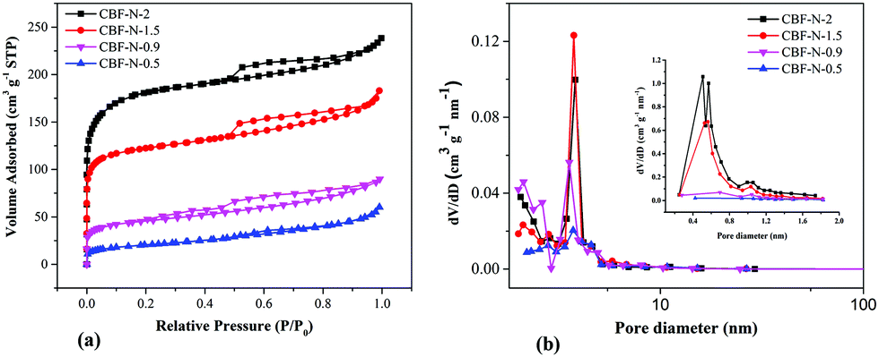
N2 adsorption–desorption isotherms of CBF–N-x for various samples with x = 0.5, 0.9, 1.5, and 2.0 are demonstrated in Fig. 2a. The specific surface area (SBET) and pore structure parameters of CBF–N-x are listed in ESI Table S2.† The pore structure of the resulting annealed products was surprisingly adjusted by tuning the mass ratio of dye to flocculant. Nitrogen adsorption–desorption isotherms of the sample CBF–N-x obviously exhibited a type IV profile with a distinct H1-type hysteresis loop at a higher relative pressure range. The SBET of the resulting N-doped carbon materials was enlarged with the increased dye content. As the dye flocculation capacity increased to 0.5, 0.9, 1.5, and 2.0 g g−1, SBET was measured to be 73.2, 163.7, 440.4 and 649.5 m2 g−1, respectively.The pore size distribution (PSD) was calculated using the BJH model on the adsorption isotherm branches, as shown in Fig. 2b. As the amount of added dye increased from 0.5 to 2 g g−1, the mesopores gradually centered at the 3.2–4.2 nm region. Therefore, a series of N-doped carbon materials, with controlled pore structures, were obtained by tuning the amount of dye adsorbed on flocculant. CBF–N-1.5 contained a relatively greater number of mesopores (3.2–5.1) than CBF–N-2 and other samples. The present high volume of mesopores was important to accelerate the diffusion of ions and double layer charging/discharging with the electrodes.25,26
The XPS technique was used to further probe a more precise chemical identification of the heteroatoms in the surface of CBF–N-x. The XPS survey spectra show C 1s, N 1s, and O 1s peaks in the CBF–N-x samples (Fig. 3a). Furthermore, the precise N content of the CBF–N-x was confirmed by elemental analysis (ESI Table S3†). The content of N was 6.58, 7.19, 9.57 and 8.5 wt% for CBF–N-0.5, CBF–N-0.9, CBF–N-1.5 and CBF–N-2, respectively. These results show that CBF–N-1.5 possesses relatively higher nitrogen content than the other samples. More importantly, the final nitrogen content of the N-doped carbon materials could be readily controlled by varying the dye flocculation capacity. The N 1s XPS spectra of CBF–N-x (Fig. 3b and ESI Fig. S6†) show the formation of the four different types of N, including pyridine-N-oxide (403.7 eV), graphitic nitrogen (401.2 eV), pyrrolic nitrogen (400.3 eV) and pyridinic nitrogen (398.6 eV).27 Notably, relatively higher graphitic nitrogen (28.6 at%) and pyridine-N-oxide nitrogen (19.7 at%) content in the CBF–N-1.5 was detected by high-resolution XPS. Introducing the positive charges of graphitic nitrogen and pyridine-N-oxide into carbon materials is beneficial for the transfer of electrons through the carbon.28 The C 1s XPS spectra of CBF–N-x (Fig. 3c and ESI Fig. S7†) were fitted by four peaks, corresponding to CC–C (284.7 eV), C–N/C–O (285.6 eV), CO (288.1 eV), and π–π* (291.1 eV). The CC bonds of the CBF–N-1.5 accounted for up to 53.3 at% of the content, which was much higher than that for CBF–N-0.5 (49.6 at%), CBF–N-0.9 (45.5 at%) and CBF–N-2 (52.5 at%). Previous studies demonstrated that plentiful accessible CC bonds facilitated electron mobility, which contributed to lower resistivity for electrodes.29 In addition, the elemental mapping images of CBF–N-1.5 demonstrated the presence of O, C, and N elements and uniform dispersion on the surface of nanosheets (ESI Fig. S8†), suggesting the successful preparation of nitrogen-doped carbon materials using sludge flocs as the precursor materials.
 | ||
| Fig. 3 XPS survey spectra of CBF–N-x (a), high-resolution XPS deconvoluted spectra of N 1s (b) and C 1s (c) peaks of CBF–N-1.5. | ||
The degree of graphitization of CBF–N-x was further investigated by XRD and Raman spectroscopy. Two peaks, located at approximately 23° and 43° in the wide-angle XRD profiles of CBF–N-x (Fig. 4a), corresponded to the (002) and (100) planes of graphitic carbon.30 The Raman spectra of CBF–N-x (Fig. 4b) revealed a pair of peaks centered at 1601 cm−1 and 1360 cm−1, namely D (related to disorderly carbon) and G (related to graphitic carbon) bands, respectively.31 The intensity ratio of these two peaks (IG/ID) is related to the extent of graphitization. It is noteworthy that a higher IG/ID ratio (≥0.95) is observed for these samples, indicating that CBF–N-x have comparably higher graphitization levels. These results were consistent with the XRD results. CBF–N-x are composed of graphitic structures, which greatly enhance electrical conductivity between the electrolyte species and electrode surfaces.
 | ||
| Fig. 4 XRD patterns (a), and Raman spectra (b) of CBF–N-x. | ||
3.3 Electrochemical performance of the N-doped carbon materials
Fig. 5a shows the CV curves of CBF–N-x (x = 0.5, 0.9, 1.5, 2.0) at the same scan rate, 20 mV s−1. The maximum integration area of the CV curve was apparent for CBF–N-1.5, indicating that the moderate ratio of dye to flocculant played an important role in preparing material with the desirable capacitance. Different dye uptakes followed the same trend with respect to the galvanostatic charge/discharge curves at the same current density (Fig. 5b). The Cs of CBF–N-x was dramatically increased with increasing dye uptakes from 0.5 to 2 g g−1. When the dye uptake reached 1.5 g g−1, Cs reached a maximum (144 F g−1) at current density of 0.5 A g−1, indicating that the specific capacitance for CBF–N-x was primarily affected by the dye uptake amount. CBF–N-1.5 had high specific capacitance that was mainly attributed to the high specific surface area and appropriate PSD, which facilitated the diffusion of electrolyte ions across the electrode.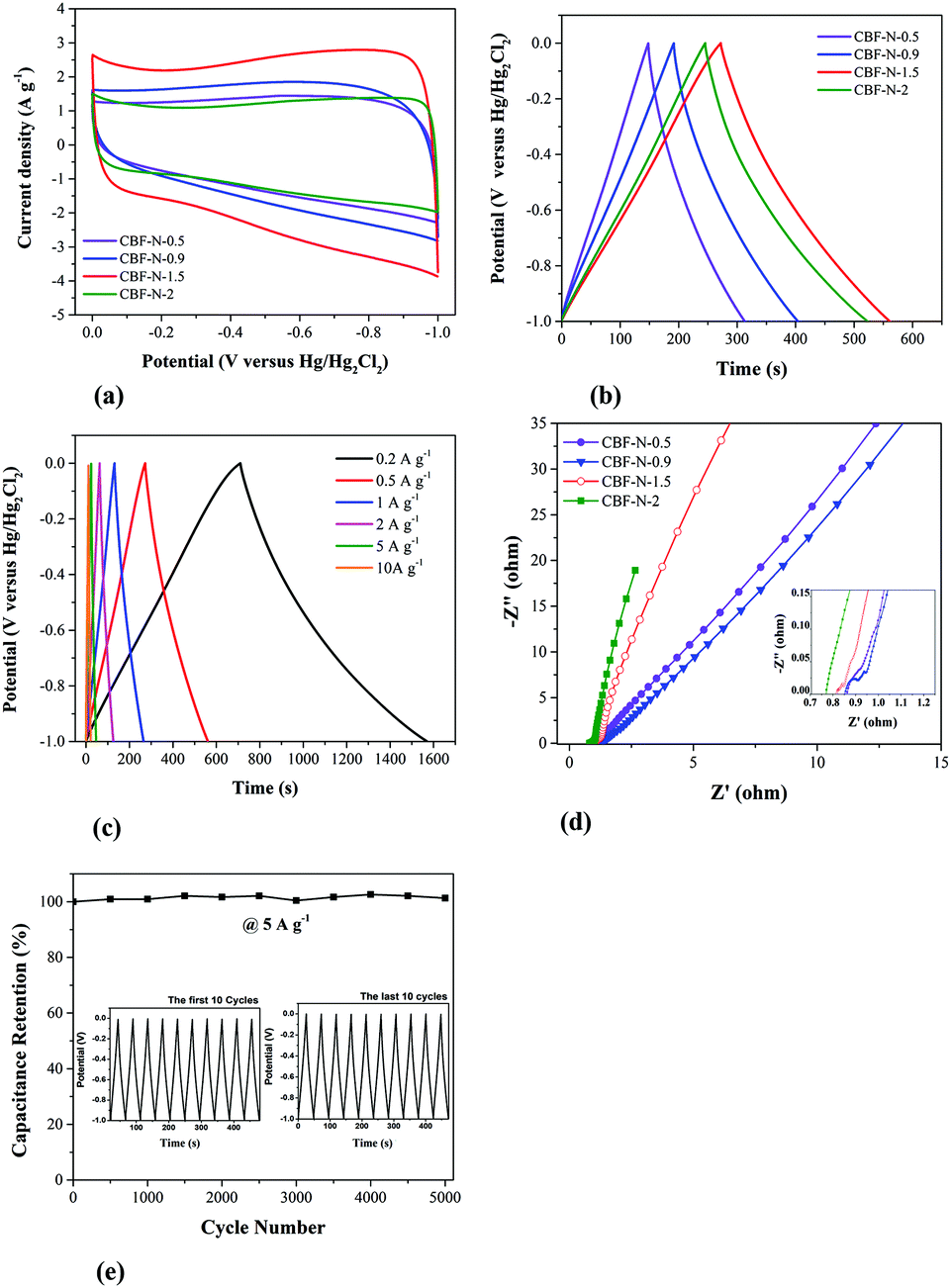 | ||
| Fig. 5 (a) CV curves of all samples at the scan rate of 20 mV s−1. (b) GCD curves of all samples at current density of 0.5 A g−1. (c) GCD curves of CBF–N-1.5 at different current densities. (d) Nyquist plots of all samples (inset is the amplification of Nyquist plots in the high frequency region). (e) Cycle life of CBF–N-1.5 at 5 A g−1 in 6 M KOH solution. | ||
The galvanostatic charge/discharge of CBF–N-1.5 at various current densities is shown in Fig. 5c. The curves were nearly symmetric, without an obvious IR drop, even at a high current load of 10 A g−1, suggesting that the supercapacitor electrode material possessed nearly ideal capacitive behavior and small internal resistance.32
Electrochemical impedance spectroscopy (EIS) is a powerful measurement that can be used to analyze and evaluate internal resistance between the electrode and electrolyte.33 The Nyquist plots of the CBF–N-x at open circuit potential are presented in Fig. 5d. For CBF–N-2, there is an almost-vertical line at the low frequency domain, indicating lower diffusion resistance (called the Warburg impedance in electrochemistry) of ions within the electrode.34 It was also found that CBF–N-2 possessed the lowest equivalent series resistance (ESR) compared to CBF–N-1.5 and other CBF–Nx. The ESR for the CBF–N-2 is 0.77 Ω, which is much lower in comparison with the CBF–N-1.5 (0.82 Ω), CBF–N-0.9 (0.85 Ω) and CBF–N-0.5 (0.86 Ω), indicating that the conductivity and charge transfer performance of CBF–N-x can be significantly enhanced through increasing the amount of dye on flocs. In general, the charge transfer resistance (RCT) values of the electrode can be described by the radius of semicircle arcs on the x-axis, and low values of RCT indicate smaller charge transfer resistance. Four small semicircles appeared at the high frequency zone. For comparison, the RCT of CBF–N-1.5 was clearly much lower (approximately 0.1 Ω), indicating that the charge transfer was fast. Towards practical applications of the CBF–N-x in supercapacitors, long cycling life is the most important parameter. The electrochemical stability of the CBF–N-1.5 electrode at a current density of 5 A g−1 for 5000 cycles is presented in Fig. 5e. Gravimetric capacitance remained at a high level in the three-electrode system (decreased less than 1% of the initial capacitance) after 5000 cycles, which indicated that the CBF–N-1.5 electrode displayed a long cycling life and electrochemical stability, suggesting it is a good electrode material for supercapacitors.
For industrial dye effluent treatment, the primary goal is to maintain color removal at the highest level possible. Thus, higher color removal efficiency from the flocculant and, at the same time, the synthesis of the nitrogen-doped materials originating from the flocs with good electrochemical performance, is not an easy task. Although this CBF–N-1.5 sample had good electrochemical properties, increasing the dosage of flocculant is not an ideal method to decrease dye flocculation capacity, because it lowers the color removal efficiency with flocculant overdosing. Fortunately, as a pH-responsive flocculant, the surface cationic degree and deprotonation behavior can be controlled by pH variation (ESI Fig. S5†). Therefore, we fixed the initial dye concentration (0.075 g L−1), increased the flocculant dosage from 0.0375 g L−1 (optimum concentration) to 0.049 g L−1 and increased the flocculation pH from 1.5 to 2.6. Using these flocculation conditions, the dye removal efficiency was 98.5%, and the flocculation capacity could be precisely controlled at 1.5 g g−1. This was because the amines were partially deprotonated at a higher pH, which reduced the available sorption sites in the chitosan chain and prevented restabilization of the particles in solution with flocculant overdose. The sludge floc (Q = 1.5 g g−1, R = 98.5%) used as a precursor was annealed in the same conditions to obtain CBF–N-1.5 (R = 98.5%). The supercapacitance performance of the CBF–N-1.5 (R = 98.5%) was further investigated to give CV and GCD curves (ESI Fig. S9†). The specific capacitance of the as-prepared electrode was 187 F g−1 at a current density of 0.2 A g−1, which was fairly close to that of the CBF–N-1.5 (R = 73.2%) electrode (172 F g−1). The high specific capacitance was mainly attributed to the appropriate dye flocculation capacity, which significantly improved the specific surface area and optimized the pore structure.
4. Conclusions
In this work, pH-responsive CBFs were synthesized and used as effective flocculants for a precise dye release control system. The results demonstrated that the dye uptake ratio was indeed tunable by a pH-controlled open/closed flocculant for dye release. The specific surface areas and pore structures of the resulting annealed products could be adjusted by varying the dye flocculation capacity. When the dye uptake reached 1.5 g g−1, the resulting N-doped carbon material demonstrated high electrochemical capacitance, 172 F g−1 at a current density of 0.2 A g−1, and good, long cycling stability with a capacity retention of 99% after 5000 cycles as the active material of a supercapacitor electrode. Taking full advantage of the pH-responsive characteristics of the flocculant, we easily tailored the color removal efficiency (>98%) in textile dyeing effluents, while maintaining the high energy storage capacity of supercapacitors. This work provides a new concept to balance environmental capacity and energy capacity using a smart pH-responsive flocculation system, which is a highly promising technology for the recycling of industrial wastewater to produce energy materials.Conflicts of interest
There are no conflicts to declare.Acknowledgements
The work was supported by National Natural Science Foundation of China (21467024, 51764049 and 21661027), Transformation of Technological Achievements in Shihezi University (CGZH201715) and the Project-sponsored by Scientific Research Start-up Fund for High-Level Talents, Shihezi University (KX0138).Notes and references
- L. Woeijye and A. F. Ismail, Desalination, 2009, 245, 321–348 CrossRef
.
- Z. Li, X. Zhang, J. Lin, S. Han and L. Lei, Bioresour. Technol., 2010, 101, 4440–4445 CrossRef CAS PubMed
- A. Sionkowska, Prog. Polym. Sci., 2011, 36, 1254–1276 CrossRef CAS
- K. A. S. Meraz, S. M. P. Vargas, J. T. L. Maldonado, J. M. C. Bravo, M. T. O. Guzman and E. A. L. Maldonado, Chem. Eng. J., 2016, 284, 536–542 CrossRef CAS
- M. Vakili, M. Rafatullah, B. Salamatinia, A. Z. Abdullah, M. H. Ibrahim, K. B. Tan, Z. Gholami and P. Amouzgar, Carbohydr. Polym., 2014, 113, 115–130 CrossRef CAS PubMed
- U. Habiba, T. A. Siddique, T. C. Joo, A. Salleh, B. C. Ang and A. M. Afifi, Carbohydr. Polym., 2017, 157, 1568–1576 CrossRef CAS PubMed
- R. Yang, H. Li, M. Huang, H. Yang and A. Li, Water Res., 2016, 95, 59–89 CrossRef CAS PubMed
- T. Lou, X. Wang, G. Song and G. Cui, Carbohydr. Polym., 2017, 170, 182–189 CrossRef CAS PubMed
- G. H. Yu, P. J. He and L. M. Shao, Bioresour. Technol., 2009, 100, 3193–3198 CrossRef CAS PubMed
- L. L. Zhang and X. S. Zhao, Chem. Soc. Rev., 2009, 38, 2520–2531 RSC
- M. Zhou, H. Li, K. Wang, S. Cheng and K. Jiang, Energy Environ. Sci., 2015, 8, 2916–2921 RSC
- J. Zhang and L. Dai, ACS Catal., 2015, 5, 7244–7253 CrossRef CAS
- K. Zhou, W. Zhou, X. Liu, Y. Wang, J. Wan and S. Chen, ACS Appl. Mater. Interfaces, 2014, 6, 14911–14918 CrossRef CAS PubMed
- E. Frackowiak, G. Lota, J. Machnikowski, C. Vix-Guterl and F. Béguin, Electrochim. Acta, 2006, 51, 2209–2214 CrossRef CAS
- J. Wei, D. Zhou, Z. Sun, Y. Deng, Y. Xia and D. Zhao, Adv. Funct. Mater., 2013, 23, 2322–2328 CrossRef CAS
- A. Baliani, G. J. Bueno, M. L. Stewart, V. Yardley, R. Brun, M. P. Barrett and I. H. Gilbert, J. Med. Chem., 2005, 48, 5570–5579 CrossRef CAS PubMed
- K. Zhang, Y. Shi, L. Wu, L. Chen, T. Wei, X. Jia, Z. Chen, M. Li, Y. Xu and Y. Wang, Carbohydr. Polym., 2018, 196, 209–216 CrossRef CAS PubMed
- L. Wu, X. Zhang, L. Chen, H. Zhang, C. Li, Y. Lv, Y. Xu, X. Jia, Y. Shi and X. Guo, RSC Adv., 2018, 8, 1274–1280 RSC
- Y. Wang, Y. Shi, M. Xu, L. Wu, X. Jia, T. Wei, S. Zhang and X. Guo, RSC Adv., 2016, 6, 44383–44391 RSC
- E. Guibal and J. Roussy, React. Funct. Polym., 2007, 67, 33–42 CrossRef CAS
- H. Jin-Yong, Y. Hyeonseok and J. Jyongsik, Small, 2010, 6, 679–686 CrossRef PubMed
- M. A. C. Stuart, W. T. S. Huck, J. Genzer, M. Müller, C. Ober, M. Stamm, G. B. Sukhorukov, I. Szleifer, V. V. Tsukruk and M. Urban, Nat. Mater., 2010, 9, 101–113 CrossRef PubMed
- Q. Liu, S. Zhang, D. Sun and J. Xu, Colloids Surf., A, 2010, 355, 151–157 CrossRef CAS
- F. Ulu, S. Barışçı, M. Kobya and M. Sillanpää, Chemosphere, 2015, 125, 108–114 CrossRef CAS PubMed
- X. Ma, L. Gan, M. Liu, P. Tripathi, Y. Zhao, Z. Xu, D. Zhu and L. Chen, J. Mater. Chem. A, 2014, 2, 8407–8415 RSC
- V. H. Nguyen and J.-J. Shim, Electrochim. Acta, 2015, 166, 302–309 CrossRef CAS
- D. Guo, R. Shibuya, C. Akiba, S. Saji, T. Kondo and J. Nakamura, Science, 2016, 351, 361–365 CrossRef CAS PubMed
- D. Hulicova-Jurcakova, M. Seredych, Q. L. Gao and T. J. Bandosz, Adv. Funct. Mater., 2010, 19, 438–447 CrossRef
- E. Y. L. Teo, L. Muniandy, E.-P. Ng, F. Adam, A. R. Mohamed, R. Jose and K. F. Chong, Electrochim. Acta, 2016, 192, 110–119 CrossRef CAS
- Z. Juan, Y. Chun-Peng, Y. Ya-Xia, W. Li-Jun and G. Yu-Guo, Adv. Mater., 2016, 28, 9539–9544 CrossRef PubMed
- P. Bairi, R. G. Shrestha, J. P. Hill, T. Nishimura, K. Ariga and L. K. Shrestha, J. Mater. Chem. A, 2016, 4, 13899–13906 RSC
- C. Chen, Y. Zhang, Y. Li, J. Dai, J. Song, Y. Yao, Y. Gong, I. Kierzewski, J. Xie and L. Hu, Energy Environ. Sci., 2017, 10, 538–545 RSC
- D. Andre, M. Meiler, K. Steiner, C. Wimmer, T. Soczka-Guth and D. U. Sauer, J. Power Sources, 2011, 196, 5349–5356 CrossRef CAS
- B. Xu, S. Hou, G. Cao, F. Wu and Y. Yang, J. Mater. Chem., 2012, 22, 19088–19093 RSC
Footnote |
| † Electronic supplementary information (ESI) available. See DOI: 10.1039/c8ra07424k |
| This journal is © The Royal Society of Chemistry 2018 |