 Open Access Article
Enhanced dielectric properties of colossal permittivity co-doped TiO2/polymer composite films
Mei-Yan Tsea,
Xianhua Wei *b,
Chi-Man Wonga,
Long-Biao Huanga,
Kwok-ho Lam
 c,
Jiyan Daia and
Jianhua Hao
 *ad
*ad
aDepartment of Applied Physics, The Hong Kong Polytechnic University, Hung Hom, Hong Kong, P. R. China. E-mail: jh.hao@polyu.edu.hk
bState Key Laboratory of Environment-friendly Energy Materials, Southwest University of Science and Technology, Mianyang 621010, P. R. China. E-mail: weixianhua@swust.edu.cn
cDepartment of Electrical Engineering, The Hong Kong Polytechnic University, Hung Hom, Hong Kong, P. R. China
dThe Hong Kong Polytechnic University Shenzhen Research Institute, Shenzhen 518057, P. R. China
First published on 24th September 2018
Abstract
Colossal permittivity (CP) materials have shown great technological potential for advanced microelectronics and high-energy-density storage applications. However, developing high performance CP materials has been met with limited success because of low breakdown electric field and large dielectric loss. Here, composite films have been developed based on surface hydroxylated ceramic fillers, (Er + Nb) co-doped TiO2 embedded in poly(vinylidene fluoride trifluoroethylene) matrix by a simple technique. We report on simultaneously observing a large dielectric constant up to 300, exceptional low dielectric loss down to 0.04 in the low frequency range, and an acceptable breakdown electric field of 813 kV cm−1 in the composites. Consequently, this work may pave the way for developing highly stable and superior dielectrics through a simple and scalable route to meet requirements of further miniaturization in microelectronic and energy-storage devices.
1. Introduction
Colossal permittivity (CP) materials have received considerable attention because they can be used as super dielectrics in the fields of microelectronics and energy storage. Several emergent CP materials have also been proposed, such as CaCu3Ti4O12 (CCTO),1 doped NiO,2 and La2−xSrxNiO4 (ref. 3) in the past decade. However, these classes of materials are not ideal for straightforward applications due to high dielectric loss. In addition, the permittivity and loss are found to increase or decrease in tandem. Therefore, the exploration of alternative CP materials with low loss has attracted increasing attention. Noted that CP (εr > 104) and low loss (mostly < 0.05) were found in (In + Nb) co-doped rutile TiO2 ceramic bulks by Liu's group.4 The dielectric properties are almost independent over a wide frequency and temperature range, which is superior to other earlier CP materials including ferroelectric oxides. Another merit of employing the host in the CP system benefits from environment-friendly, non-toxic and abundant of TiO2 used.Until now, CP phenomena with similar dielectric properties have also been confirmed in a serial of rutile TiO2 ceramics by co-doping other acceptor or isovalent impurities and donor ions.5–17 Unfortunately, very low breakdown strength values below 1 kV cm−1 have been found, which would inhibit the further application of the new discovered CP materials.18–22 Recently, the breakdown electric field was enhanced to 5.77 kV cm−1 in (In0.5Nb0.5)0.005(Ti1−xZrx)0.995O2 through reducing grain size and introducing secondary insulating phase.23 Although the breakdown electric field was still small, it suggests that making the composites of CP and other insulating phase like polymer is an effective to improve the breakdown strength.
A great deal of effort has been put to explore on making ceramic/polymer dielectric composites to overcome the low dielectric constants of polymers or low breakdown field of ceramics.24–26 However, limited success has been achieved in the composites of emergent CP/polymer. For example, although CCTO/poly(vinylidene fluoride trifluoroethylene) (P(VDF-TrFE)) exhibited a large dielectric constant (610), it displayed a relatively high loss (>0.1).27 Recently, the stored energy density of 8.46 J cm−3 was obtained at a large electric field of 3400 kV cm−1 for CCTO@Al2O3 nanofibers/PVDF nanocomposites. But the dielectric permittivity of the composites dropped below 20.28 In addition, a very large dielectric permittivity above 104 has been observed in TiO2/conducting polymer composites due to interfacial polarization.29 Thus, it is anticipated that the development of the CP TiO2/polymer composites might further light on the practical application since excellent dielectric properties have been found in the CP ceramics co-doped by different metal-ions in our studies.8,9,13,14 Moreover, the additional flexibility feature of the composites would also possess broad application prospects in portable and wearable electronics. But there is no report on the above aspects with TiO2-based CP materials.
It is well-known that the huge dielectric difference between ceramic fillers and polymer matrix would weaken the breakdown strength of the composites due to inhomogeneous electric field distribution. Agglomeration and phase separation from the matrix might deteriorate the electrical performance of the composites. Consequently, surface modification is highly desirable for improving compatibility in ceramic/polymer composites. Here, we report ceramic/polymer composite films by combining solution casting and hot-pressing (HP) processes. Solution casting offers opportunity for high reliability and low cost manufacturing, while HP method reduces voids and other structural defects in composites. The poly(vinylidene fluoride trifluoroethylene) (P(VDF-TrFE)) 55/45 mol% copolymer was utilized as matrix. It has a very weak piezoelectric effect and high dielectric constant (∼15) at room temperature due to the high polarity from fluorine with high electronegativity. (Er + Nb)-modified TiO2 was used as ceramic fillers. Furthermore, it is recognized that the fluorine atoms present in the polymer strongly interact with Ti4+ ions through dipole–dipole interaction. The surface of ceramic fillers was chemically modified by H2O2 to introduce hydroxyl groups. Finally, high-performance of dielectric capacitors simultaneously possessing large dielectric constant, negligible dielectric loss and acceptable breakdown electric field is successfully achieved in the flexible composites.
2. Methods/experimental
Ceramic/polymer composite samples were fabricated by combining solution casting and HP method, as shown in the schematic illustration in Fig. 1. The ceramic powders (Er0.5Nb0.5)xTi1−xO2 (x (Er + Nb), x = 2.5%) can be found in our previous reports.9 The sintered ceramic powders were dispersed in an aqueous solution of hydrogen peroxide (H2O2, 35% w/v, Acros Organics) with stirring and heating at 100 °C for 3 h. The suspensions were subsequently centrifuged at 3000 rpm for 5 min. The collected powders were washed with distilled water and ethanol. Finally, surface hydroxylated ceramic powders (2.5% (Er + Nb)–OH) were obtained by drying overnight at 70 °C in an oven. P(VDF-TrFE) 55/45 mol% copolymer powders purchased from Piezotech were utilized as the matrix. To begin with, P(VDF-TrFE) copolymer powders were dissolved in a dimethylformamide (DMF) without further purification to obtain a solution with 10 wt% concentration. Different weight ratios of 2.5% (Er + Nb)–OH were ultrasonically dispersed in DMF and then introduced into P(VDF-TrFE) solution with constantly stirring at 50 °C for 8 h and sonicated for about 30 min to form stable suspensions. As-deposited composite film was subsequently dried on a hotplate at 70 °C. The film was annealed at 120 °C overnight in an oven and then allowed to cool to room temperature. To improve the uniformity, the solution-cast film was then hot-pressed at 200 °C for 10 min. Gold layers were deposited on the films by sputtering to serve as electrode layers for electrical measurements.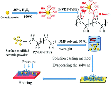 | ||
| Fig. 1 Schematic illustration of the hydroxylation of ceramic powders, formation of hydrogen bond and fabrication of ceramic/polymer composite. | ||
X-ray Diffraction (XRD, Smart Lab; Rigaku Co., Japan), the Bruker Vertex-70 Fourier transform infrared (FTIR) spectrophotometer, field emission scanning electron microscopy (FESEM) were used for material morphology and crystal structure characterization. An impedance analyzer (HP 4294A; Agilent Technologies Inc., Palo Alto, CA) was used to measure the frequency dependence of the dielectric properties over the range of 102 to 105 Hz at room temperature. A high voltage power supply (model P0621, TREK, Inc.) was used for the breakdown strength measurement. All samples were kept inside a 400 mL beaker filled with silicon oil to limit moisture influence on testing results and sparking while applying high voltage.
3. Results and discussion
XRD patterns of various samples are presented in the 2θ range from 10° to 75° (Fig. 2). As-synthesized P(VDF-TrFE) film showed broad peak centered at around 2θ = 19°. This indicates the co-existence of crystalline non-polar α and polar β phases of the P(VDF-TrFE) copolymer, corresponding to the orientation planes of (020) at 18.7° and (110) at 19.2°, respectively.30 The intensities of copolymer peaks for two hot-pressed composites were suppressed by strong peaks of ceramic structure. Similar to the previous work, the inorganic component exhibited an increased lattice strain.9 A small amount of secondary phase of Er2Ti2O7 was found in the composites. It is worth emphasizing that the rutile TiO2 phase remained unchanged in the composites for both untreated and surface modified 2.5% (Er + Nb) ceramic fillers.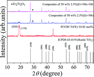 | ||
| Fig. 2 XRD patterns of the as-synthesized P(VDF-TrFE) film, hot-pressed composite samples doped with 50 wt% of untreated and surface modified 2.5% (Er + Nb) ceramic fillers. | ||
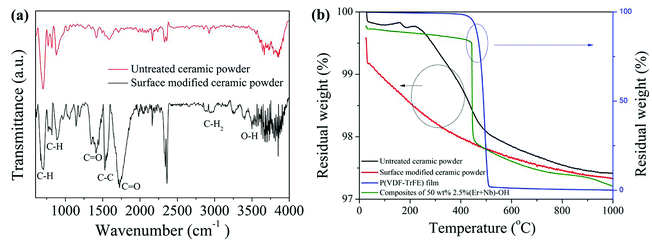
Fourier transform infrared (FTIR) spectra in the ATR mode of the untreated and surface modified ceramic powders are shown in Fig. 3(a), ranging from 600 to 4000 cm−1. Absorption band of OH groups at around 3400 cm−1 confirms the surface modification of ceramic powders, attributed to O–H stretching.31 This result indicates that hydroxyl was introduced onto the surface of ceramic powders after treatment with H2O2. The peaks at 690–900 cm−1, 1440/1700 cm−1, and 1528 cm−1 are assigned to aromatic CH, C![[double bond, length as m-dash]](https://www.rsc.org/images/entities/char_e001.gif) O stretching, and C–C in-plane vibration of the copolymer, respectively. It is noticed that all intensity of vibrational stretching corresponding to the surface modified ceramic powders was enhanced. Fig. 3(b) provides another evidence of the presence of the hydroxyl groups. There was a difference in the weight loss between the untreated and surface modified ceramic powders. The weight loss of the (Er + Nb)–OH was larger than that of the untreated one, which could be attributed to the vaporization of the hydroxyl groups. The finding implies that the hydroxyl groups were successfully introduced into the surface of the ceramic powders as a relatively large weight loss was observed before 300 °C. It is seen that both weight of P(VDF-TrFE) film and composite film with 50 wt% 2.5% (Er + Nb)–OH ceramic fillers were relatively stable below 450 °C. However, there was an obvious weight loss and decomposition for the copolymer at around 500 °C, whereas composite exhibited better stability behaviors, owing to the presence of ceramics fillers in copolymer matrix.
O stretching, and C–C in-plane vibration of the copolymer, respectively. It is noticed that all intensity of vibrational stretching corresponding to the surface modified ceramic powders was enhanced. Fig. 3(b) provides another evidence of the presence of the hydroxyl groups. There was a difference in the weight loss between the untreated and surface modified ceramic powders. The weight loss of the (Er + Nb)–OH was larger than that of the untreated one, which could be attributed to the vaporization of the hydroxyl groups. The finding implies that the hydroxyl groups were successfully introduced into the surface of the ceramic powders as a relatively large weight loss was observed before 300 °C. It is seen that both weight of P(VDF-TrFE) film and composite film with 50 wt% 2.5% (Er + Nb)–OH ceramic fillers were relatively stable below 450 °C. However, there was an obvious weight loss and decomposition for the copolymer at around 500 °C, whereas composite exhibited better stability behaviors, owing to the presence of ceramics fillers in copolymer matrix.
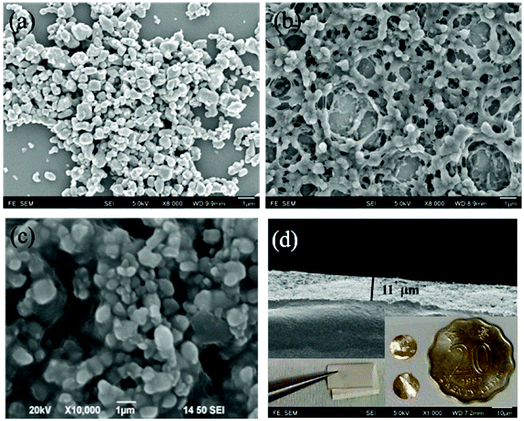
A spherical morphology is shown in the ceramic powders, with an average size of about 1 μm (Fig. 4(a)). Field emission scanning electron microscopy (FESEM) was used to investigate the possible origin in respect of microstructure and surface morphology of the specimens. By comparing Fig. 4(b) and (c), composite of (Er + Nb)–OH shows a better combination with P(VDF-TrFE) than the untreated one, which is similar to the previous report.32 This result illustrates the surface hydroxylation not only facilitates uniform dispersion of ceramic particles in the polymer matrix, but also benefits for forming strong interfacial adhesion with the polymer matrix. More importantly, surface modification could promote the accumulation of charge carriers at interface, offer stronger interfacial polarization, and enlarge the mean electric field acting on ceramic particles. Composites were hot pressed for improving the uniformity and avoiding the pinholes. Fig. 4(d) shows that the HP fabricated composite film containing 50 wt% 2.5% (Er + Nb)–OH ceramic fillers had a good uniformity and dense structure. The thickness of the sample is 11 μm. The inset is a photograph of the flexible composite film and it is coated by sputtered golden electrode. The untreated composite was also prepared under identical procedure for comparison.
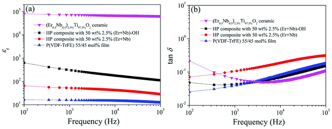
εr of composite is between that of ceramic (εr ∼ 104) and pure copolymer (εr ∼ 16). An excellent dielectric property was achieved in the HP composite filled with 50 wt% 2.5% (Er + Nb)–OH ceramic fillers, where εr and tan![[thin space (1/6-em)]](https://www.rsc.org/images/entities/char_2009.gif) δ were measured to be 300 and 0.04 at 1 kHz, respectively (Fig. 5). The composite films consist of co-doped TiO2 ceramic powders, copolymer and interfacial region. This observed permittivity (∼300) should be ascribed to the contribution of both surface polarization (interface region) and the individual components (co-doped TiO2 ceramics). It is found that intrinsic (electron-pinned defect-dipole) and extrinsic mechanisms are responsible for the observed high-performance CP in co-doped TiO2 ceramics.9 The induced defect dipole clusters generate CP and low tan
δ were measured to be 300 and 0.04 at 1 kHz, respectively (Fig. 5). The composite films consist of co-doped TiO2 ceramic powders, copolymer and interfacial region. This observed permittivity (∼300) should be ascribed to the contribution of both surface polarization (interface region) and the individual components (co-doped TiO2 ceramics). It is found that intrinsic (electron-pinned defect-dipole) and extrinsic mechanisms are responsible for the observed high-performance CP in co-doped TiO2 ceramics.9 The induced defect dipole clusters generate CP and low tan![[thin space (1/6-em)]](https://www.rsc.org/images/entities/char_2009.gif) δ in co-doped TiO2 ceramics, where Nb5+ ions act as substitution donor, creating the delocalized electrons from partial reduction of Ti4+ to Ti3+, while Er3+ ions restrict the electron drift in the lattice hopping. The dielectric response of interfacial region might be due to the process of surface modification, leading to stronger interfacial polarization. As expected, the εr of the surface modified composite was significantly higher than the untreated one. For example, at the same frequency, the εr of untreated composite only reached about 52. Furthermore, the tan
δ in co-doped TiO2 ceramics, where Nb5+ ions act as substitution donor, creating the delocalized electrons from partial reduction of Ti4+ to Ti3+, while Er3+ ions restrict the electron drift in the lattice hopping. The dielectric response of interfacial region might be due to the process of surface modification, leading to stronger interfacial polarization. As expected, the εr of the surface modified composite was significantly higher than the untreated one. For example, at the same frequency, the εr of untreated composite only reached about 52. Furthermore, the tan![[thin space (1/6-em)]](https://www.rsc.org/images/entities/char_2009.gif) δ was reduced significantly over all frequencies through modifying the surface of ceramic powders in the composites. The results illustrate that both satisfactory εr and low tan
δ was reduced significantly over all frequencies through modifying the surface of ceramic powders in the composites. The results illustrate that both satisfactory εr and low tan![[thin space (1/6-em)]](https://www.rsc.org/images/entities/char_2009.gif) δ are accomplished in the homogeneous film.
δ are accomplished in the homogeneous film.
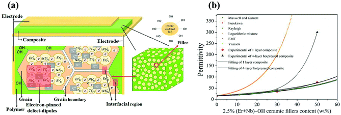
Such large dielectric constants in the ceramic/polymer composites were previously described by some effective medium theory. Fig. 6(a) schematically illustrates the capacitor of surface modified (Er + Nb) co-doped TiO2/P(VDF-TrFE) composite. Spherical hydroxylated (Er + Nb) co-doped TiO2 ceramic fillers were dispersed homogeneously in P(VDF-TrFE) matrix. It was reported that CP as well as low loss in dielectric materials are the consequence of the formation of defect-dipole complex. The effective dielectric constants (εeff) of HP surface modified composites are depicted in Fig. 6(b). The model of logarithmic mixture rule was ineffective as the predicted εeff deviated from the experimental value for all the composites. However, theoretical εeff values were comparable to the experimental results by using Maxwell and Garnett, Furukawa and Rayleigh's models. The difference between the experimental data and the predicted value was less than 5%. It is reported that Maxwell and Garnett, Furukawa et al., and Rayleigh models based on spherical fillers randomly immersed at the polymeric matrix, which were fitted well with experimental values.32 The EMT model is similar to the Maxwell–Garnett model, in which fillers particles are homogenously distributed, non-interacting and roughly spherical surrounded by a concentric matrix layer:
 | (1) |
 | (2) |
In this work, our experimental values are in close agreement with the Yamada model by taking into account the shape factor. The n value is found to be 3.6 as obtained from the best fit result. It was claimed that an n value of 3.5 was applicable to PZT with the particle size of 1.5 μm reported by Gregorio et al.,34 which is consistent with 1 μm of the ceramic fillers in this work. However, the experimental εr of 4-layer HP composites under higher concentration of surface modified ceramic fillers deviates from all models. The possible reason is that interfacial physical and chemical properties of composites have not been taken into account in the models based on effective medium theory which was denoted in Fig. 6(a). Thus, the interfacial effect of the composite needs to be further studied in detail. It should be concluded that εeff of composite material is not only dependent on εr of the polymer and the fillers, size and shape of the fillers and the volume fraction of the fillers, but also on the interphase region and layers under the influence of HP.35 These aspects are essential to be considered for fabricating composites with improved dielectric properties.
Fig. 7 shows the breakdown strength of the same composition composite films followed the two-parameter Weibull distribution:
| P(E) = 1 − e−(E/E0)β | (3) |
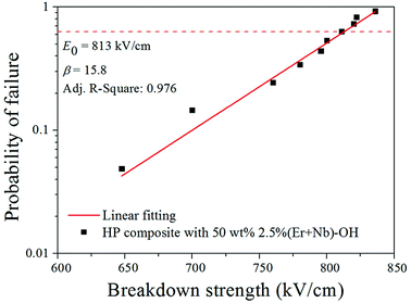 | ||
| Fig. 7 Failure probability of dielectric breakdown deduced from Weibull distribution for composite films with 50 wt% 2.5% (Er + Nb)–OH ceramic fillers. | ||
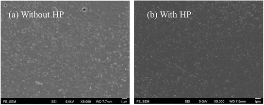 | ||
| Fig. 8 FESEM images of the surface morphology of composite film with 50 wt% 2.5% (Er + Nb)–OH ceramic fillers, (a) without HP and (b) HP samples. | ||
There are many reports to balance the dielectric permittivity and breakdown strength in various dielectric composites.37–39 Ferroelectric ceramics fillers exhibit higher breakdown strengths, but generally have lower dielectric constants than our sample. In recent years, many studies have focused on the introduction of controllable morphology nanofillers, for achieving great enhancements in both polarization and breakdown strength.40,41 Nevertheless, the fabrication processes for those nanostructures are usually complicated, and the production capacity might not suitable for mass production-scale. Apparently, the process developed in this work is relatively simple, low cost and mass production for the composite since the ceramic powders are fabricated by conventional solid-state sintering method. It should be pointed that there is not any reported simultaneous observation of large dielectric constant, low loss and acceptable breakdown strength based on emergent lead-free CP material. It is believed that the approach of this study can be extended to other types of dielectric composites.
4. Conclusion
In summary, we report the simultaneous observation of robust large dielectric constant, very low loss and acceptable breakdown strength in the flexible CP based composites. The composites composed of P(VDF-TrFE) and surface functionalized (Er, Nb) TiO2 ceramic fillers with homogeneous ceramic particle dispersions were prepared by practical solution-cast and hot-pressing method. We found that the surface hydroxylation of ceramic fillers benefits dielectric properties, breakdown strength of the composites. The results are helpful for not only investigating the fundamental dielectric properties of the composite materials, but also developing device applications in advanced microelectronics and high-density energy storage systems.Conflicts of interest
There are no conflicts to declare.Acknowledgements
J. H. acknowledges financial support from the grant Research Grants Council of Hong Kong (GRF No. PolyU 153004/14P) and National Natural Science Foundation of China (No. 11474241). X. H. acknowledges financial support from the Program for Young Science and Technology Innovation Team of Sichuan Province (2017TD0020).References
- M. A. Subramanian, D. Li, N. Duan, B. A. Reisner and A. W. Sleight, J. Solid State Chem., 2000, 151, 323 CrossRef.
- J. B. Wu, C. W. Nan, Y. H. Lin and Y. Deng, Phys. Rev. Lett., 2002, 89, 217601 CrossRef PubMed.
- S. Krohns, P. Lunkenheimer, Ch. Kant, A. V. Pronin, H. B. Brom, A. A. Nugroho, M. Diantoro and A. Loidl, Appl. Phys. Lett., 2009, 94, 122903 CrossRef.
- W. B. Hu, Y. Liu, R. L. Withers, T. J. Frankcombe, L. Norén, A. Snashall, M. Kitchin, P. Smith, B. Gong, H. Chen, J. Schiemer, F. Brink and J. Wong-Leung, Nat. Mater., 2013, 12, 821 CrossRef PubMed.
- X. J. Cheng, Z. W. Li and J. G. Wu, J. Mater. Chem. A, 2015, 3, 5805 RSC.
- W. Dong, W. B. Hu, A. Berlie, K. Lau, H. Chen, R. L. Withers and Y. Liu, ACS Appl. Mater. Interfaces, 2015, 7, 25321 CrossRef PubMed.
- W. B. Hu, K. Lau, Y. Liu, R. L. Withers, H. Chen, L. Fu, B. Gong and W. Hutchison, Chem. Mater., 2015, 27, 4934 CrossRef.
- X. H. Wei, W. J. Jie, Z. B. Yang, F. G. Zheng, H. Z. Zeng, Y. Liu and J. H. Hao, J. Mater. Chem. C, 2015, 3, 11005 RSC.
- M. Y. Tse, X. H. Wei and J. H. Hao, Phys. Chem. Chem. Phys., 2016, 18, 24270 RSC.
- Z. W. Li, J. G. Wu, D. Q. Xiao, J. G. Zhu and W. J. Wu, Acta Mater., 2016, 103, 243 CrossRef.
- Z. W. Li, J. G. Wu and W. J. Wu, J. Mater. Chem. C, 2015, 3, 9206 RSC.
- W. Tuichai, P. Srepusharawoot, E. Swatsitang, S. Danwittayakuld and P. Thongbai, Microelectron. Eng., 2015, 146, 32 CrossRef.
- C. Yang, M. Y. Tse, X. H. Wei and J. H. Hao, J. Mater. Chem. C, 2017, 5, 5170 RSC.
- C. Yang, X. H. Wei and J. H. Hao, J. Am. Ceram. Soc., 2018, 101, 307 CrossRef.
- W. Tuichai, S. Danwittayakul, N. Chanlek, P. Thongbai and S. Maensiri, J. Alloys Compd., 2017, 703, 139 CrossRef.
- W. Dong, W. B. Hu, T. Frankcombe, D. H. Chen, C. Zhou, Z. X. Fu, L. Cândido, G. Q. Hai, H. Chen, Y. X. Li, R. Withers and Y. Liu, J. Mater. Chem. A, 2017, 5, 5436 RSC.
- Y. Yu, W. L. Li, Y. Zhao, T. D. Zhang, R. X. Song, Y. L. Zhang, Z. Y. Wang and W. D. Fei, J. Eur. Ceram. Soc., 2018, 38, 1576 CrossRef.
- J. Li, F. Li, Y. Zhuang, L. Jin, L. Wang, X. Wei, Z. Xu and S. Zhang, J. Appl. Phys., 2014, 116, 074105 CrossRef.
- Y. Q. Wu, X. Zhao, J. L. Zhang, W. B. Su and J. Liu, Appl. Phys. Lett., 2015, 107, 242904 CrossRef.
- Y. Song, P. Liu, X. Zhao, B. Guo and X. Cui, J. Alloys Compd., 2017, 722, 676 CrossRef.
- T. Nachaithong, W. Tuichai, P. Kidkhunthod, N. Chanlek, P. Thongbai and S. Maensiri, J. Eur. Ceram. Soc., 2017, 37, 3521 CrossRef.
- G. Liu, H. Fan, J. Xu, Z. Liu and Y. Zhao, RSC Adv., 2016, 6, 48708 RSC.
- B. Guo, P. Liu, X. Cui and Y. Song, J. Alloys Compd., 2018, 740, 1108 CrossRef.
- Y. Wang, J. Cui, Q. Yuan, Y. Niu, Y. Bai and H. Wang, Adv. Mater., 2015, 27, 6658 CrossRef PubMed.
- Q. Chi, T. Ma, Y. Zhang, Y. Cui, C. Zhang, J. Lin, X. Wang and Q. Lei, J. Mater. Chem. A, 2017, 5, 16757 RSC.
- X. Zhang, Y. Shen, Q. Zhang, L. Gu, Y. Hu, J. Du, Y. Lin and C. W. Nan, Adv. Mater., 2015, 27, 819 CrossRef PubMed.
- M. Arbatti, X. Shan and Z.-Y. Cheng, Adv. Mater., 2007, 19, 1369 CrossRef.
- Q. Chi, X. Wang, C. Zhang, Q. Chen, M. Chen, T. Zhang, L. Gao, Y. Zhang, Y. Cui, X. Wang and Q. Lei, ACS Sustainable Chem. Eng., 2018, 6, 8641 CrossRef.
- A. Dey, S. De, A. De and S. K. De, J. Nanosci. Nanotechnol., 2006, 6, 1427 CrossRef PubMed.
- G. T. Davis, T. Furukawa, A. Lovinger and M. G. Broadhurst, Macromolecules, 1982, 15, 329 CrossRef.
- Z. Pi, J. Zhang, C. Wen, Z. Zhang and D. Wu, Nano Energy, 2014, 7, 33 CrossRef.
- T. Furukawa, K. Ishida and E. Fukada, J. Appl. Phys., 1979, 50, 4904 CrossRef.
- T. Yamada, T. Ueda and T. Kitayama, J. Appl. Phys., 1982, 53, 4328 CrossRef.
- R. Gregorio Jr, M. Cestari and F. E. Bernardino, J. Mater. Sci., 1996, 31, 2925 CrossRef.
- M. G. Todd and F. G. Shi, J. Appl. Phys., 2003, 94, 4551 CrossRef.
- D. Zhang, W. Liu, L. Tang, K. Zhou and H. Luo, Appl. Phys. Lett., 2017, 110, 133902 CrossRef.
- Y. Bai, Z. Y. Cheng, V. Bharti, H. S. Xu and Q. M. Zhang, Appl. Phys. Lett., 2000, 76, 3804 CrossRef.
- S. Liu, S. Xiu, B. Shen, J. Zhai and L. B. Kong, Polymers, 2016, 8, 45 CrossRef.
- S. Adireddy, V. S. Puli, T. J. Lou and D. B. Chrisey, J. Sol-Gel Sci. Technol., 2015, 73, 641 CrossRef.
- X. Zhang, Y. Shen, Q. Zhang, L. Gu, Y. Hu, J. Du, Y. Lin and C. W. Nan, Adv. Mater., 2015, 27, 819 CrossRef PubMed.
- L. Xie, X. Huang, B. W. Li, C. Zhi, T. Tanaka and P. Jiang, Phys. Chem. Chem. Phys., 2013, 15, 17560 RSC.
| This journal is © The Royal Society of Chemistry 2018 |

