 Open Access Article
Self-standing cellulose nanofiber/poly(3,4-ethylenedioxythiophene):poly(4-styrenesulfonate)/ionic liquid actuators with superior performance†
Naohiro Terasawa * and
Kinji Asaka
Inorganic Functional Material Research Institute, National Institute of Advanced Industrial Science and Technology (AIST), 1-8-31 Midorigaoka, Ikeda, Osaka 563-8577, Japan. E-mail: terasawa-naohiro@aist.go.jp
First published on 25th September 2018
Abstract
This paper describes new actuators with cellulose nanofiber/poly(3,4-ethylenedioxythiophene):poly(4-styrenesulfonate)/ionic liquid (CNF/PEDOT:PSS/IL) structures. Devices containing these structures exhibit higher strain and maximum generated stress than those based on only PEDOT:PSS/IL. The new actuator system contains an electrode, which is an electrochemical capacitor, and which consists of both a faradaic capacitor (FC) and a small electric double-layer capacitor (EDLC), i.e., PEDOT:PSS. This combined capacitor plays the role of an FC and a base polymer, and the CNF skeleton is used in the place of carbon nanotubes (CNTs). This device therefore functions differently from traditional CNT/PVdF–HFP/IL actuators, which are only used as EDLC units and from PEDOT:PSS/vapor-grown carbon nanofibers (VGCF)/IL actuators, which are used as hybrid (FC and EDLC) units. The developed films are novel, robust, and flexible, and demonstrate potential as actuator materials for wearable energy-conversion devices. A double-layer charging kinetic model, which is similar to that previously proposed for PEDOT:PSS/CNT/IL actuators, is developed to explain the oxidation and reduction of PEDOT:PSS. This model successfully simulates the frequency-dependent displacement response of actuators.
Introduction
Fundamental research into bionanofibers and their applications is gaining importance because of growing environmental concerns as well as the drive to create sustainable societies based on recycling.1 Cellulose, which is a crystalline polysaccharide, is the most abundant biopolymer and is mainly obtained from wood pulp. Cellulose exhibits a unique hierarchical structure comprising linear glucan chains → 3–4 nm wide crystalline cellulose microfibrils comprising 30–40 cellulose chains → microfibril bundles → cell walls → fibers → plant tissue → trees or other plants, which comprise hemicellulose and lignin to reinforce living plants. For decades, human beings have been using chemically and mechanically modified cellulose, in addition to original cellulose fibers, in various fields, ranging from commodities such as paper and textiles to high-tech materials, such as hollow fibers for artificial kidney dialysis; flat-panel components in liquid crystal displays; food additives; and medicinal components. Therefore, cellulose nanofibers (CNFs) are expected to replace carbon nanofibers in the networks of open mesopores formed in electrodes by highly entangled CNFs.Conductive polymers (CPs), another component of actuator systems, are highly appropriate for use in electrochemical capacitors as a result of their affordability, highly conductive doped states, negligible environmental impact, wide voltage windows, porosity, large storage capacity, redox activities that are adjustable by chemical modification, and reversibility.2–6
In this regard, a polythiophene derivative, poly(3,4-ethylenedioxythiophene) (PEDOT), is considered the most useful CP known to date because of its electrical conductivity, stability, and processability.7 Thus, it is produced commercially and is applied in a wide range of electronic components, including solid electrolytic capacitors, antistatic coatings, light-emitting diodes, organic field-effect transistors, and organic solar cells.7 PEDOT, which has been modified by doping with poly(4-styrenesulfonate) (PEDOT:PSS), is an important type of CP because of its ability to form colloidal particulate dispersions in water. Moreover, its mechanical properties are superior, and it exhibits tunable conductivity (0.1–3000 S cm−1) and thermal stability.8,9 PEDOT:PSS has therefore been employed in several organic and polymeric electronic/optical devices.10–13 PEDOT:PSS-based electrodes have been examined14–16 and confirmed capable of converting electrical to mechanical energy.17,18
Lately, soft materials with the ability to generate mechanical energy from electrical energy have been extensively investigated. These materials have found use in many applications, such as robotics, prosthetics, tactile and optical displays, microelectromechanical systems, and medical devices.19 In these applications, actuators based on low-voltage electroactive-polymers (EAPs) characterized by their fast response are particularly useful because it is possible to use them as artificial muscle-like actuators in biomedical and human affinity applications.20,21 Previously, our group22–24 reported the fabrication of the first dry actuator using a “bucky gel”,25 which comprised gelatinous ionic liquid (IL)-containing single-walled carbon nanotubes (SWCNTs) at room temperature. The gel exhibits a bimorph configuration, wherein a layer of IL electrolyte supported on a layer of polymer was inserted between two electrode layers consisting of polymer-supported bucky-gel. The design enables rapid device operation and extends the lifespan of the device in air at a low applied voltage. Moreover, because these ILs have an intrinsically low volatility, wide potential window, and high ionic conductivity, they can be used in rapid response actuators as well as devices demanding high electrochemical stability.26 In addition, the electrochemical and electromechanical properties of these actuators depend on the particular IL, polymeric materials, and nanocarbon employed.24,27–30
This study entailed the development of novel CNT-free, hybrid, and self-standing actuators (CNF/PEDOT:PSS/IL). These actuator devices (mainly using faradaic capacitors (FCs)) exhibited superior strain performance (Fig. 1).
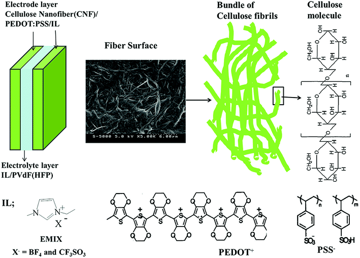 | ||
| Fig. 1 Configuration of the CNF/PEDOT:PSS/IL electrode actuator and the molecular structures of its constituent ILs and polymers. | ||
Experimental
Materials
CNFs prepared by the aqueous counter collision method, hardwood bleached kraft pulp (LB) (ca. 10 wt%), and bamboo bleached kraft pulp (BB) (ca. 10 wt%) were used as received from Chuetsu Pulp & Paper Co., Ltd. PEDOT:PSS (polyion complex; 1![[thin space (1/6-em)]](https://www.rsc.org/images/entities/char_2009.gif) :
:![[thin space (1/6-em)]](https://www.rsc.org/images/entities/char_2009.gif)
![[thin space (1/6-em)]](https://www.rsc.org/images/entities/char_2009.gif) 2.5 w/w) was purchased from Aldrich (number 768618). The ILs were 1-ethyl-3-methylimidazolium tetrafluoroborate (EMI[BF4]; Kanto Chemical Co., Inc.) and 1-ethyl-3-methylimidazolium triflate (EMI[CF3SO3]; Kanto Chemical Co., Inc.), and these were used as received. Their chemical structures are schematically illustrated in Fig. 1. Other reagents included poly(vinylidene fluoride-co-hexafluoropropylene) (PVdF–HFP), Kynar Flex 2801 (Arkema Chemicals, Inc.), methyl pentanone (MP, Aldrich), and propylene carbonate (PC, Aldrich), and these were used as received.
2.5 w/w) was purchased from Aldrich (number 768618). The ILs were 1-ethyl-3-methylimidazolium tetrafluoroborate (EMI[BF4]; Kanto Chemical Co., Inc.) and 1-ethyl-3-methylimidazolium triflate (EMI[CF3SO3]; Kanto Chemical Co., Inc.), and these were used as received. Their chemical structures are schematically illustrated in Fig. 1. Other reagents included poly(vinylidene fluoride-co-hexafluoropropylene) (PVdF–HFP), Kynar Flex 2801 (Arkema Chemicals, Inc.), methyl pentanone (MP, Aldrich), and propylene carbonate (PC, Aldrich), and these were used as received.
Preparation of the actuator film
The configuration of the CNF/PEDOT:PSS/IL actuators developed in this study is shown in Fig. 1. Typically, the CNF/PEDOT:PSS/IL electrode layer (50/200/200) comprises 10 wt% CNF, 45 wt% PEDOT:PSS, and 45 wt% IL. Individual layers were prepared by mixing LB (500 mg of 10 wt%) or BB (500 mg of 10 wt%), PEDOT:PSS (200 mg), and EMI[BF4] or EMI[CF3SO3] (200 mg) in H2O (9 mL), and this mixture was ultrasonically dispersed for more than five hours. Subsequently, the resulting gelatinous mixture (2.4 mL) was cast in a Teflon mold according to the procedure outlined above in order to obtain an electrode film with a thickness of 150–175 μm. Electrode layers containing a CNF/PEDOT:PSS/IL layer (50/100/200) were prepared using the same procedure. Gel electrolyte layers were fabricated by casting a solution (0.3 mL) containing either of the two ILs and PVdF–HFP (100 mg each) mixed with MP (1 mL) and PC (250 mg) in a Teflon mold (2.5 cm × 2.5 cm). Subsequent evaporation and complete removal of the solvent in vacuo at 80 °C were conducted. The resulting gel electrolyte films exhibited thicknesses ranging from 20 to 30 μm. Finally, the electrode and electrolyte layers comprising the same IL were hot-pressed in order to obtain an actuator film with a thickness of 250–300 μm. The thickness of the actuator film was less than the combined thicknesses of its component layers as each layer was compressed by hot pressing.Displacement measurement
During testing, two gold disk electrodes were attached to an actuator strip with dimensions of 10 mm × 1 mm, and a triangular voltage was applied. The displacement between one side of the actuator and a location at a free length of 5 mm was measured using a laser-based displacement meter (Keyence, LC2100/2220). The actuator was activated using a waveform generator (Yokogawa Electric, FC 200) in conjunction with a potentio/galvanostat (Hokuto Denko, HA-501G), and its electrical parameters were measured. The resulting displacement, δ, could was then used to compute the strain difference between the bucky-gel electrode layers, ε, by assuming planar (i.e., undistorted) cross sections along the actuator based on the following expression:| ε = 2dδ/(L2 + δ2). | (1) |
Characterisation of the electrode and electrolyte
Cyclic voltammetry was performed using a two-electrode configuration and a potentiostat (Hokuto Denko, HSV-100) to estimate the double-layered capacitance of the polymer-supported bucky-gel electrode (at ϕ = 7 mm). These assessments were performed using the four-probe DC current method, which facilitates the evaluation of the electrical conductivities of the electrodes by measuring the voltage across the inner probe electrodes while applying a linear sweep wave of current. During these trials, a waveform generator (Yokogawa Electric, FC 200) was used in conjunction with a potentio/galvanostat (Hokuto Denko, HA-151) to obtain current–voltage plots. The conductivity of the gel electrolyte layer was assessed based on impedance measurements using a Solartron 1250 Impedance Analyzer. Stress–strain curves obtained using a thermal stress–strain instrument (Seiko, TMA/SS 6000) were employed to estimate the Young's moduli of the electrodes. Morphological differences in the electrode films were observed by acquiring FE-SEM images using a HITACHI S-5000 instrument.Results and discussion
Table S1† summarizes the specific capacitance C (C1 scaled by the weight of PEDOT:PSS) observed for the respective electrodes. The C values for the CNF/PEDOT:PSS/IL electrodes were 24–27 F g−1 at a slow sweep rate of 1 mV s−1; these values were independent of the CNF (LB or BB) and IL species. The values exhibited by the CNF/PEDOT:PSS/IL (50/200/200) and CNF/PEDOT:PSS/IL (50/100/200) electrodes were similar (Table S1†). The C values for the CNF/PEDOT:PSS/IL electrodes were less than those of the PEDOT:PSS/vapor-grown carbon nanofibers (VGCF)/IL electrodes (42–50 F g−1).32 However, they resembled those of the PEDOT:PSS/IL electrodes (22–26 F g−1),33 therefore, it is considered that there is little affection of the CNF (insulator). The specific capacitance of the CNF/PEDOT:PSS/IL electrodes is mainly related to FC (PEDOT:PSS) and marginally related to the EDLC mechanism. The oxidation and reduction of PEDOT:PSS, which is reversible,34–36 and EDLC mechanism can be expressed as follows:37| PEDOT:PSS + δEMI+ + δe = (PEDOT:PSS−)δ(EMI+)δ + (1 − δ)PEDOT:PSS (0 < δ < 1) | (2) |
| EMI[IL anion] = EMI+ + [IL anion]− | (3) |
Table S2† provides the electrical conductivities of the electrode layers comprising an IL, CNF, and PEDOT:PSS. The CNF/PEDOT:PSS/IL (50/200/200) and CNF/PEDOT:PSS/IL (50/100/200) electrodes exhibited similar values, which were independent of the CNF (LB or BB) and IL species. The values for the CNF/PEDOT:PSS/IL electrodes were less than those for the PEDOT:PSS/VGCF/IL electrodes (10–12 S cm−1).32 While, they were similar to the values determined for the PEDOT:PSS/IL electrodes,33 it is considered that there is little affection of the CNF (insulator).
Fig. 2 presents a plot of the measured strains of the CNF/PEDOT:PSS/IL electrode against the frequency of the applied triangular voltage (±2 V). Because of the dependency of the strain on the frequency at which measurements were made, the CNF/PEDOT:PSS/IL (50/100/200) electrodes exhibited identical trends. The CNF and IL species did not influence the strain of the CNF/PEDOT:PSS/IL actuator.
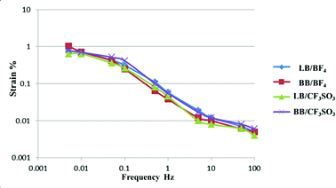 | ||
| Fig. 2 Strains (ε, %) calculated from the peak-to-peak displacement of the CNF/PEDOT:PSS/IL (50/200/200) electrode actuators as functions of the applied triangular voltage (±2 V) frequency. | ||
Table 1 summarizes the maximum strain of the four actuators consisting of two CNFs and ILs. These values depended on the CNF species (LB or BB). Strains observed for the CNF/PEDOT:PSS/IL (50/200/200) electrode actuator were greater than those observed for the CNF/PEDOT:PSS/IL (50/100/200) electrode actuators (Table S3†), and the strain measured for the CNF/PEDOT:PSS/EMI[BF4] electrode actuators exceeded those observed for the CNF/PEDOT:PSS/EMI[CF3SO3] electrode actuators. Furthermore, the strain for the BB/PEDOT:PSS/EMI[BF4] (50/200/200) electrode actuators was greater than those observed for the PEDOT:PSS/VGCF/IL32 electrode actuators. In addition, the strain for the CNF/PEDOT:PSS/IL (50/200/200) electrode actuators was greater than those observed for the PEDOT:PSS/IL33 electrode actuators (Table S4†). Thus, CNF/PEDOT:PSS/IL actuators are able to produce maximal strain, thereby making them suitable for use in actual applications, e.g., tactile displays.
| IL | LB/PEDOT | BB/PEDOT |
|---|---|---|
| EMI[BF4] | 0.74 | 1.04 |
| EMI[CF3SO3] | 0.64 | 0.78 |
As mentioned above, the CNF polymer in the CNF/PEDOT:PSS/IL actuator performed the role of the skeleton, whereas the PEDOT:PSS polymer in the CNF/PEDOT:PSS/IL actuator functioned as the base polymer and FC electrode.
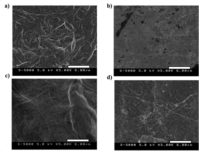
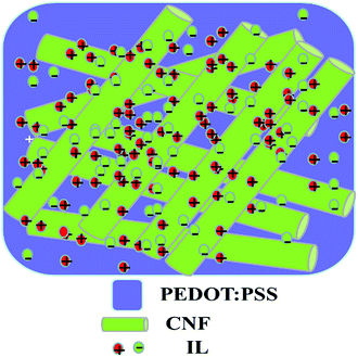
Fig. 3 shows the SEM images at 5000× magnification of (a) BB/EMI[BF4] = 100/200, (b) PEDOT:PSS/EMI[BF4] = 200/100, (c) BB/PEDOT:PSS/EMI[BF4] = 50/100/200, and (d) BB/PEDOT:PSS/EMI[BF4] = 50/200/200 electrode layers. The CNF/IL = 100/200 and CNF/PEDOT:PSS/IL electrodes exhibited similar trends in their morphologies. Fig. 3(a), (c), and (d) show that the electrode morphologies are a network of open pores formed by highly entangled CNFs, whereas Fig. 3(b) shows the absence of a network of open pores formed in the electrodes for PEDOT:PSS/EMI[BF4] = 200/100. The network of open pores in Fig. 3(a), (c), and (d) is indistinct and proportional to the amount of PEDOT:PSS. Therefore, the morphologies shown in Fig. 3(c) and (d) exhibit networks of open mesopores and pasted PEDOT:PSS polymer. Fig. 4 shows a schematic of the CNF/PEDOT:PSS/IL electrode (Fig. 3(c) and (d)).
Table 2 summarizes the Young's moduli of the four actuators containing two ILs. These values were independent of the CNF (LB or BB) and IL species. The Young's modulus of the CNF/PEDOT:PSS/IL (50/100/200) electrode exceeded those of both the CNF/PEDOT:PSS/IL (50/200/200) and the PEDOT:PSS/VGCF/IL electrodes.32 These data suggest that open mesopores in the form of a network were generated in the electrodes by the highly entangled CNF.30,38,39
| IL | LB/PEDOT | BB/PEDOT | LB/PEDOT | BB/PEDOT |
|---|---|---|---|---|
| 50/200/200 | 50/200/200 | 50/100/200 | 50/100/200 | |
| EMI[BF4] | 138 | 136 | 175 | 191 |
| EMI[CF3SO3] | 139 | 156 | 168 | 187 |
Finally, the maximum stress (σ) generated during actuation was calculated from the maximum strain (εmax) and Young's modulus (Y) using Hooke's law (σ = Y × εmax). Table 3 summarizes the σ values for the four actuators containing two ILs. The σ values depended on the CNF species (LB or BB). The maximum generated stress for the CNF/PEDOT:PSS/EMI[BF4] electrode actuators was greater than that of the CNF/PEDOT:PSS/EMI[CF3SO3] electrode actuators, and the σ values for the BB/PEDOT:PSS/IL electrode actuators were greater than those observed for the LB/PEDOT:PSS/IL electrode actuators. Moreover, the maximum generated stress values of the CNF/PEDOT:PSS/IL electrodes were greater than those obtained for the PEDOT:PSS/IL electrodes (Table S5†).33 Similar to the maximum strain, the maximum generated stress makes the CNF/PEDOT:PSS/IL actuators suitable for use in actual applications such as tactile displays.
| IL | LB/PEDOT | BB/PEDOT | LB/PEDOT | BB/PEDOT |
|---|---|---|---|---|
| 50/200/200 | 50/200/200 | 50/100/200 | 50/100/200 | |
| EMI[BF4] | 1.02 | 1.41 | 0.79 | 1.38 |
| EMI[CF3SO3] | 0.90 | 1.22 | 0.66 | 0.86 |
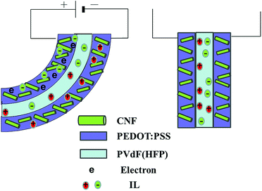
Our group previously reported the mechanism according to which a traditional PVdF–HFP/SWCNT/IL actuator undergoes bending.23 Namely, cations and anions are transferred from the gel electrolyte layer to the cathode and anode layers, respectively, when voltage is applied across the two electrode layers. This mechanism gives rise to the formation of an electrical double layer with nanotubes that are negatively and positively charged; in addition, the associated transportation of ions results in the cathode and anode layers experiencing shrinkage and swelling, respectively.23,29 Moreover, in the PEDOT/VGCF/IL actuator, as a result of ion migration, the anode layer swells and expands.32 This behavior of the anode layer is proposed to occur because of the contribution of the FC and EDLC mechanisms to the actuator motion at low frequencies. In addition, ion transport causes the cathode layer to swell and the anode layer to shrink. Consequently, the actuator bends in the direction of the anode (Fig. S1†).
In this work (CNF/PEDOT/IL actuator), the actuator motion was considered to take place mainly as a result of swelling and expansion of the anode layer according to the FC mechanism, with a minor contribution by the EDLC mechanism. In addition, ion transport caused the cathode and anode layers to swell and shrink, respectively. Thus, the actuator is deflected toward the anode (Fig. 5). In the newly developed actuator system, the electrode represented an electrochemical capacitor, which mainly comprised an FC and partially an EDLC, i.e., PEDOT:PSS, which behaved as an FC and a base polymer. Additionally, the CNF framework served as a replacement for VGCF.
A previous study24,27,32,33 examined the voltage–current and voltage–displacement characteristics of a bucky-gel actuator by applying a triangular waveform voltage at a range of frequencies. An electrochemical equivalent circuit model was proposed to describe the extent to which the frequency quantitatively depended on the generated strain. This model includes the combined resistance and capacitance of the electrode layer and combined resistance of the electrolyte layer and enables a time constant to be predicted for the response and low-frequency limit of the strain. This study successfully employed a similar kinetic model based on double-layer charging with FC (mainly) and EDLC (partially) mechanisms to predict variations in the frequency-dependent displacement of the CNF/PEDOT:PSS/IL electrode actuators (readers are referred to the ESI† for particulars).
Conclusions
This study led to the successful development of a novel CNT-free, self-standing actuator (CNF/PEDOT/IL), the operation of which can be described by an FC mechanism. The electrochemical and electromechanical properties of CNF/PEDOT/IL, PEDOT:PSS/VGCF/IL, and PEDOT/IL actuators were compared and this indicated that the FC mechanism predominantly explains the specific capacitance of the CNF/PEDOT:PSS/IL electrodes. This mechanism contrasts that proposed for PEDOT/VGCF/IL gel electrodes, for which only an FC and EDLC hybrid effect was observed, and that for polymer-supported PVdF–HFP/SWCNT/IL gel electrodes, which only exhibited the EDLC effect. Moreover, the CNF/PEDOT:PSS/IL actuators exhibited maximum strain and maximum generated stress that exceeded those exhibited by the PEDOT:PSS/IL devices. Similar to the PEDOT:PSS/CNT/IL actuators, a model of the variation in the displacement versus the frequency of the CNF/PEDOT:PSS/IL actuators was constructed using an equivalent circuit comprising an ionic resistance, an electrode resistance in series, and a double layer and faradaic capacitance. The flexible, robust films that are CNT free and self-standing with superior performance described in this paper are potentially suitable as an electrode material for wearable energy-conversion devices. It may be possible to extend this concept to additional CNF-based electrochemical materials intended for energy-conversion applications.Conflicts of interest
There are no conflicts to declare.Acknowledgements
This work was partly supported by the KAKENHI Grant-in Aid for Scientific Research C (17K05983) from JSPS.Notes and references
- A. Isogai, T. Saito and H. Fukuzumi, Nanoscale, 2011, 3, 71–85 RSC
.
- K. R. Prasad, K. Koga and N. Miura, Chem. Mater., 2004, 16, 1845–1847 CrossRef CAS
.
- M. Kalaji, P. J. Murphy and G. O. Williams, Synth. Met., 1999, 102, 1360–1361 CrossRef CAS
.
- Y. Zhou, B. He, W. Zhou, J. Huang, X. Li, B. Wu and H. Li, Electrochim. Acta, 2004, 49, 257–262 CrossRef CAS
.
- V. Gupta and N. Miura, Mater. Lett., 2006, 60, 1466–1469 CrossRef CAS
.
- L. Fan and J. Maier, Electrochem. Commun., 2006, 8, 937–940 CrossRef CAS
.
- A. Elschner, S. Kirchmeyer, W. Lövenich, U. Merker and K. Reuter, PEDOT: Principles and Applications of an Intrinsically Conductive Polymer, CRC Press: Taylor & Francis Group, Boca Raton, London, New York, 2011, vol. 10 Search PubMed
.
- J. Zhou, D. H. Anjum, G. Lubineau, E. Q. Li and S. T. Thoroddsen, Macromolecules, 2015, 48, 5688–5696 CrossRef CAS
.
- J. Zhou, E. Q. Li, R. Li, X. Xu, I. A. Ventura, A. Moussawi, D. H. Anjum, M. N. Hedhili, D.-M. Smilgies, G. Lubineau and S. T. Thoroddsen, J. Mater. Chem. C, 2015, 3, 2528–2538 RSC
.
- A. G. MacDiarmid, Angew. Chem., Int. Ed., 2001, 40, 2581–2590 CrossRef CAS PubMed
.
- D. Hohnholz, H. Okuzaki and A. G. MacDiarmid, Adv. Funct. Mater., 2005, 15, 51–56 CrossRef CAS
.
- H. Sirringhaus, T. Kawase, R. H. Friend, T. Shimoda, M. Inbasekaran, W. Wu and E. P. Woo, Science, 2000, 290, 2123–2126 CrossRef CAS PubMed
.
- H. Okuzaki, Y. Harashina and H. Yan, Eur. Polym. J., 2009, 45, 256–261 CrossRef CAS
.
- R. K. Cheedarala, J.-H. Jeon, C.-D. Kee and I.-K. Oh, Adv. Funct. Mater., 2014, 24, 6005–6015 CrossRef CAS
.
- S.-S. Kim, J.-H. Jeon, H. I. Kim, C.-D. Kee and I.-K. Oh, Adv. Funct. Mater., 2015, 25, 3560–3570 CrossRef CAS
.
- M. Kotal, J. Kim, K. J. Kim and I.-K. Oh, Adv. Mater., 2016, 28, 1610–1615 CrossRef CAS PubMed
.
- J. Zhou, T. Furukawa, H. Shirai and M. Kimura, Macromol. Mater. Eng., 2010, 295, 671–675 CrossRef CAS
.
- J. Zhou, M. Mulle, Y. Zhang, X. Xu, E. Q. Li, F. Han, S. T. Thoroddsen and G. Lubineau, J. Mater. Chem. C, 2016, 4, 1238–1249 RSC
.
- Directions for development of the field of Electroactive Polymer (EAP), ed. Y. Bar-Cohen, SPIE Press, Washington, DC, 2011 Search PubMed
.
- E. Smela, Adv. Mater., 2003, 15, 481–494 CrossRef CAS
.
- M. Shahinpoor, Electrochim. Acta, 2003, 48, 2343–2353 CrossRef CAS
.
- T. Fukushima, K. Asaka, A. Kosaka and T. Aida, Angew. Chem., Int. Ed., 2005, 44, 2410–2413 CrossRef CAS PubMed
.
- K. Mukai, K. Asaka, K. Kiyohara, T. Sugino, I. Takeuchi, T. Fukushima and T. Aida, Electrochim. Acta, 2008, 53, 5555–5562 CrossRef CAS
.
- I. Takeuchi, K. Asaka, K. Kiyohara, T. Sugino, K. Mukai, T. Fukushima and T. Aida, Electrochim. Acta, 2009, 53, 1762–1768 CrossRef
.
- T. Fukushima, A. Kosaka, Y. Ishimura, T. Yamamoto, T. Takigawa, N. Ishii and T. Aida, Science, 2003, 300, 2072–2074 CrossRef CAS PubMed
.
- W. Lu, A. G. Fadeev, B. Qi, E. Smela, B. R. Mattes, J. Ding, G. M. Spinks, J. Mazurkiewicz, D. Zhou, G. G. Wallace, D. R. MacFarlane, S. A. Forsyth and M. Forsyth, Science, 2002, 297, 983–987 CrossRef CAS PubMed
.
- N. Terasawa, I. Takeuchi and H. Matsumoto, Sens. Actuators, B, 2009, 139, 624–630 CrossRef CAS
.
- N. Terasawa, I. Takeuchi, H. Matsumoto, K. Mukai and K. Asaka, Sens. Actuators, B, 2011, 156, 539–545 CrossRef CAS
.
- I. Takeuchi, K. Asaka, K. Kiyohara, T. Sugino, N. Terasawa, K. Mukai and S. Shiraishi, Carbon, 2009, 47, 1373–1380 CrossRef CAS
.
- N. Terasawa, N. Ono, Y. Hayakawa, K. Mukai, T. Koga, H. Higashi and K. Asaka, Sens. Actuators, B, 2011, 160, 161–167 CrossRef CAS
.
- Q. Pei and O. Inganas, J. Phys. Chem., 1992, 96, 10507–10514 CrossRef CAS
.
- N. Terasawa and K. Asaka, Sens. Actuators, B, 2017, 248, 273–279 CrossRef CAS
.
- N. Terasawa and K. Asaka, Langmuir, 2016, 32, 7210–7218 CrossRef CAS PubMed
.
- J. P. Zheng and T. R. Jow, J. Electrochem. Soc., 1995, 142, L6–L8 CrossRef CAS
.
- H. Okuzaki, S. Takagi, F. Hishiki and R. Tanigawa, Sens. Actuators, B, 2014, 194, 59–63 CrossRef CAS
.
- M. Dietrich, J. Heinze, G. Heywang and F. Jonas, J. Electroanal. Chem., 1994, 369, 87–92 CrossRef CAS
.
- T. F. Otero, J. G. Martinez and J. Arias-PardillaT, Electrochim. Acta, 2012, 84, 112–128 CrossRef CAS
.
- Y. Zhang, Y. Shen, J. Li, L. Niu, S. Dong and A. Ivaska, Langmuir, 2005, 21, 4797–4800 CrossRef CAS PubMed
.
- R. H. Baughman, C. Cui, A. A. Zakhidov, Z. Iqbal, J. N. Barisci, G. M. Spinks, G. G. Wallace, A. Mazzoldi, D. De Rossi, A. G. Rinzler and O. Jaschinski, Science, 1999, 284, 1340–1344 CrossRef CAS PubMed
.
Footnote |
| † Electronic supplementary information (ESI) available. See DOI: 10.1039/c8ra06981f |
| This journal is © The Royal Society of Chemistry 2018 |

