DOI:
10.1039/C8RA06972G
(Paper)
RSC Adv., 2018,
8, 40267-40278
Damage characterization of red sandstones using uniaxial compression experiments
Received
20th August 2018
, Accepted 28th November 2018
First published on 3rd December 2018
Abstract
This paper proposes calculation formulae for damage variables that are characterized by four methods based on acoustic emission (AE), crack volume strain, a damage statistic constitutive model, and dissipation energy. Damage variables characterized by the four abovementioned methods are positively correlated to each other. An obvious inflection point exists in the curve of the damage variable characterized by AE and the strain, and the damage strength point is located before the inflection point. Both the high and low frequencies of the AE signals increase after the damage strength point, and the high-frequency signals mainly appear after the damage strength point, indicating that the damage strength point is located before the starting point for the formation of a large quantity of cracks. No obvious inflection point exists in the curve of the damage variable characterized by the crack volume strain and the strain; the curve is approximately a straight line before the peak stress point, and the damage strength point is located after the starting point of the approximate straight-line segment. Damage variable initially changes very slightly and begins to increase nonlinearly before the damage strength point; the curve is approximately a straight line after the damage strength point, and no obvious inflection point exists in the curve. Damage variable fluctuates slightly before the damage strength point and increases sharply in an approximately linear manner after the damage strength point. The damage strength point is located near the inflection point at which the damage variable begins to increase sharply, and the dissipation energy is the most effective method to identify the damage strength point. The value of the damage variable characterized by the crack volume strain is the largest whereas that characterized by the dissipation energy is the smallest. The value of the damage variable characterized by the crack volume strain is highly consistent with that of the damage variable characterized by AE, indicating that the crack volume strain is the most closely related parameter to AE.
1. Introduction
In the process of rock compression, the crack initiation strength (σci), damage strength (σcd), and peak strength (σf) are three important stress thresholds associated with the demarcation points between different damage stages of the process. The damage strength (σcd) represents the starting point of unstable crack extension. When the stress exceeds the damage strength, the cracks continue to extend unstably until the breaking of the rock even if the stress does not increase continuously but remains constant. Therefore, σcd is also referred to as the long-term strength of the rock and is an important index for representing the high-stress damage of hard rocks. This index is of great importance to the long-term stability of surrounding rocks.1 Researchers in both China and overseas have extensively studied the damage strength of rocks. For determining the damage strength of rocks, the two most commonly used methods include the AE method and the strain measurement method based on rock compression experiments.2
Martin et al.3,4 studied the damage strength of Lac du Bonnet granite by using the strain measurement method. They argued that the damage strength did not depend on the sample size and was approximately equal to 80% of the peak stress measured in the standard uniaxial compression test. They also performed a cyclic loading/unloading test, and the test results indicated that the damage strength was closely related to the accumulated amount of damage of the test sample. Lau et al.5 performed an incremental cyclic loading/unloading damage control test based on the strain measurement method and comprehensively studied the relationship between the damage strength and the accumulated damage due to cyclic loading/unloading under each cycle condition. Kim et al.6 performed a uniaxial compression test on KURT granite and recorded the stress, strain, and AE data simultaneously during the test. The test results showed that the damage strength was equal to 62–84% of the peak stress and that the maximum error of the damage strength determined by the strain measurement method and the AE method was 16%. In practice, the AE method is recommended for determining damage stress. Eberhardt et al.7 performed a uniaxial compression test by using the strain measurement method and found that the damage strength of pink Lac du Bonnet granite was equal to 75% of the peak stress. In addition, they analyzed the relationship among the accumulated damage, damage strength, and AE parameters under the cyclic loading/unloading condition and established the relationship between the stress and the accumulated damage parameters characterized by AE before the damage strength point.
Xue et al.8 discussed the influence of different measurement methods on the measured values of the damage strength of rocks in detail, and based on a large quantity of statistics found in the literature, they found that the ratio of the damage strength to the peak stress was almost never influenced by the type of rocks and the size of the mineral grains that constituted a rock. Chunsheng et al.9 performed a uniaxial compression test on marble samples acquired from the Baishan Formation at the Jinping-II Hydropower Station. The damage strength determined by the AE method was equal to 80% of the peak stress, and the test results were approximately the same as those for Lac du Bonnet granite. Using the strain measurement method, AE method, and longitudinal wave velocity measurement method, Bin et al.10 performed a uniaxial compression test and found that the damage strength of Jinping marble was equal to 82–86% of the peak stress. This indicated that the three methods were all able to determine the damage strength of the test samples accurately. Liang et al.11 and Wang et al.12 studied the relationship between the damage strength and the peak stress under loading conditions with different strain rates. Liang et al.11 also explored the law of change governing the damage stress of rocks and the strain energy at the peak stress point. Liu et al.13 used the relative volumetric strain stiffness method to measure the damage strength of marble under different ambient pressure conditions. The measurement results showed that the ratio of the damage strength to the peak stress reduced with an increase in the ambient pressure. Zhao et al.14 experimentally found that the damage strength could be determined accurately by using the accumulated AE impact count in conjunction with the stress and strain measurement. In addition, they discussed the dependence of the damage strength on the ambient pressure. Zhou et al.1,15 systematically summarized the four methods for calculating the crack initiation strength and damage strength of rocks and demonstrated the reliability of each calculation method. They also systematically studied the damage strength of granite and marble as well as the relationship between the damage strength and the ambient pressure.
The abovementioned domestic and foreign studies on the damage strength of rocks mainly focus on the following aspects: (1) specific methods for testing and determining the damage strength of rocks, (2) the influence of different loading conditions (including the ambient pressure and the loading rate) on the damage strength, and (3) the relationship between the damage strength and the damage parameters under a cyclic loading/unloading condition. The present study aims to obtain the relationship curves of the strain and the damage variables characterized by different methods and explore the law of change governing such damage variables at the damage strength point, thereby revealing the damage characteristics at the damage strength point. The study results will provide not only a basis for reasonably characterizing the damage variables at the damage strength point but also a certain scientific basis for recognizing the damage strength.
2. Experimental
2.1. Experimental program
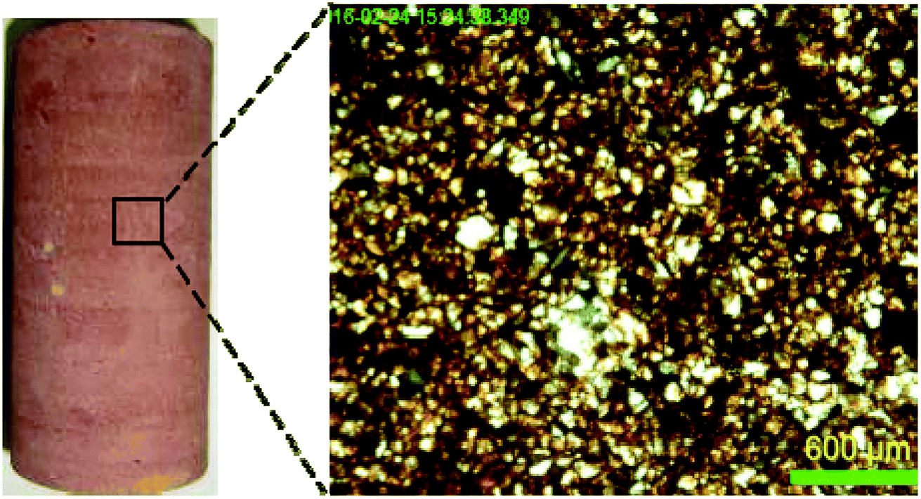
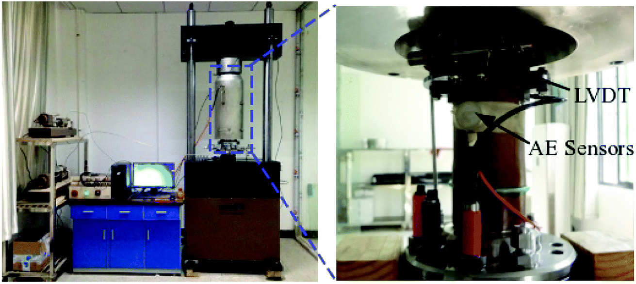
The test samples are hard and fragile coarse-grained red sandstones. Before the test, a polished thin section of the sandstones is created and its material composition is observed through electron microscopy imaging. The polished thin section contains mainly quartz and small amounts of feldspar, white mica, and heavy sand. The rock core is drilled and the end faces are polished to produce a few standard cylindrical test specimens with a height of 100 mm and a diameter of 50 mm. The end faces should be smooth, and the upper and lower end faces should be parallel to each other (the extent of nonparallelism should be less than 0.05 mm), as shown in Fig. 1. For the present test, 12 effective test specimens are created. For the uniaxial compression test, the loading system used is a triaxial rheometer for high-pressure rock temperature control (GDSVIS 400 kN, HPTAS, GDS Instruments, UK) and the AE system used is a sound emitter (PAC-II, Physical Acoustics, USA), as shown in Fig. 2. The AE sensors (UT1000) possess a wide operating frequency ranging from 1 kHz to 1 MHz. The damage strength is determined by using the volumetric strain method and the AE method so as to study various damage parameters at the damage strength point. During the complete loading process, data such as stress, strain, and time are acquired and appropriate relationship diagrams are drawn. The sound emitter is able to simultaneously acquire and record various parameters (including the energy, amplitude, ring count, center frequency, and peak frequency) and the signal waveform.
 |
| | Fig. 1 Photographs of the test specimen (left image) and corresponding microimage. | |
 |
| | Fig. 2 Illustration of the test equipment. | |
The present test mainly pertains to the stages before the peak stress but not the areas after the peak stress; therefore, the loading method used is based on load control. The loading rate is 0.1 MPa s−1. During the test, loading and AE monitoring should be carried out simultaneously. The sampling frequency of AE is set to 1 MHz, and the pregain and the trigger threshold are set to 40 dB. Two AE sensors were symmetrically mounted on the cylinder surface of the rock sample. And two groups of transverse and longitudinal gauges are respectively pasted on the two symmetrical sides in the middle of the test specimen, and the strain data acquisition interval is set to 0.5 s.
2.2. Determination of damage strength
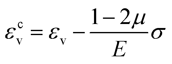
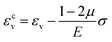
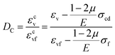
The crack volumetric strain method is widely used to determine crack initiation strength and damage strength. During the uniaxial compression test, the actual volume strain of the test specimen in the loading process is obtained according to the axial strain and radial strain:where εv refers to the measured volume strain, ε1 refers to the axial strain (in the uniaxial loading direction), and ε2 refers to the radial strain. The values for both ε1 and ε2 are obtained through the test.
The crack volume strain is equal to the measured volume strain minus the elastic volume strain. In a uniaxial compression state, the crack volume strain can be expressed as follows:
| |
 | (2) |
where
σ refers to the uniaxial loading stress,
E refers to the elastic modulus of the rock, and
μ refers to the Poisson's ratio of the rock.
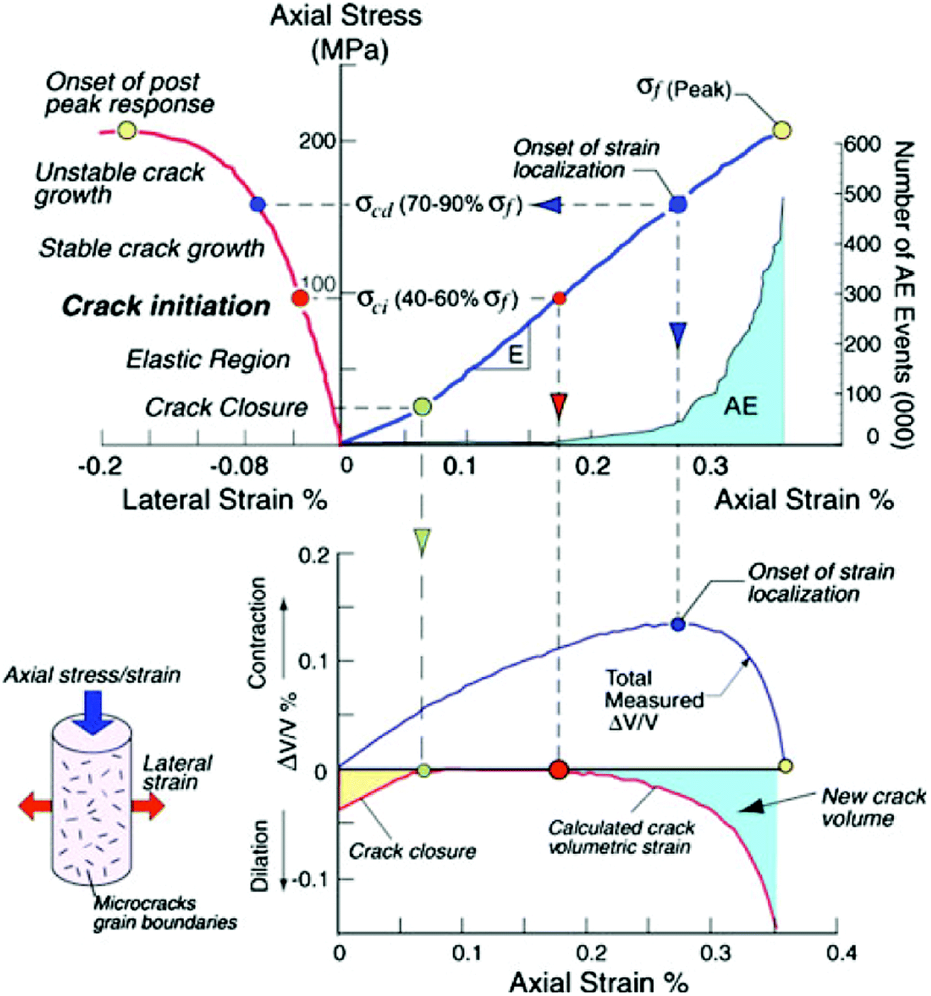
Damjanac and Fairhurst16 provides a key drawing for determining the damage stress by the volumetric strain method and the AE method, as shown in Fig. 3.17 When the volume strain begins to develop stably in the negative direction, the rock enters the expansion stage. The inflection point in the stress and volume strain curve indicates the volume expansion of the rock. The stress corresponding to the maximum volume strain point in this curve is the damage strength, which indicates the formation of unstable cracks. As indicated by Zhou et al.15 the above method for calculating the damage strength according to the inflection point of the volume strain of the test specimen has a definite physical meaning and can produce accurate results. For the purpose of engineering practicability, damage stress needs to be determined by the AE method.6 The present study also analyzes the AE characteristics of the damage strength. Therefore, the damage strength is also measured by the AE method in addition to the volumetric strain method.
 |
| | Fig. 3 Stages in the progressive failure of intact rock in compression (after Martin et al.17). | |
It is generally believed that cracks are more likely to develop and expand in the damage strength stage. In this stage, the number of AE events are clearly more than that in the earlier stage.9 The ring count can roughly reflect the strength and frequency of signals. Based on the literature on the determination of the damage strength by the AE method, this paper describes how to determine the damage strength in terms of the ring count.
3. Results and discussions
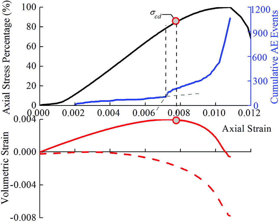
According to the test results, the damage strength is determined separately by the volumetric strain method and the AE method. The effective test results are obtained for eight test specimens in total. As an example, consider the test results for test specimen 5 (Fig. 4). The point at which the accumulated ring count increases sharply (the inflection point) is determined as the damage strength point. Table 1 lists the values of the ratio of the damage strength determined by the volumetric strain method and the AE method to the peak stress. The values of the volume strain at the damage strength point and the peak stress point are also listed in this table; these values are subsequently used to calculate the damage parameter at the damage strength point. The volumetric strain method is considered as an effective method to determine the damage strength point. Hereafter, unless otherwise noted, the damage strength point is considered to have been determined by the volumetric strain method.
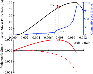 |
| | Fig. 4 Test result from the uniaxial test on specimen 5. | |
Table 1 The ratio of the damage strength determined by the volumetric strain method and the AE method to the peak stress
| Specimen number |
Volumetric strain corresponding to damage strength point (10−3) |
Volumetric strain corresponding to peak stress point (10−3) |
Ratio of damage strength and peak strength |
| Volumetric strain method |
AE method |
| 1 |
−1.29 |
−3.7 |
85% |
62% |
| 2 |
−0.45 |
−1.87 |
79% |
96% |
| 3 |
−0.5 |
−1.11 |
77% |
95% |
| 4 |
−0.99 |
−3.29 |
83% |
99% |
| 5 |
−2.29 |
−7.52 |
84% |
79% |
| 6 |
−0.94 |
−3.87 |
80% |
84% |
| 7 |
−0.34 |
−5.54 |
69% |
99% |
| 8 |
−1.48 |
−4.51 |
71% |
96% |
3.1. Damage variable characterization at damage strength point
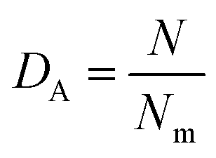
3.1.1. Damage variable characterized by AE. In the following sections, this paper assumes that the peak stress point represents a totally damaged state of the material. Based on a statistic model, Tang et al.18 assumed that the accumulative parameter pertaining to the AE in the process of rock loading is related to the extent of damage, as expressed below:| |
 | (3) |
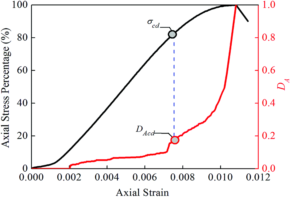
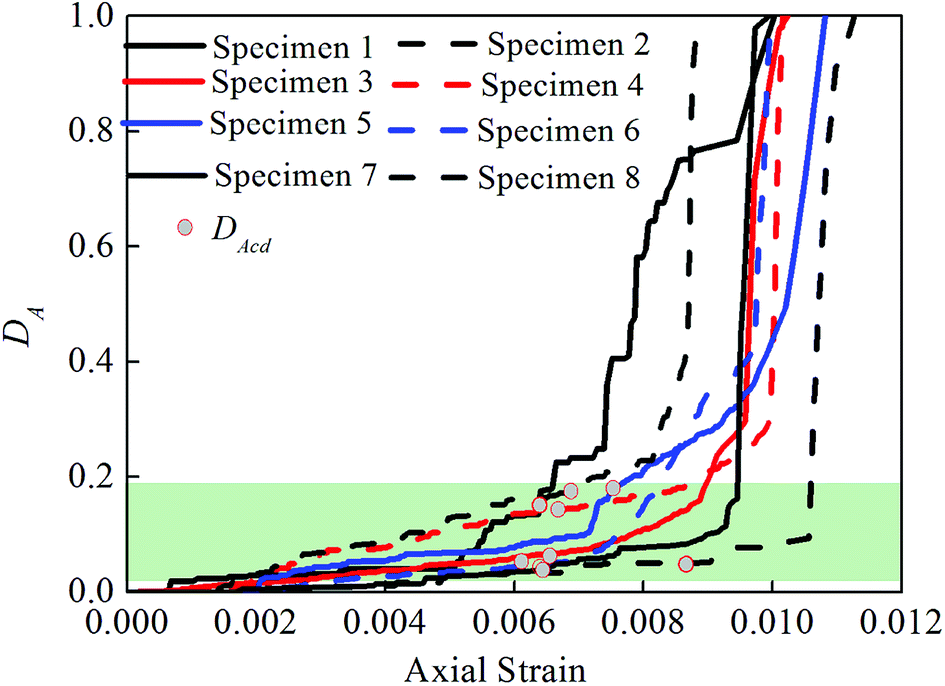
where DA refers to the damage variable characterized by the AE method, N refers to the accumulative parameter pertaining to AE, and Nm refers to the total accumulative parameter pertaining to AE. If N and Nm represent the accumulative parameters pertaining to the AE at the damage strength and peak stress points, respectively, the value of DA obtained by eqn (3) will be equal to the damage variable at the damage strength point; this parameter is denoted as DAcd. Fig. 5 shows the relationship curve of the strain and stress and the damage variable DA with respect to test specimen 5. Fig. 6 shows the relationship curves of the strain and the damage variable DA with respect to the eight test specimens.
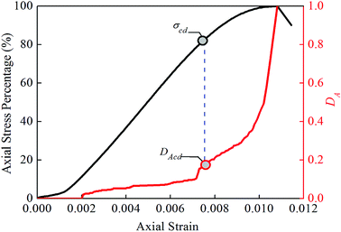 |
| | Fig. 5 The relationship between the strain and stress and the damage variable DA from the uniaxial test on specimen 5. | |
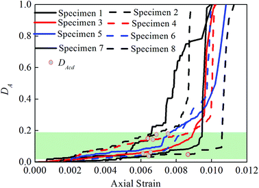 |
| | Fig. 6 The relationship curves of the strain and the damage variable DA with respect to the eight test specimens. | |
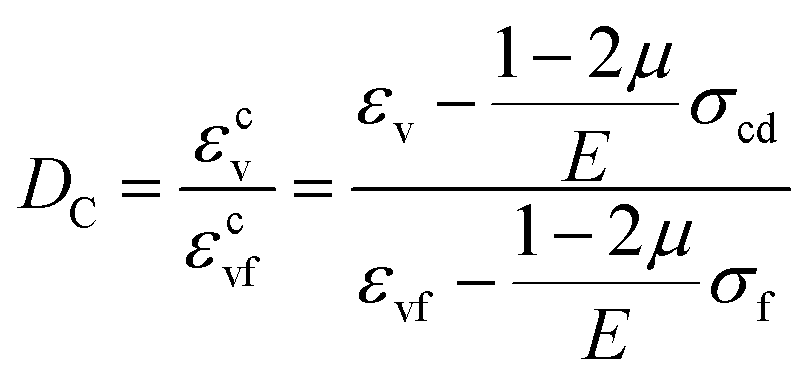
3.1.2. Damage variable characterized by crack volume strain. Chen et al.19 found that an internal relationship exists between AE and rock volume expansion. It is roughly estimated that the inelastic volume strain is in direct proportion to the total accumulated AE count, and the crack volume strain represents a kind of inelastic volume strain. Here, the damage variable (DC) is characterized in terms of the ratio of the crack volume strain in the process of rock loading to the crack volume strain at the peak stress point. A positive correlation clearly exists between DC and DA. According to eqn (2), the calculation formula for DC is obtained as follows:| |
 | (4) |
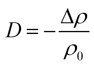
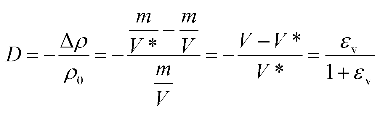
where the meanings of the various symbols are the same as those described above. If the crack volume strain εcv is equal to the crack volume strain εcvcd at the damage strength point, the value of DC obtained by eqn (4) is equal to that of the damage variable DCcd at the damage strength point.Kachanov20 proposed that the damage variable should be denoted in terms of the changing rate of density in creep damage; that is, the damage variable should be represented as follows:
| |
 | (5) |
where Δ
ρ refers to the changing rate of mass density of the material and
ρ0 refers to the mass density of the undamaged material. Lemaitre
et al.21 also proposed different forms of similar formulas for expressing the material damage variable in terms of the changing rate of density. For the uniaxial compression test of a rock, assume that the material mass is
m, the material volume in an undamaged state is
V, and the material volume in a damaged state is
V*. Then, the damage variable can be expressed as follows:
| |
 | (6) |
where
εv refers to the measured volume strain, which comprises the elastic volume strain and the crack volume strain. Because damage is closely related to the inelastic volume strain, it is obviously more reasonable to characterize the damage variable in terms of the crack volume strain in
eqn (6).
Fig. 7 shows the relationship curve of the strain and stress and the damage variable
DC with respect to test specimen 7, and
Fig. 8 shows the relationship curves of the strain and the damage variable
DC with respect to the eight test specimens. Before the threshold of the crack initiation strength is reached, the rock is still in the compaction and elastic stages, so these figures omit the damage variables before the threshold of the crack initiation strength.
 |
| | Fig. 7 The relationship between the strain and stress and the damage variable DC from the uniaxial test on specimen 7. | |
 |
| | Fig. 8 The relationship curves of the strain and the damage variable DC with respect to the eight test specimens. | |
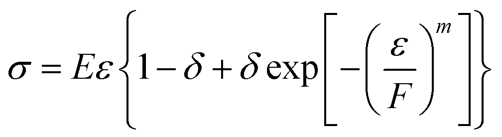
3.1.3. Damage variable characterized by damage statistic constitutive model. Assume that the rock strength is in conformity with the Weibull distribution law and that the statistical damage variable DS is defined as the ratio of the number of damaged microunits to the total number of microunits. According to the constitutive relationship based on the continuing medium damage theory, this paper obtains the damage statistic constitutive model of the rock under a uniaxial compression condition:22| |
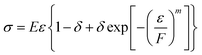 | (7) |
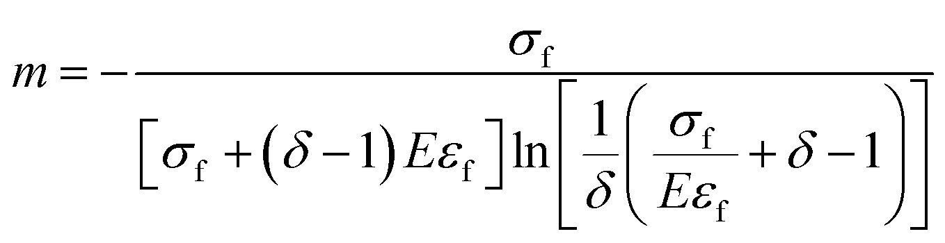
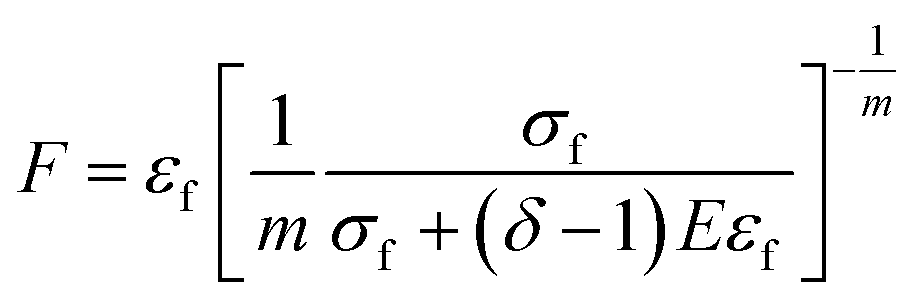
where ε refers to the strain, m and F are the parameters that characterize the physicomechanical properties of the rock material, and δ refers to the proportionality coefficient pertaining to rock damage (value ranges from 0 to 1).According to the uniaxial compression test curve, the calculation formulas for m and F are as follows:22
| |
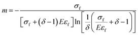 | (8) |
| |
 | (9) |
where
εf refers to the strain at the peak stress point.
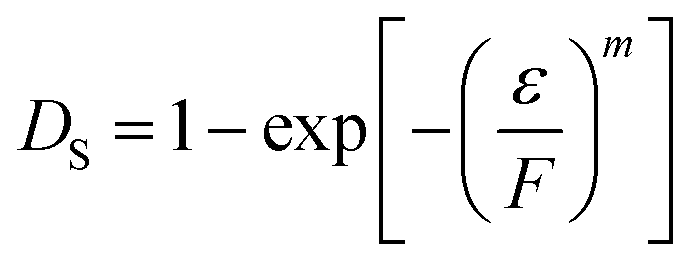
The damage variable DS can be calculated as follows:
| |
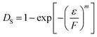 | (10) |
The m and F values calculated by eqn (9) are substituted into eqn (10), and then, the damage variable values associated with different stress or strain values are obtained. After the peak stress point, the rock material still has some residual strength and is not totally damaged. This study mainly analyzes the damage characteristics at the damage strength point and assumes that the rock material is totally damaged at the peak strength point. Therefore, the ratio of the damage variable in the process of rock loading to the damage variable DSf at the peak stress point is used to characterize the damage variable DSR:
| |
 | (11) |
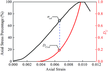
The damage variable DScd at the damage strength point is substituted into eqn (11). Then, the value of the damage variable DSRcd at the damage strength point is calculated. The proportionality coefficient δ pertaining to the rock damage is mainly used to reflect the residual strength of the rock; therefore, this section has mainly described the damage status before the peak stress point. Accordingly, the δ value is set to 1. According to eqn (8) and (9), the m and F values are obtained, and then, these values are substituted into eqn (7), thus determining the stress–strain relationship based on the damage statistic constitutive model. Fig. 9 shows the calculation results obtained using the damage statistic constitutive model with respect to test specimen 5. According to eqn (10) and (11), the relationship curve of the strain and stress and the damage variable DSR is obtained. Fig. 10 shows the relationship curves with respect to the eight test specimens.
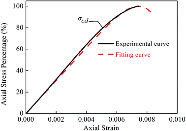 |
| | Fig. 9 Experimental curve and simulation curve of the uniaxial test on specimen 5. | |
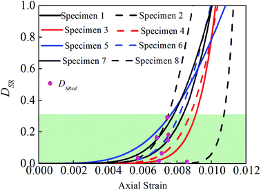 |
| | Fig. 10 The relationship curves of the strain and the damage variable DSR with respect to the eight test specimens. | |
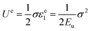
3.1.4. Damage variable characterized by dissipation energy. Assume no heat transfer in unit volume rock in the deformation process under exogenic action, and the energy from the work of the external force is U, then the equation can be get from the first law of thermodynamics:23where Ud is dissipation energy, Ue is elastic strain energy. For the uniaxial tests, U and Ue are:| |
 | (13) |
| |
 | (14) |
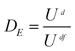
where εe1 is axial elastic strain, Eu is unloading elastic modulus, and can be simplified to initial elastic modulus E0.24Xie et al.23 proposed the damage formula characterized by dissipation energy. Then, the damage variable DE can be calculated as follow, assuming that the rock is complete damage at the peak stress point,
| |
 | (15) |
where
Udf is dissipation energy corresponding to peak stress point. Then, the value of the damage variable
DEcd at the damage strength point is calculated using
eqn (15).
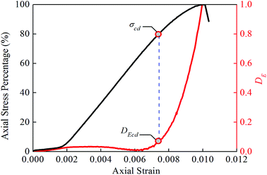
Fig. 11 shows the calculation results obtained using the damage statistic constitutive model with respect to test specimen 7.
Fig. 12 shows the relationship curves with respect to the eight test specimens.
 |
| | Fig. 11 The relationship between the strain and stress and the damage variable DE from the uniaxial test on specimen 7. | |
 |
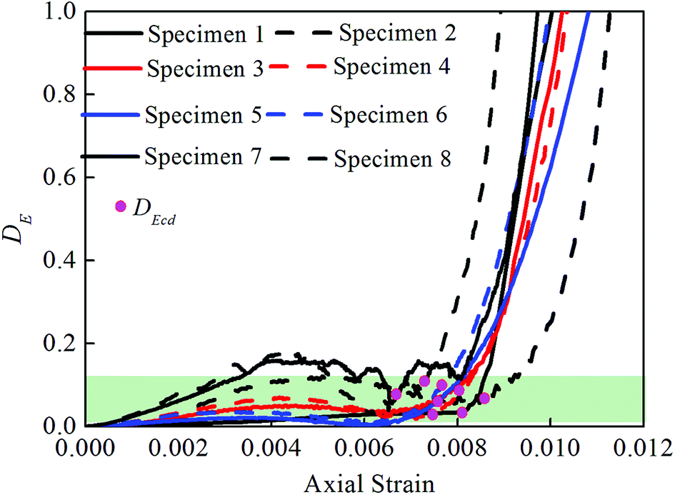
| | Fig. 12 The relationship curves of the strain and the damage variable DE with respect to the eight test specimens. | |
3.2. Discussion of damage characteristics in terms of damage strength
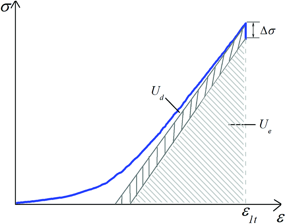
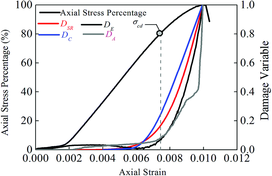
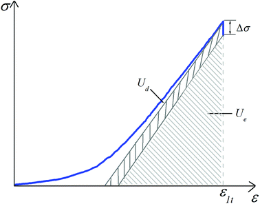
3.2.1. Comparison of damage variables characterized by different methods. The damage variable DC characterized by the crack volume strain has a definite physical meaning. In terms of physical relationships, DC is the most similar variable to the area-defined classic damage variable in damage mechanics. With the generation of microcracks inside a rock, elastic waves are radiated; this phenomenon is called AE. Moreover, new cracks are generated or the original cracks are extended, thus causing an increase in the rock volume. The newly increased volume is inelastic. Therefore, the generation process of rock microcracks will surely be reflected by the AE measurement or the volume strain measurement performed on the rock surface. An internal relationship exists between AE and rock volume expansion. It is roughly estimated that the inelastic volume strain is in direct proportion to the accumulated AE count.19 The recorded AE events account for only a very small portion of the total microcracks.25 Therefore, only an apparent positive correlation exists between the calculated damage variable DC and DA, and these variables are not necessarily in direct proportion to each other.In the process of compressive deformation of the rock, the dissipation energy is closely related to the damage process, for example, the formation and extension of cracks. Therefore, it can be deduced that the dissipation energy is positively correlated to the crack volume. The damage statistic constitutive model assumes that the rock strength is in conformity with the Weibull distribution law. Based on the stress–strain curves derived from the uniaxial compression test, this paper determines the parameters m and F that characterize the physicomechanical properties of the rock material and thus obtains the damage statistic constitutive model that is approximate to such stress–strain curves. According to eqn (7) and (10), the expression σ = Eε(1 − Ds) is obtained. Assume that the damage variable increases from Dst to Dst + ΔDst when the stress is ε1 = ε1t. Then, the corresponding stress decrement is Δσ = EεΔDst. As shown in Fig. 13, the increment in the dissipation energy is indicated by the shaded area. According to the definition of the damage variable characterized by the dissipation energy in eqn (15), it is obvious that the damage variable DE will also increase; that is, the damage variable characterized by the damage statistic constitutive model is positively correlated to the damage variable characterized by the dissipation energy. According to the above analysis, the damage variables characterized by the four methods are numerically different from each other, but their trends are consistent in the process of rock compression. This is also verified by the test results obtained in the study. Fig. 14 shows the relationship curves of the damage variables characterized by different methods and the stress and strain with respect to test specimen 7. The relationship curves with respect to the other test specimens are also similar.
 |
| | Fig. 13 Relationship of the damage statistic constitutive model and dissipation energy. | |
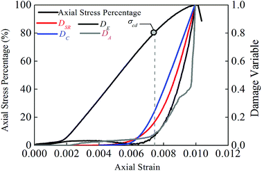 |
| | Fig. 14 The relationship curves of the damage variables characterized by different methods from the uniaxial test on specimen 7. | |
According to the test results of AE with respect to eight test specimens (Fig. 6), the damage variable characterized by AE increases steadily with an increase in the stress and then increases sharply before the peak stress point; an obvious inflection point appears, and the damage strength point is located before the inflection point. This indicates that the damage strength point is not the starting point for the formation of a large quantity of cracks but is the starting point at which a large quantity of cracks are in an embryonic state; as the stress increases, the cracks continue in this state until a macro-rupture occurs at the peak stress point. According to computational statistics, before the peak stress point, a difference of 15–30% exists between the stress percentages at the inflection and damage strength points. Apparently, the determination of the damage strength in terms of the inflection point of the damage variable curve is very error prone. The damage strength point is always located before the inflection point; therefore, it is feasible to use AE as an auxiliary means to identify the damage strength point.
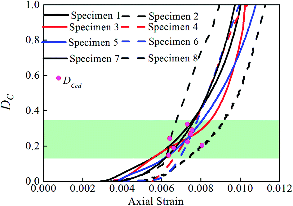
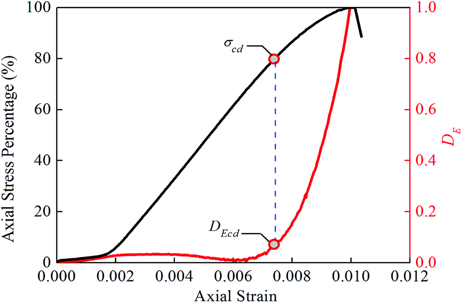
Fig. 8 shows the relationship curve of the strain and the damage variable characterized by the crack volume strain. No obvious inflection point is seen, the curve is approximately a straight line before the peak stress point, and the damage strength point is located after the starting point of the approximate straight-line segment. The identification of the damage strength point using this curve is difficult. Fig. 10 shows the relationship curve of the strain and the damage variable characterized by the damage statistic constitutive model. The damage variable initially changes very slightly, and no obvious inflection point is seen in the curve. Before the damage strength point, the damage variable begins to increase nonlinearly; after the damage strength point, the curve is approximately a straight line. The identification of the damage strength point using this curve is also difficult. Fig. 12 shows the relationship curve of the strain and the damage variable characterized by the dissipation energy. Before the damage strength point, the damage variable fluctuates within a small range and is very small overall. After the damage strength point, the damage variable increases sharply in an approximately linear manner. These observations are basically consistent with the results of the uniaxial compression test for red sandstone obtained in a previous study:26 in the initial compaction and elastic stages, the dissipation energy is very small and basically remains unchanged; in the plastic stage, the dissipation energy increases sharply in a nonlinear manner. It is worth noting that the curve of the damage variable characterized by the dissipation energy has an obvious inflection point, and the damage strength point is located near the sharp inflection point. According to computational statistics, a difference of 0–17% exists between the stress percentage at the inflection point before the peak stress point and that at the damage strength point. Therefore, the identification of the damage strength point is easier if the damage variable is characterized by the dissipation energy.
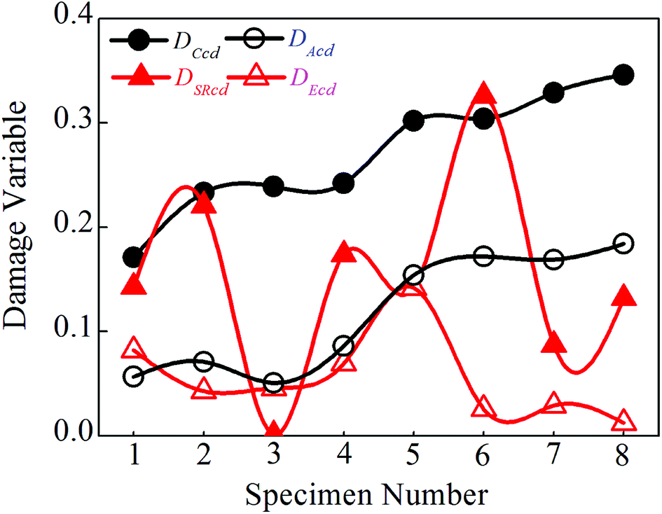
Fig. 15 shows the calculated values of the damage variables with respect to the eight test specimens. As shown in the Fig. 15, the values of the damage variable characterized by the crack volume strain (DCcd) are, on an average, equal to 0.27 at the damage strength point and are greater than the values of the damage variables characterized by the other three methods. The only exception is that the value of the damage variable characterized by the crack volume strain with respect to test specimen 6 is slightly smaller than the values of the damage variable characterized by the damage statistic constitutive model (DSRcd). The values of the damage variable characterized by the dissipation energy (DEcd) are, on an average, equal to 0.05 at the damage strength point and are smaller than the values of the damage variables characterized by the other three methods. The only exception is that the value of the damage variable characterized by the dissipation energy with respect to test specimen 1 is slightly greater than the values of the damage variable characterized by the AE (DAcd). The values of the damage variable characterized by the damage statistic constitutive model vary most significantly at the damage strength point. Specifically, the value of the damage variable with respect to test specimen 2 is the smallest (0.001) and that with respect to test specimen 6 is the largest (0.326). At the same time, Fig. 15 shows that among the calculated values of the damage variables at the damage strength point with respect to the eight test specimens, the values of the damage variable characterized by the crack volume strain are highly consistent with those characterized by the AE. This shows that crack volume strain is the most closely related parameter to AE.
 |
| | Fig. 15 Calculated data of the damage variables with respect to the eight test specimens. | |
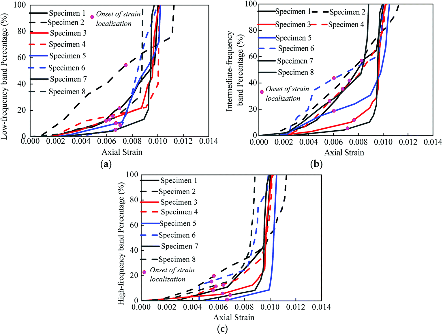
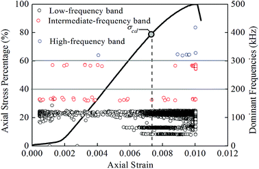
3.2.2. Characteristics of dominant frequencies of AE signals before/after damage strength point. The characteristics of frequency distribution can be obtained by transforming the AE waveform from the time domain to the frequency domain. In this paper, the dominant frequency is defined as the frequency associated with the maximum amplitude in the frequency spectrogram. According to the dominant distribution diagram derived from the test, three dominant frequency bands are observed: the low-frequency band (0–200 kHz), intermediate-frequency band (200–300 kHz), and high-frequency band (300–500 kHz). Fig. 16 shows the test results with respect to test specimen 7. To visually display the characteristics of dominant frequencies before/after the damage strength point with respect to the eight test specimens, a diagram of the percentage of different dominant frequencies and the strain–stress relationship in the uniaxial compression process is presented, as shown in Fig. 17.
 |
| | Fig. 16 Test result of three dominant frequency bands from the uniaxial test on specimen 7. | |
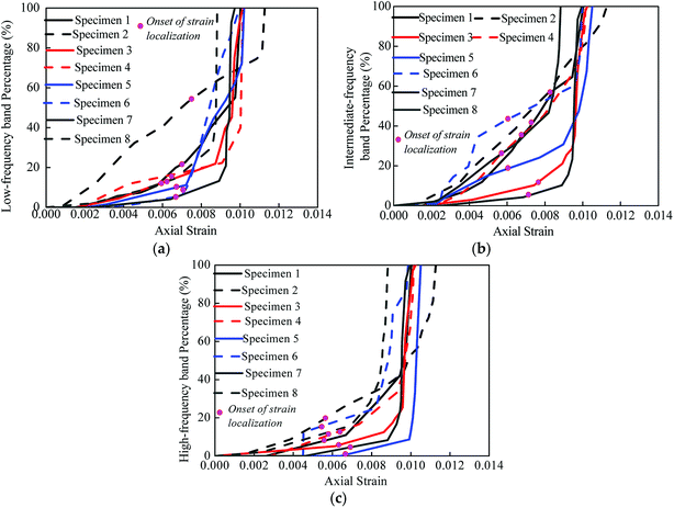 |
| | Fig. 17 The percentage of different dominant frequencies from the uniaxial tests: (a) low-frequency band, (b) intermediate-frequency band, (c) high-frequency band. | |
As shown in Fig. 16 and 17, the number of AE events before the damage strength point is smaller than that after the damage strength point, the AE events are mainly distributed in the low- and high-frequency bands, and the high-frequency AE events mainly occur after the damage strength point, accounting for 80% of the total high-frequency AE events. It is worth nothing that among the total AE events after the damage strength point, the low-, intermediate-, and high-frequency AE events account for 56%, 35%, and only 9% on an average, respectively. Kulakov and Yakovitskaya27 summarizes the frequency characteristics of the AE signals in different stages of rock loading and states that the occurrence of high-frequency AE events and the increase in low-frequency AE events serve as a premonitory symptom for the main rupture arising from a large quantity of cracks. Ji et al.28 investigated the frequency characteristics of AE in the uniaxial compression process of granite and drew the following conclusions: (1) the low-frequency AE signals play a dominant role among the total AE signals when the relative stress is very low (0–60%). (2) Both the low- and high-frequency AE signals increase to some extent, but the high-frequency AE signals increase more clearly in the plastic and final rupture stages, namely, the relative stress is higher than 80%. According to the test results presented here, the high-frequency AE events mainly occur after the damage strength point and the low-frequency AE events also increase simultaneously. Based on the research conclusions presented in previous papers,27,28 this paper draws the following conclusion from the perspective of the dominant frequency characteristics of AE signals: the internal damage in a rock is aggravated after the damage strength point, and then, the rock enters the plastic stage and the final rupture stage (main rupture stage).
4. Conclusions
Rock damage strength is an important eigenvalue that characterizes rock strength. Based on the existing research literature, this paper proposes calculation formulas for the damage variables that are characterized by four methods based on AE, crack volume strain, a damage statistic constitutive model, and dissipation energy. In addition, this paper explores the law of change governing the damage variable in the uniaxial compression process of red sandstones in detail and explicitly discusses the damage characteristics at the damage strength point. The research findings serve as a guide and a reference for an in-depth understanding of the damage characteristics at the damage strength point and for the accurate identification of the damage strength point. The main research findings are summarized as follows:
Based on the existing calculation method for the damage variable in the uniaxial compression process of rocks, this paper proposes calculation formulas for the damage variables that are characterized by four methods based on AE, crack volume strain, a damage statistic constitutive model, and dissipation energy. Both the test results and theoretical demonstration show that the damage variables characterized by the four methods are positively correlated to each other. The test results also show that the damage strength point is located before the point at which the damage variable begins to increase sharply.
In the relationship curve of the strain and the damage variable characterized by the AE, an obvious inflection point is seen, the damage strength point is located before the inflection point, and a difference of 15–30% exists between the stress percentages at the inflection and damage strength points. The determination of the damage strength in terms of the inflection point of the damage variable curve is very error prone. Because the damage strength point is located before the inflection point, it is feasible to use AE as an auxiliary means to identify the damage strength point.
In the relationship curve of the strain and the damage variable characterized by the crack volume strain, no obvious inflection point is seen, the curve is approximately a straight line before the peak stress point, and the damage strength point is located after the starting point of the approximate straight-line segment. In the relationship curve of the strain and the damage variable characterized by the damage statistic constitutive model, the damage variable initially changes very slightly and begins to increase nonlinearly before the damage strength point, the curve is approximately a straight line after the damage strength point, and no obvious inflection point is seen.
In the relationship curve of the strain and the damage variable characterized by the dissipation energy, the damage variable fluctuates slightly before the damage strength point and increases sharply in an approximately linear manner after the damage strength point, the damage strength point is located near the inflection point at which the damage variable begins to increase sharply, and a difference of 0–17% exists between the stress percentages at the inflection and damage strength points. Therefore, the method based on the dissipation energy is the most effective one to identify the damage strength point.
At the damage strength point, the value of the damage variable characterized by the crack volume strain is the largest whereas that characterized by the dissipation energy is the smallest. The value of the damage variable characterized by the crack volume strain is highly consistent with that characterized by the AE, indicating that crack volume strain is the most closely related parameter to AE.
High-frequency AE events mainly occur after the damage strength point, and the count of low-frequency AE events increases after the damage strength point. Judging by the characteristics of the dominant frequency of AE signals, the internal damage in a rock is aggravated after the damage strength point, and then, the rock enters the plastic and final rupture stages.
Author contributions
Z. H. and B. Y. designed and performed the experiments. K. Z. and Z. H. developed the idea of the research, supervised the research, and wrote the paper.
Conflicts of interest
The authors declare no conflict of interest.
Acknowledgements
This work was supported by the National Natural Science Foundation of China (51364012, 51664018 and 41702326), the National Postdoctoral Program for Innovative Talents (BX201700113), the China Postdoctoral Science Foundation (2017M620205), the State Key Laboratory for GeoMechanics and Deep Underground Engineering, China University of Mining & Technology (SKLGDUEK1703), the Natural Science Foundation of Jiangxi Province (20171BAB206022), and the Science and Technology Project Founded by the Education Department of Jiangxi Province (GJJ160675). The authors gratefully acknowledged the helpful comments and suggestions given by the editors and anonymous reviewers.
References
- H. Zhou, F. Z. Meng, C. Q. Zhang, F. J. Yang and J. J. Lu, Characteristics and mechanism of occurrence of stress thresholds and corresponding strain for hard rock, Chin. J. Rock Mech. Eng., 2015, 34(8), 1513–1521 Search PubMed.
- E. Ghazvinian, M. S. Diederichs, D. Labrie and C. D. Martin, An investigation on the fabric type dependency of the crack damage thresholds in brittle rocks, Geotechnical and Geological Engineering, 2015, 33, 1409–1429 CrossRef.
- C. D. Martin, The strength of massive Lac du Bonnet granite around underground openings. University of Manitoba, Manitoba, Canada, 1993 Search PubMed.
- C. D. Martin and N. A. Chandler, The progressive fracture of Lac du Bonnet granite, Int. J. Rock Mech. Min. Sci. Geomech. Abstr., 1994, 31, 643–659 CrossRef.
- J. S. O. Lau and N. A. Chandler, Innovative laboratory testing, Int. J. Rock Mech. Min. Sci., 2004, 41, 1427–1445 CrossRef.
- J. S. Kim, K. S. Lee, W. J. Cho, H. J. Choi and G. C. Cho, A comparative evaluation of stress–strain and acoustic emission methods for quantitative damage assessments of brittle rock, Rock Mech. Rock Eng., 2015, 48, 495–508 CrossRef.
- E. Eberhardt, D. Stead and B. Stimpson, Quantifying progressive pre-peak brittle fracture damage in rock during uniaxial compression, Int. J. Rock Mech. Min. Sci., 1999, 36, 361–380 CrossRef.
- L. Xue, S. Qin, Q. Sun, Y. Wang and L. M. Lee, A study on crack damage stress thresholds of different rock types based on uniaxial compression tests, Rock Mech. Rock Eng., 2014, 47, 1183–1195 CrossRef.
- C. S. Zhang, X. R. Chen, J. Hou and W. J. Chu, Study of mechanical behavior of deep-buried marble at Jinping II Hydropower Station, Chin. J. Rock Mech. Eng., 2010, 29(10), 1999–2009 Search PubMed.
- B. Wang, J. B. Zhu, P. Yang, S. L. Huang and A. Q. Wu, Damage strength determination of marble and its parameters evaluation based on damage control test, Chin. J. Rock Mech. Eng., 2012, 31(Suppl. 2), 3967–3973 Search PubMed.
- C. Y. Liang, X. Li, S. X. Wang, S. D. Li, J. M. He and C. F. Ma, Experimental investigation on rate-dependent stress-strain characteristics and energy mechanism of rock under uniaxial compression, Chin. J. Rock Mech. Eng., 2012, 31(9), 1830–1838 Search PubMed.
- H. L. Wang, P. X. Fan, M. Y. Wang, W. P. Li and Y. H. Qian, Influence of strain rate on progressive failure process and characteristic stresses of red sandstone, Rock Soil Mech., 2011, 32(5), 1340–1346 Search PubMed.
- N. Liu, C. S. Zhang and W. J. Chu, Fracture characteristics and damage evolution law of Jinping deep marble, Chin. J. Rock Mech. Eng., 2012, 31(8), 1606–1613 Search PubMed.
- X. G. Zhao, L. Ma, R. Su and J. Wang, Fracture evolution and strength characteristics of Beishan deep granite under compression conditions, Chin. J. Rock Mech. Eng., 2014, 33(Suppl. 2), 3665–3675 Search PubMed.
- H. Zhou, F. Z. Meng, J. J. Lu, C. Q. Zhang and F. J. Yang, Discussion on methods for calculating crack initiation strength and crack damage strength for hard rock, Rock Soil Mech., 2014, 35(4), 913–918 Search PubMed.
- B. Damjanac and C. Fairhurst, Evidence for a long-term strength threshold in crystalline rock, Rock Mech. Rock Eng., 2010, 43(5), 513–531 CrossRef.
- C. D. Martin, The effect of cohesion loss and stress path on brittle rock strength, Can. Geotech. J., 1997, 34, 698–725 CrossRef CAS.
- C. A. Tang, Z. H. Chen, X. H. Xu and C. A. Li, Theoretical model for Kaiser effect in rock, Pure Appl. Geophys., 1997, 150, 203–215 CrossRef.
- Y. Chen, T. F. Huang and E. L. Liu, Rock physics. China Science and Technology Press: Beijing, China, 2009 Search PubMed.
- L. M. Kachanov, Theory of creep in advances in creep design. Applied Sciences Publisher, London, 1985 Search PubMed.
- J. Lemaitre, Damage measurement, Eng. Fract. Mech., 1987, 28(5/6), 643–660 CrossRef.
- S. Q. Yang, Study on the mechanical behavior of fissured rock and time-dependent effect analysis. Science Press: Beijing, China, 2011 Search PubMed.
- H. P. Xie, Y. Ju and L. Y. Li, Criteria for strength and structural failure of rocks based on energy dissipation and energy release principles, Chin. J. Rock Mech. Eng., 2005, 24(17), 3003–3010 Search PubMed.
- D. Huang, R. Q. Huang and Y. X. Zhang, Experimental investigation on static loading rate effects on mechanical properties and energy mechanism of coarse crystal grain marble under uniaxial compression, Chin. J. Rock Mech. Eng., 2012, 31(2), 245–255 CAS.
- S. Y. Li, T. M. He and X. C. Yin, Introduction of fracture mechanics of rock. University of Science and Technology of China Press: Heifei, China, 2010 Search PubMed.
- Q. B. Meng, L. J. Han, H. Pu, S. Y. Wen, H. Li and H. Li, Experimental on the effect of strain rate and size on the energy accumulation and dissipation of rock, J. China Coal Soc., 2015, 40(10), 2386–2398 Search PubMed.
- G. I. Kulakov and G. E. Yakovitskaya, Acoustic emission and stages of the crack-formation process in rock, J. Min. Sci., 1993, 29(2), 111–114 CrossRef.
- H. G. Ji, H. W. Wang, S. Z. Cao, Z. F. Hou and Y. Jin, Experimental research on frequency characteristics of acoustic emission signals under uniaxial compression of granite, Chin. J. Rock Mech. Eng., 2012, 31(Supp. 1), 2900–2905 Search PubMed.
|
| This journal is © The Royal Society of Chemistry 2018 |
Click here to see how this site uses Cookies. View our privacy policy here. 
 Open Access Article
 This Open Access Article is licensed under a Creative Commons Attribution-Non Commercial 3.0 Unported Licence
 *ab and
Bin Yua
*ab and
Bin Yua