 Open Access Article
Pure phase synthesis of Cu3PS4 and Cu6PS5Cl for semiconductor applications†
Brian Graeser and
Rakesh Agrawal *
*
Davidson School of Chemical Engineering, Purdue University, 480 Stadium Mall Drive, West Lafayette, IN 47907, USA. E-mail: agrawalr@purdue.edu
First published on 3rd October 2018
Abstract
We have achieved the first reported pure phase synthesis of two new nanoparticle materials, Cu3PS4 and Cu6PS5Cl. We have achieved this through learning about the potential reaction pathways that CuCl2, P2S5, and 1-dodecanethiol can take. This study has shown that the key variable to control is the state of the phosphorus source when the CuCl2 is added. If P2S5 is added together with the CuCl2 to dodecanethiol then the reaction will follow a path to Cu3PS4, but if it is dissolved in dodecanethiol prior to the addition to CuCl2 then the reaction will produce Cu6PS5Cl. The formation of these two different phases can occur simultaneously, yet we have found sets of conditions that manipulate the reaction system to form each phase exclusively. These nanoparticles could have broad semiconductor or solid electrolyte applications.
There is a need to explore new thin film photovoltaic absorbers, as many of the current thin film technologies have challenges associated with them. The high efficiency materials such as CuInxGa1−xSe2 (ref. 1–5) and CdTe,6–8 require the use of the less-abundant elements indium and tellurium. To rectify this short coming, materials that use earth abundant elements such as Cu2ZnSnSe4 (CZTSe)9,10 and amorphous-Si11–13 have been explored. This class of materials has been unable to reach the efficiencies of the CuInxGa1−xSe2 and CdTe cells that are necessary to become an economic alternative to fossil fuel based energy. Specifically in the case for CZTSe, the issue is caused by intrinsic defect formation, leading to band tails in the material.14–17 This defect is caused by the zinc on copper site (CuZn) and the accompanying copper on zinc (ZnCu) site.18,19 This is due to the similar sizes of the Cu1+ and the Zn2+ ions.
Because of the uncertainties regarding the limitations and future of previously developed earth abundant materials for solar cells, it is necessary to investigate new materials that avoid the pitfalls that have hampered the previous technologies. It has been proposed to use a Cu3–V–VI4 (V = P, As, Sb; VI = S, Se) structured material to address these issues.20–28 This class of materials uses earth abundant cations to allow for production on a terawatt scale. They also avoid the cation switching that has hampered the efficiencies of CZTSe devices, due to the mismatch between the sizes of V5+ and Cu1+ cations.
Some work examining the phosphorus member of the Cu3–V–VI4 material family and its potential use as a solar absorber material has been reported in the literature. The reported calculations have estimated that the band gap of the selenide material is within the ideal range of 1.0–1.5 eV, and they have potential for the power conversion efficiencies to be greater than that of CuInSe2. Experimental studies have confirmed the band gap of Cu3PSe4 to be 1.35 eV.22 On the other hand, Cu3PS4 with a higher band gap is a potential candidate for a top cell in a tandem cell. Both of the materials have shown a photoelectric response,22,23 and could be attractive materials for photovoltaic devices.
In the past, crystals of Cu3PS4 have been synthesized either using chemical vapor transport and temperatures in excess of 850 °C for long periods of time such as 24 hours20,29 or heating elemental powders of copper, phosphorus and sulfur in sealed evacuated fused silica tubes at high temperatures for extended time periods.22,27,30 While these techniques produce crystals of Cu3PS4 that could be used for fundamental characterization, they are not suitable for fabrication of thin films of Cu3PS4. There is a need to pursue and develop new solution based techniques for the synthesis of Cu3PS4, if it is to be competitive with other thin film technologies. Using nanoparticles as a method for forming thin films has been employed for a variety of other materials for PV applications.1,9,31,32
The previous solution-based method, to synthesize Cu3PS4 nanoparticles has faced significant obstacles.23 This method is based on reducing both copper and phosphorus to a neutral state and reacting them together to form Cu3P nanoparticles. These nanoparticles are then reacted with thiourea in a separate reaction. While this procedure does produce Cu3PS4 nanoparticles, they are not pure phase. There is the presence of a phosphorus rich phase that is altering the composition and effecting the photoluminescence. If Cu3PS4 nanoparticles are to be used a precursor to a solar absorber, they will need to be free of any contaminants that could adversely affect a final film.
For this contribution we have examined copper–phosphorus–sulfide system. This material can occur in two main phases, the Cu3PS4 enargite phase and the Cu7PS6 argyrodite phase. The argyrodite structure also has a chloride phase compound Cu6PS5Cl. The enargite phase is of more interest for photovoltaic applications, as either a top material for a multi-junction device or for use in high band gap electronic devices.
Argyrodites, while they may not be useful as solar absorbers, have been explored for use as solid electrolytes.33–35 Cu6PS5Cl has been of particular interest due to its high performance and copper mobility.36,37 This material has shown better conductivities than other materials in the same family. In a similar case to the enargite materials, synthesis of the argyrodites is done in sealed ampule or vacuum based methods.34–37
Experimental
Co-addition of CuCl2 and P2S5 powders at room temperature for solvothermal nanoparticle synthesis
In a nitrogen filled glovebox, copper(II) chloride (Sigma-Aldrich, ≥99.995% trace metals basis, CuCl2) and phosphorus pentasulfide (Acros Organics, 98+%, P2S5) are added to a reaction flask in either stoichiometric amounts or 50% excess phosphorus (Cu![[thin space (1/6-em)]](https://www.rsc.org/images/entities/char_2009.gif) :
:![[thin space (1/6-em)]](https://www.rsc.org/images/entities/char_2009.gif) P 2
P 2![[thin space (1/6-em)]](https://www.rsc.org/images/entities/char_2009.gif) :
:![[thin space (1/6-em)]](https://www.rsc.org/images/entities/char_2009.gif) 1) content followed by 4 mL of 1-dodecanethiol (Sigma-Aldrich, ≥98%, DDT). This flask is heated to 250 °C under an argon atmosphere and held at that temperature for 1 hour. Then the flask is allowed to cool to room temperature in ambient conditions. After nanoparticles reach room temperature, they are dispersed in a hexane and isopropanol mixture (V
1) content followed by 4 mL of 1-dodecanethiol (Sigma-Aldrich, ≥98%, DDT). This flask is heated to 250 °C under an argon atmosphere and held at that temperature for 1 hour. Then the flask is allowed to cool to room temperature in ambient conditions. After nanoparticles reach room temperature, they are dispersed in a hexane and isopropanol mixture (V![[thin space (1/6-em)]](https://www.rsc.org/images/entities/char_2009.gif) :
:![[thin space (1/6-em)]](https://www.rsc.org/images/entities/char_2009.gif) V 1
V 1![[thin space (1/6-em)]](https://www.rsc.org/images/entities/char_2009.gif) :
:![[thin space (1/6-em)]](https://www.rsc.org/images/entities/char_2009.gif) 5) and precipitated using centrifugation at 14k rpm for 5 minutes. This washing is done three times and afterwards the nanoparticles are dried under dry nitrogen.
5) and precipitated using centrifugation at 14k rpm for 5 minutes. This washing is done three times and afterwards the nanoparticles are dried under dry nitrogen.
Phosphorus pentasulfide pre-dissolution nanoparticle reaction
P2S5 and 1-dodecanethiol are added to a reaction flask under a nitrogen atmosphere, and the flask heated under an argon atmosphere to 250 °C and is held for 1 hour. Then it is cooled to ambient temperature. The flask is opened in a nitrogen atmosphere, and CuCl2 is added to the flask, which is resealed. The flask is heated to 250 °C under argon and is held for 1 hour, then is cooled to room temperature. The particles are dispersed in a hexane and isopropanol mixture (V![[thin space (1/6-em)]](https://www.rsc.org/images/entities/char_2009.gif) :
:![[thin space (1/6-em)]](https://www.rsc.org/images/entities/char_2009.gif) V 1
V 1![[thin space (1/6-em)]](https://www.rsc.org/images/entities/char_2009.gif) :
:![[thin space (1/6-em)]](https://www.rsc.org/images/entities/char_2009.gif) 5) and are precipitated out by centrifuging at 14k rpm for 5 min. This is done three times, and then the nanoparticles are dried in nitrogen.
5) and are precipitated out by centrifuging at 14k rpm for 5 min. This is done three times, and then the nanoparticles are dried in nitrogen.
Characterization
X-ray diffraction data was gathered using a Rigaku SmartLab diffractometer with a Cu Kα X-ray source. Raman spectra were acquired using a Horiba/Jobin-Yvon LabRAM HR 800 confocal microscope with a 633 nm He:Ne laser. Samples for XRD and Raman spectroscopy were made by drop casting the particles in hexane onto soda-lime glass. UV-Vis was collected by an Agilent Technologies Cary 60 spectrophotometer. Scanning electron microscopy energy dispersive X-ray spectroscopy data (SEM-EDS). Transmission electron microscopy (TEM) for the Cu3PS4 nanoparticles was done on a Hitachi 2700-C, and for the Cu6PS5Cl nanoparticles s FEI Talos F200X was used.Results and discussion
We wanted to design a single pot synthesis to simplify the Cu3PS4 synthesis and to avoid complications from having multiple steps. For this material in particular there have been issues with residual phosphorus staying on the nanoparticles after an earlier reaction that stays with the nanoparticles through subsequent reactions. Other reaction pathways that use multiple steps could have possibilities for other impurities to be left behind. This means that we need to have our copper, phosphorus, and sulfur source all present and active in our initial reaction.Synthesis of Cu3PS4
We synthesized pure phase Cu3PS4 nanoparticles by the novel co-addition of CuCl2 and P2S5 powders (Cu![[thin space (1/6-em)]](https://www.rsc.org/images/entities/char_2009.gif) :
:![[thin space (1/6-em)]](https://www.rsc.org/images/entities/char_2009.gif) P 2
P 2![[thin space (1/6-em)]](https://www.rsc.org/images/entities/char_2009.gif) :
:![[thin space (1/6-em)]](https://www.rsc.org/images/entities/char_2009.gif) 1) at room temperature for nanoparticle synthesis method. The PXRD and Raman spectra are shown in Fig. 1. All peaks seen in those spectra can be assigned to Cu3PS4. The phase purity of nanoparticles was confirmed by Rietveld refinement (see ESI†), which found no evidence of the presence of Cu6PS5Cl and did not find any unexplained peaks. The composition for the nanoparticles was examined through SEM-EDX (see Table 1), and it showed that the nanoparticles are very close to the expected composition but are slightly phosphorus rich and copper poor. The near stoichiometric composition of 3
1) at room temperature for nanoparticle synthesis method. The PXRD and Raman spectra are shown in Fig. 1. All peaks seen in those spectra can be assigned to Cu3PS4. The phase purity of nanoparticles was confirmed by Rietveld refinement (see ESI†), which found no evidence of the presence of Cu6PS5Cl and did not find any unexplained peaks. The composition for the nanoparticles was examined through SEM-EDX (see Table 1), and it showed that the nanoparticles are very close to the expected composition but are slightly phosphorus rich and copper poor. The near stoichiometric composition of 3![[thin space (1/6-em)]](https://www.rsc.org/images/entities/char_2009.gif) :
:![[thin space (1/6-em)]](https://www.rsc.org/images/entities/char_2009.gif) 1 Cu
1 Cu![[thin space (1/6-em)]](https://www.rsc.org/images/entities/char_2009.gif) :
:![[thin space (1/6-em)]](https://www.rsc.org/images/entities/char_2009.gif) P produced by this synthesis demonstrates an improvement over the 1
P produced by this synthesis demonstrates an improvement over the 1![[thin space (1/6-em)]](https://www.rsc.org/images/entities/char_2009.gif) :
:![[thin space (1/6-em)]](https://www.rsc.org/images/entities/char_2009.gif) 1 Cu
1 Cu![[thin space (1/6-em)]](https://www.rsc.org/images/entities/char_2009.gif) :
:![[thin space (1/6-em)]](https://www.rsc.org/images/entities/char_2009.gif) P ratio seen in previous studies.23 This extreme phosphorus excess was hypothesized to be caused by a presence of elemental phosphorus on the surface of the nanoparticles. We attribute the lack of the extra phosphorus in our synthesis to the final solubility of the P2S5 in the dodecanethiol. Since the P2S5 remained soluble at room temperature any excess can be removed with the solvent using a washing step. Typically this washing is done using isopropanol to remove any excess species from the nanoparticles.
P ratio seen in previous studies.23 This extreme phosphorus excess was hypothesized to be caused by a presence of elemental phosphorus on the surface of the nanoparticles. We attribute the lack of the extra phosphorus in our synthesis to the final solubility of the P2S5 in the dodecanethiol. Since the P2S5 remained soluble at room temperature any excess can be removed with the solvent using a washing step. Typically this washing is done using isopropanol to remove any excess species from the nanoparticles.
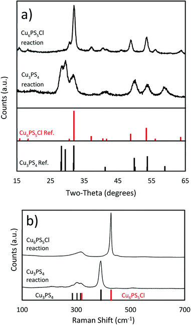 | ||
| Fig. 1 (a) PXRD spectra (Cu3PS4 standard JCPDS: 01-071-3306, Cu6PS5Cl standard JCPDS: 01-073-5736) and (b) Raman spectra of the Cu3PS4 and Cu6PS5Cl nanoparticles. | ||
| Element | Cu | P | S | Cl |
|---|---|---|---|---|
| Cu3PS4 | 2.84 | 1 | 3.81 | 0 |
| Cu6PS5Cl | 5.42 | 1 | 5.48 | 0.44 |
Synthesis of Cu6PS5Cl
We were also able to synthesize pure phase Cu6PS5Cl nanoparticles by the phosphorus pentasulfide pre-dissolution nanoparticle reaction. The amount of P2S5 pre-dissolved in DDT and added CuCl2 lead to Cu![[thin space (1/6-em)]](https://www.rsc.org/images/entities/char_2009.gif) :
:![[thin space (1/6-em)]](https://www.rsc.org/images/entities/char_2009.gif) P of 2
P of 2![[thin space (1/6-em)]](https://www.rsc.org/images/entities/char_2009.gif) :
:![[thin space (1/6-em)]](https://www.rsc.org/images/entities/char_2009.gif) 1. The PXRD data in Fig. 1 matches known spectra for this material. When this spectra was examined using Rietveld refinement, it reported >99% Cu6PS5Cl and <1% Cu3PS4. We attribute this to experimental error, as the analysis was placing the peaks only within the noise of the spectra (see ESI†), and no Cu3PS4 was observable in the Raman spectra. The SEM-EDS shows that the nanocrystals have approximately the correct atomic ratios of Cu, P, and S. We suspect the particles do not have the exact composition because of a few reasons. This synthesis procedure seems to make copper poor nanoparticles as seen in the Cu3PS4 synthesis, and the dodecanethiol could be attached to the surface of the nanoparticles causing them to be sulfur rich. Being chlorine poor could be explained by a shortage of chlorine in the reaction flask since we know that HCl gas is produced during the initial part of the reaction. We have also taken Raman spectra for this material (see Fig. 1), but we do not have a known standard for it, but based on the previously shown data, we are confident that these nanoparticles are Cu6PS5Cl. We will be using this Raman spectra to identify this phase in other samples. The nanoparticles were also examined under TEM to see their size and shape (see Fig. 2b). The nanoparticles vary widely in shape and size, with sizes ranging from 5–30 nm in calliper diameter. The shapes range from nearly spherical to irregular. The d-spacing for these particles was examined from an HR-TEM image and found the correct spacing of 0.28 nm for the {222} plane (see ESI†).
1. The PXRD data in Fig. 1 matches known spectra for this material. When this spectra was examined using Rietveld refinement, it reported >99% Cu6PS5Cl and <1% Cu3PS4. We attribute this to experimental error, as the analysis was placing the peaks only within the noise of the spectra (see ESI†), and no Cu3PS4 was observable in the Raman spectra. The SEM-EDS shows that the nanocrystals have approximately the correct atomic ratios of Cu, P, and S. We suspect the particles do not have the exact composition because of a few reasons. This synthesis procedure seems to make copper poor nanoparticles as seen in the Cu3PS4 synthesis, and the dodecanethiol could be attached to the surface of the nanoparticles causing them to be sulfur rich. Being chlorine poor could be explained by a shortage of chlorine in the reaction flask since we know that HCl gas is produced during the initial part of the reaction. We have also taken Raman spectra for this material (see Fig. 1), but we do not have a known standard for it, but based on the previously shown data, we are confident that these nanoparticles are Cu6PS5Cl. We will be using this Raman spectra to identify this phase in other samples. The nanoparticles were also examined under TEM to see their size and shape (see Fig. 2b). The nanoparticles vary widely in shape and size, with sizes ranging from 5–30 nm in calliper diameter. The shapes range from nearly spherical to irregular. The d-spacing for these particles was examined from an HR-TEM image and found the correct spacing of 0.28 nm for the {222} plane (see ESI†).
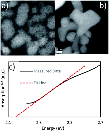 | ||
| Fig. 2 (a) TEM HAADF image of the Cu3PS4 nanoparticles (b) TEM HAADF image of the Cu6PS5Cl nanoparticles UV-Vis absorption data for the Cu3PS4 nanoparticles shows an indirect band gap at 2.15 eV. | ||
From the TEM images of the Cu3PS4 nanoparticles (see Fig. 2a), we can examine their size and shape. We have found them to be about 3–15 nm in diameter and are irregularly shaped. We also examined the plane spacing as well, and found the (002) plane with a d-spacing of 0.30 nm (see ESI†). We did not see any evidence of a phosphorus layer on the outside of the nanoparticles. This is in agreement with the SEM-EDX.
The band gap was measured using UV-Vis spectroscopy (see Fig. 2). After examining the absorption1/2 curve, we found a linear region that corresponded to an indirect transition at 2.15 eV. It compares favourably with the previous work report for this material having an indirect band gap at 2.3 eV.20
Photoluminance data for Cu3PS4 also shows the band gap to be around 2.3 eV, close to our measured band gap for nanoparticles synthesized by an earlier method.23
The state of phosphorus and how it leads to different reaction products
We have found that the state of the phosphorus source is a determining factor for the nanoparticle phase formed. P2S5 reacts with thiols to from thiophosphate esters,38 and these dissolve in the remaining excess thiol. We have observed the dissolution of the P2S5 to occur in 1-dodecanethiol at elevated temperatures, starting around 100 °C and finishing around 165 °C. Based on this and the other findings shown in this contribution we propose the following reaction pathways for the formation of either Cu3PS4 or Cu6PS5Cl (see Fig. 3). Different reaction conditions effected the pathway that the reaction would follow and would have a significant impact on the composition of the reaction products. Knowledge of this reaction scheme was what guided us to developing both pure phase syntheses previously described.To test the significance of the CuCl2 to P2S5 ratio, we first added stoichiometric quantities of CuCl2 and P2S5 (Cu![[thin space (1/6-em)]](https://www.rsc.org/images/entities/char_2009.gif) :
:![[thin space (1/6-em)]](https://www.rsc.org/images/entities/char_2009.gif) P is 3
P is 3![[thin space (1/6-em)]](https://www.rsc.org/images/entities/char_2009.gif) :
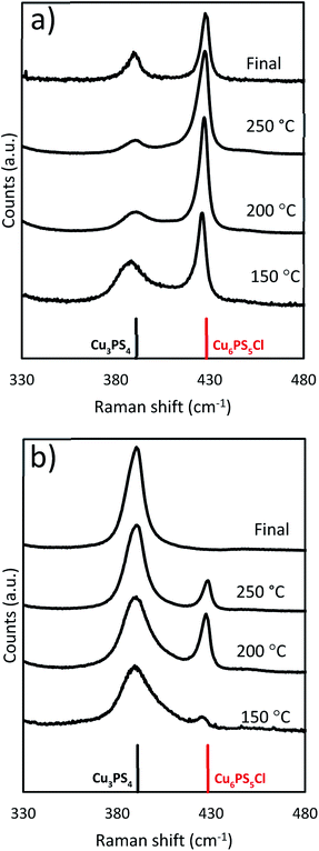
:![[thin space (1/6-em)]](https://www.rsc.org/images/entities/char_2009.gif) 1) to the DDT at room temperature in the flask. This mixture was heated to 250 °C and held there for 1 hour. During heat up, aliquots of samples were collected from the reaction flask and analyzed for composition by Raman spectroscopy, and the results are shown in Fig. 4a. It seems that the reaction of the P2S5 with the CuCl2 and DDT happen concurrently. When we compared the two phases of Cu3PS4 and Cu6PS5Cl nanoparticles present during the heating ramp as well as the final product from the synthesis we saw a shifting composition. As the reaction temperature increased, the Cu6PS5Cl phase began to form in a greater amount than the Cu3PS4. The final composition was a mixture of both phases.
1) to the DDT at room temperature in the flask. This mixture was heated to 250 °C and held there for 1 hour. During heat up, aliquots of samples were collected from the reaction flask and analyzed for composition by Raman spectroscopy, and the results are shown in Fig. 4a. It seems that the reaction of the P2S5 with the CuCl2 and DDT happen concurrently. When we compared the two phases of Cu3PS4 and Cu6PS5Cl nanoparticles present during the heating ramp as well as the final product from the synthesis we saw a shifting composition. As the reaction temperature increased, the Cu6PS5Cl phase began to form in a greater amount than the Cu3PS4. The final composition was a mixture of both phases.
When the reaction is modified so excess amounts of P2S5 are added (Cu![[thin space (1/6-em)]](https://www.rsc.org/images/entities/char_2009.gif) :
:![[thin space (1/6-em)]](https://www.rsc.org/images/entities/char_2009.gif) P was 2
P was 2![[thin space (1/6-em)]](https://www.rsc.org/images/entities/char_2009.gif) :
:![[thin space (1/6-em)]](https://www.rsc.org/images/entities/char_2009.gif) 1) initially at room temperature to the reaction flask, we observed a different end result from the previous stoichiometric case. The beginning of the reaction remained similar with both phases present throughout the reaction period. Although the relative quantity of Cu3PS4 was now higher with respect to Cu6PS5Cl but then end product was not the same (see Fig. 4b). Due to the excess amounts of P2S5 added, all of the Cu6PS5Cl phase converted into the Cu3PS4 phase. We have tested this conversion in a separate reaction by using Cu6PS5Cl as a replacement for the CuCl2 (Cu
1) initially at room temperature to the reaction flask, we observed a different end result from the previous stoichiometric case. The beginning of the reaction remained similar with both phases present throughout the reaction period. Although the relative quantity of Cu3PS4 was now higher with respect to Cu6PS5Cl but then end product was not the same (see Fig. 4b). Due to the excess amounts of P2S5 added, all of the Cu6PS5Cl phase converted into the Cu3PS4 phase. We have tested this conversion in a separate reaction by using Cu6PS5Cl as a replacement for the CuCl2 (Cu![[thin space (1/6-em)]](https://www.rsc.org/images/entities/char_2009.gif) :
:![[thin space (1/6-em)]](https://www.rsc.org/images/entities/char_2009.gif) P 2
P 2![[thin space (1/6-em)]](https://www.rsc.org/images/entities/char_2009.gif) :
:![[thin space (1/6-em)]](https://www.rsc.org/images/entities/char_2009.gif) 1) and observed the phase change to Cu3PS4. This occurs at 250 °C but does not happen at 150 °C. The temperature dependence was why the Cu6PS5Cl phase appears at low temperatures only to disappear at higher temperatures.
1) and observed the phase change to Cu3PS4. This occurs at 250 °C but does not happen at 150 °C. The temperature dependence was why the Cu6PS5Cl phase appears at low temperatures only to disappear at higher temperatures.
To examine the changes that may occur with the state of phosphorus during the reaction, three experiments were done where the CuCl2 was added to P2S5 and DDT mixture at different points in the reaction. While P2S5 was added to DDT at room temperature and heated, the CuCl2 with Cu![[thin space (1/6-em)]](https://www.rsc.org/images/entities/char_2009.gif) :
:![[thin space (1/6-em)]](https://www.rsc.org/images/entities/char_2009.gif) P of 2
P of 2![[thin space (1/6-em)]](https://www.rsc.org/images/entities/char_2009.gif) :
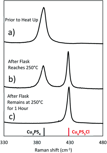
:![[thin space (1/6-em)]](https://www.rsc.org/images/entities/char_2009.gif) 1 was added prior to heating, just after reaching 250 °C, and after 1 hour at 250 °C. The composition of the product nanoparticles shifted from Cu3PS4 rich to Cu6PS5Cl rich as the CuCl2 was added later (see Fig. 5). We suggest that this shift is caused by the reaction history between the P2S5 and the DDT. It seems that after P2S5 is dissolved in DDT, there are two types of phosphorus species that are present in the solution. The first type reacts with Cu-species to directly form Cu3PS4 while the second type reacts to form Cu6PS5Cl. At a high temperature of 250 °C, the first type of phosphorus species further reacts with Cu6PS5Cl to form Cu3PS4. While in this study we have not delineated each type of phosphorus species, it is likely that the first type of phosphorus species are simply dissolved P2S5 molecules in DDT (we denote it
1 was added prior to heating, just after reaching 250 °C, and after 1 hour at 250 °C. The composition of the product nanoparticles shifted from Cu3PS4 rich to Cu6PS5Cl rich as the CuCl2 was added later (see Fig. 5). We suggest that this shift is caused by the reaction history between the P2S5 and the DDT. It seems that after P2S5 is dissolved in DDT, there are two types of phosphorus species that are present in the solution. The first type reacts with Cu-species to directly form Cu3PS4 while the second type reacts to form Cu6PS5Cl. At a high temperature of 250 °C, the first type of phosphorus species further reacts with Cu6PS5Cl to form Cu3PS4. While in this study we have not delineated each type of phosphorus species, it is likely that the first type of phosphorus species are simply dissolved P2S5 molecules in DDT (we denote it  in Fig. 3), and the second type of phosphorus species are by-products of P2S5 reaction with DDT such as (RS)3PS and (RS)2PSSH. An increase in the second type of phosphorus species seems to occur with reaction time at 250 °C leading to favorable formation of Cu6PS5Cl over Cu3PS4. In another possibility, the reaction of P2S5 with DDT may itself provide the two types of phosphorus species.
To isolate the injection process as a possible variable, the synthesis was repeated with DDT heated alone to 250 °C and then injected CuCl2 and P2S5 (Cu![[thin space (1/6-em)]](https://www.rsc.org/images/entities/char_2009.gif) :
:![[thin space (1/6-em)]](https://www.rsc.org/images/entities/char_2009.gif) P of 2
P of 2![[thin space (1/6-em)]](https://www.rsc.org/images/entities/char_2009.gif) :
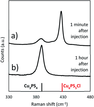
:![[thin space (1/6-em)]](https://www.rsc.org/images/entities/char_2009.gif) 1) powders together at 250 °C. As with the solvothermal reaction in Fig. 4b a time dependent evolution of the composition is seen. The composition shifts from initially being Cu6PS5Cl rich to only Cu3PS4 over the hour long reaction (see Fig. 6). This demonstrates that when the CuCl2 and the P2S5 are added together either at room temperature or at 250 °C, the reaction will eventually produce Cu3PS4 free of Cu6PS5Cl. However it is interesting to compare initial reaction products in Fig. 4b) at a lower temperature of 150 °C with that in Fig. 6 after 1 minute of injection. We find that while at lower temperatures Cu3PS4 is favored, at a high temperature of 250 °C Cu6PS5Cl is initially favored. It seems at the temperature of 250 °C, not only the second type of phosphorus species is quick to form but its kinetic rate to form Cu6PS5Cl is much higher than corresponding rate with the first type of phosphorus species to form Cu3PS4. With co-injection of P2S5 and CuCl2 at 250 °C, we have enough first type of phosphorus species to eventually convert all the Cu6PS5Cl to Cu3PS4.
1) powders together at 250 °C. As with the solvothermal reaction in Fig. 4b a time dependent evolution of the composition is seen. The composition shifts from initially being Cu6PS5Cl rich to only Cu3PS4 over the hour long reaction (see Fig. 6). This demonstrates that when the CuCl2 and the P2S5 are added together either at room temperature or at 250 °C, the reaction will eventually produce Cu3PS4 free of Cu6PS5Cl. However it is interesting to compare initial reaction products in Fig. 4b) at a lower temperature of 150 °C with that in Fig. 6 after 1 minute of injection. We find that while at lower temperatures Cu3PS4 is favored, at a high temperature of 250 °C Cu6PS5Cl is initially favored. It seems at the temperature of 250 °C, not only the second type of phosphorus species is quick to form but its kinetic rate to form Cu6PS5Cl is much higher than corresponding rate with the first type of phosphorus species to form Cu3PS4. With co-injection of P2S5 and CuCl2 at 250 °C, we have enough first type of phosphorus species to eventually convert all the Cu6PS5Cl to Cu3PS4.
The conversion of Cu6PS5Cl to Cu3PS4
To see if the Cu6PS5Cl could directly be converted to Cu3PS4, a series of reactions was performed using Cu6PS5Cl as the only copper source. These reactions were done under three different conditions. Two that used the solvothermal method, whereby Cu6PS5Cl and P2S5 are added to DDT at room temperature and the mixture is heated to the reaction temperature of either 150 °C or 250 °C (Fig. 7b and a respectively). In the third experiment, the Cu6PS5Cl is added after the P2S5 has been heated in DDT for 1 hour at 250 °C (Fig. 7c). The Cu6PS5Cl![[thin space (1/6-em)]](https://www.rsc.org/images/entities/char_2009.gif) :
:![[thin space (1/6-em)]](https://www.rsc.org/images/entities/char_2009.gif) P2S5 in all three experiments was 2
P2S5 in all three experiments was 2![[thin space (1/6-em)]](https://www.rsc.org/images/entities/char_2009.gif) :
:![[thin space (1/6-em)]](https://www.rsc.org/images/entities/char_2009.gif) 3 which is close to the Cu
3 which is close to the Cu![[thin space (1/6-em)]](https://www.rsc.org/images/entities/char_2009.gif) :
:![[thin space (1/6-em)]](https://www.rsc.org/images/entities/char_2009.gif) P ratio of 2
P ratio of 2![[thin space (1/6-em)]](https://www.rsc.org/images/entities/char_2009.gif) :
:![[thin space (1/6-em)]](https://www.rsc.org/images/entities/char_2009.gif) 1 used in earlier experiments. For the solvothermal reactions, there was significant conversion at 250 °C but very little if any at 150 °C (see Fig. 7). This shows that the rate of reaction between the first type of phosphorus species and Cu6PS5Cl to form Cu3PS4 at lower temperatures (≤150 °C) is quite slower and one needs higher temperatures for this reaction rate to become appreciable. This temperature dependence on the conversion is the reason that in our Cu3PS4 synthesis shown in Fig. 4b), Cu6PS5Cl is present during early stages of the reaction at lower temperatures and only converts to Cu3PS4 later on after the reaction has reached 250 °C. When the P2S5 was reacted for an hour with the DDT at 250 °C prior to adding the Cu6PS5Cl, the conversion to Cu3PS4 was stopped. This is consistent with the possibility that at 250 °C with time there is a decrease in the amount of the first type of phosphorus species and after one hour, the predominant phosphorus species is the second type which does not lead to the formation of Cu3PS4. This is consistent with our Cu6PS5Cl nanoparticle synthesis recipe where P2S5 is first heated at 250 °C in DDT for an hour, the mixture is then cooled to room temperature to add CuCl2 and run the solvothermal synthesis of the nanoparticles.
1 used in earlier experiments. For the solvothermal reactions, there was significant conversion at 250 °C but very little if any at 150 °C (see Fig. 7). This shows that the rate of reaction between the first type of phosphorus species and Cu6PS5Cl to form Cu3PS4 at lower temperatures (≤150 °C) is quite slower and one needs higher temperatures for this reaction rate to become appreciable. This temperature dependence on the conversion is the reason that in our Cu3PS4 synthesis shown in Fig. 4b), Cu6PS5Cl is present during early stages of the reaction at lower temperatures and only converts to Cu3PS4 later on after the reaction has reached 250 °C. When the P2S5 was reacted for an hour with the DDT at 250 °C prior to adding the Cu6PS5Cl, the conversion to Cu3PS4 was stopped. This is consistent with the possibility that at 250 °C with time there is a decrease in the amount of the first type of phosphorus species and after one hour, the predominant phosphorus species is the second type which does not lead to the formation of Cu3PS4. This is consistent with our Cu6PS5Cl nanoparticle synthesis recipe where P2S5 is first heated at 250 °C in DDT for an hour, the mixture is then cooled to room temperature to add CuCl2 and run the solvothermal synthesis of the nanoparticles.
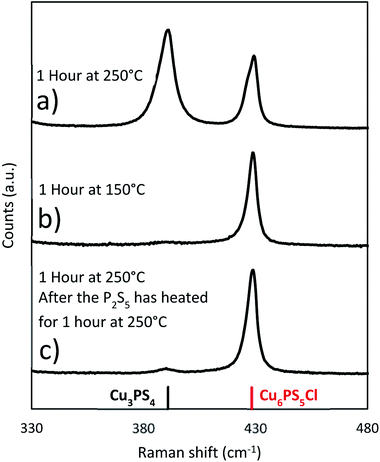 | ||
Fig. 7 Raman spectra from reactions where Cu6PS5Cl is used as the copper source in place of CuCl2. The Cu6PS5Cl is added at room temperature unless otherwise noted. (Cu6PS5Cl![[thin space (1/6-em)]](https://www.rsc.org/images/entities/char_2009.gif) : :![[thin space (1/6-em)]](https://www.rsc.org/images/entities/char_2009.gif) P2S5 2 P2S5 2![[thin space (1/6-em)]](https://www.rsc.org/images/entities/char_2009.gif) : :![[thin space (1/6-em)]](https://www.rsc.org/images/entities/char_2009.gif) 3). 3). | ||
When the original reaction conditions are used (using CuCl2 and P2S5 added together at room temperature to DDT and then heating to reaction temperature and holding for 1 hour) but using temperatures lower than 250 °C, we did not get the desired single phase product (see Fig. 8). We observed similar compositions during the temperature ramp to the previously discussed reactions, where there was a mixture of the Cu3PS4 and Cu6PS5Cl phases, when the temperature is below 250 °C (Fig. 4b). This was consistent with our findings on the effect of temperature on the conversion from Cu6PS5Cl to Cu3PS4 and the postulate that there are two types of phosphorus species in the solution with different reaction rates. At lower temperatures, reaction rate between first type of phosphorus species and Cu6PS5Cl is low and therefore, one sees a preference for more Cu3PS4 as the temperature increases.
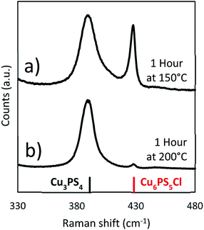 | ||
Fig. 8 Raman spectra from solvothermal syntheses at lower temperatures (Cu![[thin space (1/6-em)]](https://www.rsc.org/images/entities/char_2009.gif) : :![[thin space (1/6-em)]](https://www.rsc.org/images/entities/char_2009.gif) P 2 P 2![[thin space (1/6-em)]](https://www.rsc.org/images/entities/char_2009.gif) : :![[thin space (1/6-em)]](https://www.rsc.org/images/entities/char_2009.gif) 1) (a) 150 °C and (b) 200 °C. 1) (a) 150 °C and (b) 200 °C. | ||
Conclusions
Understanding and being able to control the process of the phase change was the important step to achieving each single phase product of Cu3PS4 and Cu6PS5Cl. High temperatures facilitate the conversion, but it is necessary to add excess P2S5 to make sure there is enough phosphorus to complete it. The conversion to Cu3PS4 can be completely stopped if the phosphorus is dissolved in the thiol at high temperature of 250 °C before adding the copper, because in this state it will not react with the Cu6PS5Cl.In order to explain the experimental observations and tailor the reaction when P2S5 and CuCl2 are reacted in DDT, we invoke the presence of two types of phosphorus species in the solution. The first type of phosphorus species is favoured when excess phosphorus is added to the solution and solution temperatures are low. This first type of phosphorus species reacts directly with copper precursors in the solution to for Cu3PS4, and also with Cu6PS5Cl to form Cu3PS4. Although for the reaction rates to be meaningful with Cu6PS5Cl, higher temperatures (T ∼ 250 °C) are needed. The second type of phosphorus species exclusively reacts with copper precursors in the solution to Cu6PS5Cl, and the abundance of this phosphorus species increases as temperature of the reaction is increased. At T ∼ 250 °C, after a period of about one hour, all of the phosphorus seems to be present as the second type of phosphorus species. It is likely that when P2S5 is added to DDT and heated, initial phosphorus species are of the first type which eventually convert to the second type at the higher temperatures. Once the second type of phosphorus species is present in the solution, it reacts rapidly with copper to form Cu6PS5Cl. However, if reaction temperatures are high enough and first type of phosphorus is present in the solution, Cu6PS5Cl will react to form Cu3PS4. It is likely that the first type of phosphorus is a dissolved P2S5 in DDT and the second type of phosphorus species is likely to be formed due to a reaction between P2S5 and DDT. Although the possibility of each phosphorus specie to be different by-product of the reaction between P2S5 and DDT cannot be ruled out.
Key to producing pure phase Cu3PS4 is to ensure the presence of the first type of phosphorous specie and the reaction temperature to be high enough for the conversion of any by-product Cu6PS5Cl to Cu3PS4. A reaction temperature of 250 °C with co-injection of P2S5 and CuCl2 fulfils this condition. It insures that all the by-product Cu6PS5Cl is converted to Cu3PS4 before the first type of phosphorus species disappears from the solution phase (by perhaps conversion to the second type of phosphorus species). Similarly, pure phase synthesis of Cu6PS5Cl requires the absence of the first type of phosphorus species from the solution phase. This is achieved by preheating the P2S5 with DDT at 250 °C for one hour. This ensures that there is little of the first type of phosphorus species in the solution phase. Addition of CuCl2 to this solution results in exclusively in the formation of Cu6PS5Cl.
In summary, we have shown a new synthesis method for synthesizing copper phosphorus sulfide nanoparticles. Our new synthesis is only a single step reaction that produces a phase pure product, making it advantageous to previous methods that have used multiple reactions and lead to a multiphase product. We have determined that controlling the reaction of the phosphorus pentasulfide with the solvent is the key to determining the phase of the final product. We have tested this using different reaction conditions. These nanoparticles are expected to have applications as a precursor for solar absorber films and other thin-film electronic devices.
Statement of data access
The data associated with this manuscript can be found at the project's website: https://datacenterhub.org/groups/dmref1534691.Conflicts of interest
There are no conflicts to declare.Acknowledgements
The authors would like to acknowledge support from NSF grant #1534691-DMR (DMREF: Rabid Design of Earth Abundant Inorganic Materials for Future PVs). The authors would like to thank Caleb Miskin and Xianyi Hu for their assistance with TEM images. The authors would also like to thank Brookhaven National Laboratory for their assistance with the TEM images. The authors like to thank Scott McClary, Joseph Andler, and Caleb Miskin for their helpful discussions.References
- S. M. Mcleod, C. J. Hages, N. J. Carter and R. Agrawal, Prog. Photovoltaics, 2015, 23, 1550–1556 CAS.
- P. Jackson, R. Wuerz, D. Hariskos, E. Lotter, W. Witte and M. Powalla, Phys. Status Solidi RRL, 2016, 10, 583–586 CrossRef CAS.
- T. Todorov, T. Gershon, O. Gunawan, Y. S. Lee, C. Sturdevant, L. Y. Chang and S. Guha, Adv. Energy Mater., 2015, 5, 1–6 Search PubMed.
- D. Keller, S. Buecheler, P. Reinhard, F. Pianezzi, B. Bissig, R. Carron, F. Hage, Q. Ramasse, R. Erni and A. N. Tiwari, Appl. Phys. Lett., 2016, 109(15), 152103 CrossRef.
- R. L. Garris, L. M. Mansfield, B. Egaas and K. Ramanathan, IEEE J Photovolt., 2016, 7, 281–285 Search PubMed.
- D. Kuciauskas, P. Dippo, Z. Zhao, L. Cheng, A. Kanevce, W. K. Metzger and M. Gloeckler, IEEE J Photovolt., 2016, 6, 313–318 Search PubMed.
- R. W. Crisp, M. G. Panthani, W. L. Rance, J. N. Duenow, P. a Parilla, R. Callahan, M. S. Dabney, J. J. Berry, D. V Talapin and J. M. Luther, ACS Nano, 2014, 8, 9063–9072 CrossRef CAS PubMed.
- D. E. Swanson, J. R. Sites and W. S. Sampath, Sol. Energy Mater. Sol. Cells, 2017, 159, 389–394 CrossRef CAS.
- C. K. Miskin, W.-C. Yang, C. J. Hages, N. J. Carter, C. S. Joglekar, E. A. Stach and R. Agrawal, Prog. Photovoltaics, 2015, 23, 654–659 CAS.
- W. Wang, M. T. Winkler, O. Gunawan, T. Gokmen, T. K. Todorov, Y. Zhu and D. B. Mitzi, Adv. Energy Mater., 2014, 4, 1301465 CrossRef.
- K. Rudisch, Y. Ren, C. Platzer-Björkman and J. Scragg, Appl. Phys. Lett., 2016, 108(23), 231902 CrossRef.
- T. Mise, S. Tajima, T. Fukano, K. Higuchi, T. Washio, K. Jimbo and H. Katagiri, Prog. Photovoltaics, 2016, 24, 1009–1015 CAS.
- T. Matsui, H. Sai, K. Saito and M. Kondo, Prog. Photovoltaics, 2013, 21, 1363–1369 CAS.
- C. J. Hages, N. J. Carter and R. Agrawal, J. Appl. Phys., 2016, 119(1), 014505 CrossRef.
- T. Gokmen, O. Gunawan, T. K. Todorov and D. B. Mitzi, Appl. Phys. Lett., 2013, 103(10), 103506 CrossRef.
- C. J. Hages, N. J. Carter, R. Agrawal and T. Unold, J. Appl. Phys., 2014, 115(23), 234504 CrossRef.
- J. E. Moore, C. J. Hages, R. Agrawal, M. S. Lundstrom and J. L. Gray, Appl. Phys. Lett., 2016, 109, 1–5 CrossRef.
- F. Hong, W. Lin, W. Meng and Y. Yan, Phys. Chem. Chem. Phys., 2016, 18, 4828–4834 RSC.
- K. Biswas, S. Lany and A. Zunger, Appl. Phys. Lett., 2010, 96, 1–4 Search PubMed.
- J. V. Marzik, a. K. Hsieh, K. Dwight and a. Wold, J. Solid State Chem., 1983, 49, 43–50 CrossRef CAS.
- R. B. Balow, E. J. Sheets, M. M. Abu-omar and R. Agrawal, Chem. Mater., 2015, 27, 2290–2293 CrossRef CAS.
- V. Itthibenchapong, R. S. Kokenyesi, A. J. Ritenour, L. Zakharov, S. Boettcher, J. Wager and D. Keszler, J. Mater. Chem. C, 2013, 657–662 RSC.
- E. J. Sheets, W.-C. Yang, R. B. Balow, Y. Wang, B. C. Walker, E. A. Stach and R. Agrawal, J. Mater. Res., 2015, 30, 3710–3716 CrossRef CAS.
- L. Yu, R. S. Kokenyesi, D. A. Keszler and A. Zunger, Adv. Energy Mater., 2013, 3, 43–48 CrossRef CAS.
- I. Repins, N. Vora, C. Beall, S.-H. Wei, Y. Yan, M. Romero, G. Teeter, H. Du, B. To, M. Young and R. Noufi, Mater. Res. Soc. Symp. Proc., 2011, 1324, 97–108 CrossRef.
- T. Shi, W. Yin, M. Al-jassim, Y. Yan, T. Shi, W. Yin, M. Al-jassim and Y. Yan, Appl. Phys. Lett., 2013, 103(15), 152105 CrossRef.
- M. Schulte-Kellinghaus and V. Krämer, Thermochim. Acta, 1978, 27, 141–149 CrossRef CAS.
- R. B. Balow, C. K. Miskin, M. M. Abu-Omar and R. Agrawal, Chem. Mater., 2017, 29, 573–578 CrossRef CAS.
- R. Nitsche and P. Wild, Mater. Res. Bull., 1970, 5, 419–423 CrossRef CAS.
- D. H. Foster, V. Jieratum, R. Kykyneshi, D. a. Keszler and G. Schneider, Appl. Phys. Lett., 2011, 99, 181903 CrossRef.
- B. K. Graeser, C. J. Hages, W. C. Yang, N. J. Carter, C. K. Miskin, E. A. Stach and R. Agrawal, Chem. Mater., 2014, 26, 4060–4063 CrossRef CAS.
- S. A. McClary, J. Andler, C. A. Handwerker and R. Agrawal, J. Mater. Chem. C, 2017, 5, 6913–6916 RSC.
- M. Chen and S. Adams, J. Solid State Electrochem., 2015, 19, 697–702 CrossRef CAS.
- W. F. Kuhs, R. Nitsche and K. Scheunemann, Acta Crystallogr., Sect. B: Struct. Crystallogr. Cryst. Chem., 1978, 34, 64–70 CrossRef.
- I. P. Studenyak, M. Kranjcec, R. Y. Buchuk, V. O. Stephanovich and S. Kokenyesi, Semicond. Phys., Quantum Electron. Optoelectron., 2013, 16, 259–264 CrossRef CAS.
- W. F. Kuhs, R. Nitsche and K. Scheunemann, Mater. Res. Bull., 1979, 14, 241–248 CrossRef CAS.
- A. Gagor, A. Pietraszko and D. Kaynts, J. Solid State Chem., 2008, 181, 777–782 CrossRef CAS.
- L. Maier and J. R. Van Wazer, J. Am. Chem. Soc., 1962, 84, 3054–3058 CrossRef CAS.
Footnote |
| † Electronic supplementary information (ESI) available. See DOI: 10.1039/c8ra06241b |
| This journal is © The Royal Society of Chemistry 2018 |


