 Open Access Article
Thermal tuning of graphene-embedded waveguide filters based on the polymer–silica hybrid structure
Yue Cao,
Baizhu Lin,
Yue Sun,
Xinchi Che,
Yunji Yi *,
Fei Wang and
Daming Zhang
State Key Laboratory of Integrated Optoelectronics, College of Electronic Science & Engineering, Jilin University, Changchun 130012, P. R. China. E-mail: yiyj@jlu.edu.cn
First published on 31st August 2018
Abstract
Graphene-embedded waveguide filters have been widely used in the areas of polarization and mode filtering because of their characteristics of easy fabrication, high integration, and high extinction ratio. In this article, we propose thermal tuning filters based on a graphene-embedded polymer–silica hybrid waveguide. Compared to previously reported filters, this device can realize the efficient adjustment of the relative position between the optical field and graphene layer by thermal tuning. Consequently, the polarization and mode filtering properties of the filter can be adjusted by thermal tuning. This high-efficiency tuning characteristic is due to the opposite thermo-optic coefficient of the polymer and silica material. Furthermore, a layer with a low refractive index is embedded in the polymer–silica hybrid core to increase the tuning efficiency. The optical absorption, mode properties, and thermal field distributions were simulated. It was found that such single-mode filters could realize Ex11-pass or Ex11-stop selection, and the attenuation variation (Δα) was optimized to 32.20 dB cm−1 (Ex11 mode) using the top electrode and air trench structure with ΔT = 10 K and P = 48.39 mW in the single-mode waveguide. For the multimode waveguide filters, the attenuation variation (Δα) of the Exmn modes (Ex11, Ex12, and Ex21) was also calculated. Such thermal tuning filters were found to be compatible with chemical potential regulation graphene modulators and filters, and they can be applied to broadband photonic integrated circuits and mode division multiplexing systems.
Introduction
Graphene, a two-dimensional honeycomb lattice with a flat monolayer structure of carbon atoms, exhibits exceptional optical properties such as tunable absorption, saturable absorption, efficient luminescence, and exceptional nonlinearity.1,2 Various functional photonic devices based on graphene, such as mode filters,3 modulators,1,4–6 photodetectors7,8 and sensors9 have been proposed.Mode filters separating light with different polarizations are fundamental components because a fixed optical waveguide usually works under only one particular polarization state. Traditional mode filters are mainly polarizing beam-splitting prisms based on the birefringence effect of natural crystals10 and waveguide mode filters.11,12 Compared to traditional mode filters, graphene film-integrated optical waveguide filters possess high extinction ratios and broadband properties because of the excellent optical absorption effects of graphene, which can alternatively serve as transverse magnetic (TM)-pass or transverse electric (TE)-pass filters. Thus, graphene-based mode filters (GBMFs) have been used in devices such as mode filters and broadband mode division multiplexing (MDM) transmission systems.13
According to devices using this material, several GBMFs have recently been proposed including inorganic GBMFs, polymer GBMFs, and silica–polymer hybrid GBMFs. Cheng et al. presented a graphene-on-silicon waveguide and achieved a 7.7 dB attenuation for the TM mode.14 A polymer mode extinction filter with air cladding obtained an attenuation of 20.7 dB for TM-polarized light.15 In addition, a broadband graphene/glass hybrid waveguide with PMMA cladding achieved an extinction ratio of 27 dB for TM-polarized light.16 These GBMFs can realize the attenuation of only one polarization state of the base mode in the waveguide with high extinction ratio properties. However, the hybrid structure has not made full use of the advantages of the hybrid integration.
In addition, according to the change in the chemical potential of graphene, GBMFs are divided into electro-optic GBMFs and non-electro-optic GBMFs. For graphene electro-absorption modulator on silicon, a graphene absorption loss of 0.11 dB μm−1 and 0.06 dB μm−1 were extracted for the TM and TE modes respectively.17 Non-electro-optic GBMFs with two graphene layers sandwiched between Si3N4 and silicon layers achieved an extinction ratio higher than 40 dB.15 The devices reported above have achieved high extinction ratios for the base mode of the waveguide. However, polarization states of GBMFs between TE-pass and TM-pass cannot be switched by changing the chemical potential. Thus, it has been proposed that the polarization states are attributed to waveguide parameters such as the device dimension and refractive index. Thus, different structures of non-electro-optic GBMFs are shown to be essential for the development of mode filters.18
Moreover, in the area of MDM, a mode filter reportedly embedded in different positions and lengths of graphene in the waveguide core realized the attenuation of different modes in a multimode waveguide. This mode filter with a graphene layer placed at the center of the waveguide core realizes the attenuation of the Ex11 mode and Ex21 mode. When the graphene film is placed at the location where the Ex13 mode is zero, the filter realizes the attenuation of the Ex11, Ex21, and Ex12 modes. In addition, when a narrow graphene film is placed at the center of the waveguide core, the filter attenuates the Ex11 mode.3 However, fixed graphene-based waveguide structures have fixed mode attenuation characteristics.
In this paper, a thermal tuning filter based on a graphene-embedded polymer–silica hybrid waveguide is presented. The position of the light field of this filter structure can be regulated by varying the electrode temperature. Meanwhile, the relative position between the graphene and optical field can be regulated, which results in the change in the absorption of different modes. Because of the opposite thermo-optic coefficient of the polymer and silica material, the optical field can be regulated with a high efficiency. Two structures of the optimized thermal tuning hybrid filters with high extinction ratios have been obtained with a top electrode and side electrodes.
Design and simulation
Our proposed filters are based on the concept of embedding a graphene layer in a waveguide to generate strong absorption of the tangential electric field, E‖, which is dominantly composed of the Ex direction for Exmn modes and Ez direction for Eymn modes. The Exmn and Eymn modes denote the x and y directions of the major electric-field component, respectively, and m and n denote the numbers of peaks in the major electric-field distribution. We designed a graphene layer embedded in a polymer core waveguide, which adheres to a silica waveguide. The isotropic model of the graphene was used in the simulation for Exmn modes.19 Before thermal tuning, the center position of the Ex11-mode light field was designed to be located in the graphene layer. At this position, the graphene exhibits the maximum light–graphene interaction with the Ex11 mode. While the graphene layer should not induce much loss to the Eymn modes. Also, the polymer–silica vertical hybrid waveguide we designed will ensure the best tuning effect because of the opposite thermo-optic coefficient of the polymer and inorganic material. If we raise the working temperature, the refractive index of the polymer should decrease while the silica will increase, leading to a change in the distribution of the light field of the Exmn polarization state. The redistribution of the Exmn optical fields will realize mode attenuation in the single-mode waveguide and multimode waveguide, respectively. For the heating electrode structure of the top electrode and side electrode, the top electrode with an air trench structure (structure 1) was designed to realize Ex11 mode attenuation and the Ey11-pass waveguide. In addition, the side electrode structure (structure 2) was designed to take advantage of the high thermal conductivity of graphene to reduce the power consumption.20Device structure and theoretical analysis
The absorption of the light in waveguide is mainly related to the imaginary part of the refractive index of graphene. The graphene effective permittivity εg (=ng2) can be calculated from the conductivity σ:
 | (1) |
The graphene conductivity σ is affected by the temperature, graphene electronic relaxation time, optical angular frequency, and graphene Fermi level. The parameters of graphene conductivity, including intraband conductivity and interband conductivity, can be calculated using the Kubo formalism:
| σ = σintra + σinter, | (2) |
 | (3) |
Device structure 1 (top electrode structure with an air trench) and structure 2 (side electrode structure without air trench) in the three-dimension and cross-sectional directions are illustrated in Fig. 1. The device consists of a silica substrate, polymer cladding, polymer–silica hybrid core layer, graphene strip embedded in the polymer material, and sheet layer with a low refractive index embedded between the hybrid waveguide core. The dimensions of the polymer–silica hybrid layer are a = b = 6 μm. The parameters de = 0.1 μm, dg = 0.00034 μm, and dp = 0.1 μm indicate the thickness of the electrode, graphene layer, and sheet layer, respectively. n1 = 1.467, n2 = 1.466, and n4 = 1.455 are the refractive indices of the polymer layer, silica layer, and silica cladding layer, respectively. The height of the polymer waveguide h and the refractive index of polymer cladding n3 are variables to adjust the position of the light field in the waveguide. The calculated imaginary and real part of the refractive index is 2.79 and 2.97 respectively.
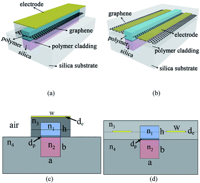 | ||
| Fig. 1 Three-dimensional structures and two-dimensional cross-sectional structures of polymer–graphene–silica hybrid waveguide with structure (a and c) 1 and (b and d) 2, respectively. | ||
Thermal field simulation
The position of the electrode will influence the heating efficiency of the polymer–silica hybrid waveguide. Fig. 2 presents the thermal field distribution of the top electrode with w = 10 μm (an air trench is etched to increase the electrode heating efficiency) and side electrode structure with w = 6 μm. The temperature of the central polymer layer is 297.26 K (structure 1) and 300.28 K (structure 2), which indicates that the side electrode structure has a higher heating efficiency than the top electrode structure.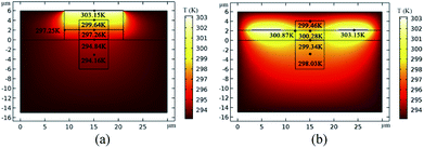 | ||
| Fig. 2 Thermal field distribution for (a) top electrode structure with w = 10 μm and (b) side electrode structure with w = 6 μm. | ||
Single-mode simulation
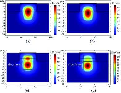
In order to realize a low-power-consumption device, a sheet (dp = 0.1 μm) with a low refractive index was embedded in the hybrid waveguide, which is a benefit for the light field moving away from the graphene layer, reducing the graphene absorption in the hybrid waveguide. The imaginary part of the effective refractive index has been calculated by COMSOL with a wavelength of 1550 nm. The thermo-optical coefficients of polymer and silica are −3.0 × 10⁻⁴ and 1.28 × 10⁻⁵ respectively.21Without the sheet layer, the optical field distribution of the hybrid waveguide with electrode temperatures of 293.15 and 303.15 K is presented in Fig. 3(a) and (b), respectively. The simulated light absorption is 94.78 and 67.15 dB cm−1 at electrode temperatures of 293.18 and 303.15 K, respectively, and the Ex11-polarized light still cannot pass through the waveguide when the heating electrode increases by 10 K with electrode heating power (P) of 48.39 mW.22
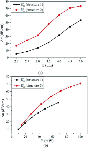
By varying the height of the polymer material layer and the refractive index of the polymer cladding, a single-mode waveguide was obtained. With a sheet layer embedded in the hybrid waveguide, Fig. 3(c) and (d) present the light field distribution at temperatures of 293.15 and 303.15 K, respectively (structure 1). The light field distribution and attenuation of Ex11 mode as a function of h with electrode temperature of 293.15 K and 303.15 K for structure 1 are shown in Fig. 4(a). From the light field distribution, the graphene layer exhibits a significant interaction with the Ex11 mode in the x-direction at the temperature of 293.15 K (Ex11-stop waveguides). When the electrode heating power increases by 48.39 mW, the light field distribution is more concentrated in the silica layer, reducing the interaction between graphene and the Ex11 modes (Ex11-pass waveguides). Thus, it is a benefit for increasing the attenuation of the Ex11 mode at 293.15 K if the height of the polymer layer increases. However, it will also increase the light absorption of the graphene layer at 303.15 K. For example, the attenuation of the Ex11 mode increases to 47.12 dB cm−1 at an electrode temperature of 303.15 K, which cannot realize the Ex11-pass waveguide.
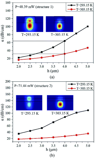 | ||
| Fig. 4 Light field distribution and attenuation of Ex11 mode with different height of polymer layer and electrode temperature (n3 = 1.460) for (a) structure 1 and (b) structure 2, respectively. | ||
Fig. 4(b) presents the light field distribution and the attenuation curves with h = 4 μm, n3 = 1.460 and P = 71.44 mW for structure 2. Because of polarized light effect by the surface plasmon polaritons (SPPs) of the side electrode placed on the graphene layer, the attenuation of the Ex11 mode increases by 23.85 dB cm−1, compared to structure 1 at 293.15 K.
Based on the above discussion, the attenuation variation (Δα = αT(303.15 K) − αT(293.15 K)) has been calculated with h = 4 μm and n3 = 1.460, as shown in Fig. 5. For structure 1, the Δα of the Ex11 mode is 32.30 dB cm−1, realizing the regulation of the Ex11 mode by heating the electrode. For structure 2, the Δα of the Ex11 mode increases up to 61.06 dB cm−1, realizing the efficient regulation of the Ex11 mode waveguide by heating the side electrode. This can be contributed to the effect of the electrode SPPs and the large heating efficiency (discussed later in the article) for the side electrode structure. Fig. 5(b) illustrates the Ex11 mode in structure 1 and structure 2 with different electrode heating power. It is indicated that the device is sensitive to the change in electrode temperature.
Multimode simulation
By increasing the height of the polymer layer or decreasing the refractive index of the polymer cladding, a hybrid multimode waveguide can be obtained. Fig. 6 depicts the relationships between the cladding refractive index and α of the multimode waveguide (Ex11, Ex12 and Ex21 modes) at T = 293.15 K and T = 303.15 K (h = 5 μm and P = 43.86 mW) for device structure 1. When the electrode temperature increases by 10 K, the Ex11-stop waveguide, Ex12-stop waveguide and Ex21-pass waveguide have been realized. When T = 303.15 K, the Ex11-pass waveguide, Ex12-stop waveguide and Ex21-pass waveguide have been realized.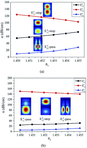 | ||
| Fig. 6 Light field distribution and the attenuation of Ex11 mode, Ex12 mode and Ex21 mode with different polymer cladding n3 (h = 5 μm) at (a) T = 293.15 K and (b) T = 303.15 K. | ||
Fig. 7 shows the attenuation variation (Δα) of Ex11, Ex12, and Ex21 modes as function of cladding refractive index for structure 1 (h = 5 μm; P = 43.86 mW). The regulation of the modes can also be calculated with the attenuation variation (Δα) from 35.70 to 47.84 dB cm−1 (Ex11 mode), from 42.89 to −30.47 dB cm−1 (Ex12 mode), from 4.42 to 18.45 dB cm−1 (Ex21 mode). The optical transmission states (mode-pass or mode-stop) of the multimode-polarized light depend on the device dimension and refractive index. Thus, the optical transmission state for the same polarized light may change with different cladding refractive indices and device dimensions.
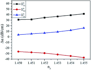 | ||
| Fig. 7 Relationships between cladding refractive index (n3) and attenuation variation (Δα) of Ex11, Ex12, and Ex21 modes (h = 5 μm; P = 43.86 mW; structure 1). | ||
We expect that the multimode-polarized light can be adjusted with different conditions of the refractive index by the heating electrode, realizing multimode thermal tuning filters. However, because the multimode-polarized light is affected significantly by SPPs of the side electrode structure, the transmission state in structure 2 is more complex than that of structure 1 with different device dimensions and refractive indices, which doesn't benefit the adjustment of the multimode-polarized light by changing the temperature of the side electrode.
Conclusions
In summary, we have presented ultra-broadband thermal tuning filters based on a graphene embedded polymer–silica hybrid waveguide. This device can realize the efficient adjustment of the relative position between the optical field and graphene layer by thermal tuning. For a single-mode waveguide, we achieved the regulation of the Ex11 mode with Δα = 32.20 dB cm−1 and the Ex11-pass waveguide for structure 1. We also obtained low-power-consumption devices with a high Δα of 61.06 dB cm−1 (Ex11 mode) for structure 2 in the single-mode waveguide (ΔT = 10 K). Moreover, the side electrode structure had a higher heating efficiency than the top electrode structure. For the multimode waveguide in structure 1, the multimode-polarized light can be regulated by increasing the electrode temperature. The regulation of the modes was analyzed with the attenuation variation (Δα) from 35.70 to 47.84 dB cm−1 (Ex11 mode), from −42.89 to −30.47 dB cm−1 (Ex12 mode), from 4.42 to 18.45 dB cm−1 (Ex21 mode). However, the power consumption is restricted by single-layer graphene structure and large device dimension because of the photolithographic process. The graphene-based filter with a top electrode and air trench structure (structure 1) can be applied to many photonic devices such as thermo-optical switches, MDM systems, and variable optical attenuators. In addition, the graphene-based filter with a side electrode and without an air trench structure (structure 2) has the potential for compatibility with thermo-optical devices and electro-optic devices.Funding
National Natural Science Foundation of China (NSFC) (61605057, 61475061, 61575076); Jilin Provincial Industrial Innovation Special Fund Project (2016C019); Excellent Youth Foundation of Jilin Province (20170520158JH).Conflicts of interest
There are no conflicts to declare.References
- S. J. Koester and M. Li, High-speed waveguide-coupled graphene-on-graphene optical modulators, Appl. Phys., 2012, 100, 171107 Search PubMed.
- Q. Jin, X. B. Li, J. F. Chen and S. M. Gao, Ultra-broadband nonlinearity enhancement based on a novel graphene-silicon hybrid waveguide: Structure design and theoretical analysis, Sci. Rep., 2017, 7, 12290 CrossRef PubMed.
- Z. Chang and K. S. Chiang, Ultra-broadband mode filters based on graphene-embedded waveguides, Opt. Lett., 2017, 42, 3868–3871 CrossRef PubMed.
- M. Liu, X. B. Yin, E. Ulin-Avila, B. S. Geng, T. Zentgraf, L. Ju, F. Wang and X. Zhang, A graphene-based broadband optical modulator, Nature, 2011, 474, 64–67 CrossRef PubMed.
- L. Z. Yang, T. Hu, R. Hao, C. Qiu, C. Xu, H. Yu, Y. Xu, X. Q. Jiang, Y. B. Li and J. Y. Yang, Low-chirp high-extinction-ratio modulator based on graphene–silicon waveguide, Opt. Lett., 2013, 38, 2512–2515 CrossRef PubMed.
- A. Pospischil, M. Humer, M. M. Furchi, D. Bachmann, R. Guider, T. Fromherz and T. Mueller, CMOS-compatible graphene photodetector covering all optical communication bands, Nat. Photonics, 2013, 7, 892–896 CrossRef.
- A. Andryieuski and A. V. Lavrinenko, Graphene metamaterials based tunable terahertz absorber: effective surface conductivity approach, Opt. Express, 2013, 21, 9144–9155 CrossRef PubMed.
- X. Wang, Z. Cheng, K. Xu, H. K. Tsang and J.-B. Xu, High-responsivity graphene/silicon-heterostructure waveguide photodetectors, Nat. Photonics, 2013, 7, 888–891 CrossRef.
- J. Ma, W. Jin, H. L. Ho and J. Y. Dai, High-sensitivity fiber-tip pressure sensor with graphene diaphragm, Opt. Lett., 2012, 37, 2493–2495 CrossRef PubMed.
- C. Z. Tan, L. Cao and T. B. Wang, Polarized beam splitting by total internal reflection in α-quartz, Nucl. Instrum. Methods Phys. Res., Sect. B, 2005, 239, 267 CrossRef.
- B. A. Dorin and W. N. Ye, Two-mode division multiplexing in a silicon-on-insulator ring resonator, Opt. Express, 2014, 22, 4547–4558 CrossRef PubMed.
- X. Guan, Y. Ding and L. H. Frandsen, Ultra-compact broadband higher order-mode pass filter fabricated in a silicon waveguide for multimode photonics, Opt. Lett., 2015, 40, 3893–3896 CrossRef PubMed.
- P. Xing, K. J. A. Ooi and D. T. H. Tan, Ultra-broadband and compact graphene-on-silicon integrated waveguide mode filters, Sci. Rep., 2018, 8, 1–9 CrossRef PubMed.
- Z. Cheng, H. K. Tsang, X. Wang, X. Chen, K. Xu, and J.-B. Xu, Polarization dependent loss of graphene-on-silicon waveguides, in Proceedings of 2013 IEEE Photonics Conference, IEEE, 2013, pp. 460–461 Search PubMed.
- X. Hu and J. Wang, Ultrabroadband compact graphene–silicon TM-pass polarizer, IEEE Photonics J., 2017, 9, 7101310 Search PubMed.
- C. Pei, L. Yang, G. Wang, Y. Wang, X. Jiang, Y. Hao, Y. Li and J. Yang, Broadband graphene/glass hybrid waveguide polarizer, IEEE Photonics Technol. Lett., 2015, 27, 927–930 Search PubMed.
- Y. T. Hu, M. Pantouvaki, J. Van Campenhout., S. Brems, I. Asselberghs, C. Huyghebaert, P. Absil and D. Van Thourhout, Broadband 10 Gb/s operation of graphene electro-absorption modulator on silicon, Laser Photonics Rev., 2016, 10, 307–316 CrossRef.
- R. de Oliveira and C. de Matos, Graphene Based Waveguide Polarizers: In-Depth Physical Analysis and Relevant Parameters, Sci. Rep., 2015, 5, 16949 CrossRef PubMed.
- Z. Chang and K. S. Chiang, Experimental verification of optical models of graphene with multimode slab waveguides, Opt. Lett., 2016, 41, 2129 CrossRef PubMed.
- Y. Sun, Y. Cao, Y. Yi, L. Tian, Y. Zheng, J. Zheng, F. Wang and D. Zhang, A low-power consumption MZI thermal optical switch with a graphene-assisted heating layer and air trench, RSC Adv., 2017, 7, 39922–39927 RSC.
- Z. Zhiyi, P. Zhao, L. Peng and S. Fengguo, Thermo-optic coefficients of polymers for optical waveguide applications, Polymer, 2006, 47, 4893–4896 CrossRef.
- L. Yu-Fen, W. Fei, W. Xi-Bin, S. Xiao-Qiang, S. Jian, Gu. Hong-Jun, C. Chang-Ming and Z. Da-Ming, Thermal field analysis of polymer/silica hybrid waveguide thermo-optic switch, Elsevier B.V, 2015, vol. 356, pp. 79–83 Search PubMed.
| This journal is © The Royal Society of Chemistry 2018 |

