 Open Access Article
A nano-micro dual-scale particulate-reinforced copper matrix composite with high strength, high electrical conductivity and superior wear resistance
Cunlei Zou†
a,
Zongning Chen†a,
Enyu Guo†a,
Huijun Kang†*a,
Guohua Fan†b,
Wei Wang†a,
Rengeng Li†a,
Siruo Zhang†a and
Tongmin Wang† *a
*a
aKey Laboratory of Solidification Control and Digital Preparation Technology (Liaoning Province), School of Material Science and Engineering, Dalian University of Technology, Dalian 116024, China. E-mail: kanghuijun@dlut.edu.cn; tmwang@dlut.edu.cn
bSchool of Materials Science and Engineering, Harbin Institute of Technology, Harbin 150001, China
First published on 31st August 2018
Abstract
Due to the contradiction between mechanical properties and electrical conductivity, it is not easy to fabricate materials with both high strength and good wear resistance with favourable electrical conductivity for the application of electrical materials. In addition, strength and wear resistance do not always present a uniform growth trend at the same time. Herein, a novel copper matrix composite reinforced by in situ synthesized ZrB2 microparticles and nano Cu5Zr precipitates is successfully prepared by a casting method and sequential heat treatments. The Cu/dual-scale particulate composite possesses a desired trade-off of strength, electrical conductivity and wear resistance. ZrB2 microparticles form from Zr and B elements in copper melts, and nanoscale Cu5Zr precipitates form in the matrix after solid solution and aging treatments. The ZrB2 microparticles, nano Cu5Zr precipitates, and well-bonded interfaces contribute to a high tensile strength of 591 MPa and superior wear resistance, with a relative electrical conductivity of 83.7% International Annealed Copper Standard.
Introduction
Owing to the high thermal/electrical conductivity and good mechanical properties, copper matrix composites (CMCs) have been developed for decades. And CMCs are promising for the applications of electrical contact, rail transit contact wires, electrode of spot welding and so on.1–5 However, as always there is a trade-off among mechanical properties, electrical properties and wear properties.6,7 Especially in copper alloys, due to the severe lattice distortion leading to solid solution atoms, high strength is usually obtained at the great expense of electrical conductivity.8,9 However, in CMCs, there are few or no solid solution atoms in the copper matrix, and the presence of thermodynamically stable ceramic particulates dispersed in a copper matrix can greatly enhance the mechanical properties of copper without sacrificing its electrical conductivity notably.10–12 The conventional ingot metallurgy approach offers unique benefits due to the low production cost, and in recent decades, efforts have been devoted to improving the mechanical performance of ceramic particulate-reinforced copper matrix composites (CMCs) fabricated by casting routes.13–15 However, it is challenging to simultaneously optimize two of the most imperative properties of CMCs—the strength and tribological properties—because the former requires the particulate phase to be small enough (<500 nm) to take advantage of Orowan strengthening, while the latter prefers dispersed particles of a larger size (>1 μm), such that the composites can be load bearing and not merely act as obstacles to the movement of dislocations.16–19 The CMCs fabricated by casting routes usually consist of large reinforced particles, and the dispersion-strengthened copper alloys obtained by heat treatment always consist of many reinforcing nanoparticles.20,21 Therefore, the CMCs fabricated by in situ casting and heat treatment will consist of dual-scale particles and will possess both good mechanical properties and wear resistance. As yet, there are few reports that document castable CMCs that simultaneously possess high strength, high electrical conductivity, and superior wear resistance.Herein, we developed Cu–Zr–ZrB2 composites that combine high strength, high electrical conductivity, and superior wear resistance. The composites were fabricated by in situ melt reactions, followed by casting and heat treatment. ZrB2 microparticles were in situ formed in a copper melt, and Zr-rich nanoparticles precipitated upon the subsequent heat treatment. The Cu–Zr–ZrB2 system was selected based on the following design considerations: (i) Cu–Zr alloys have high electrical conductivity due to the negligible solid solubility of Zr in Cu at room temperature;22 (ii) upon aging, nanoscale Zr-containing precipitates will significantly improve the strength of the composite;8,23 (iii) the in situ formed ZrB2 particles are stable and microsized, which is conducive to increasing the wear resistance of the composite,24,25 as well-demonstrated in many particulate-reinforced aluminum matrix composites.26,27 It is expected that the Cu–Zr–ZrB2 composites thus produced will exhibit high strength, high conductivity, and superior wear resistance.
Experimental procedure
The raw materials were Cu (99.97% purity), and Cu–5B, Cu–10Zr master alloys. The master alloys were pre-prepared in high-frequency furnace. The Cu–Zr–ZrB2 composites were in situ fabricated in a vacuum induction furnace. When Cu melted in the graphite crucible, Cu–B and Cu–Zr were sequentially incorporated into the melt. After holding for 5 min, the melt was poured into a cylindrical graphite mold 45 mm in diameter and 220 mm in height. The as-cast billets were homogeneously annealed at 960 °C for 3 h and hot rolled at 850 °C for a 17% reduction (from the thickness of 30 to 25 mm). The samples were then solution treated at 960 °C for 1 h and removed the oxide layer to 23 mm thickness. Subsequently, the samples were further rolled at room temperature about 20 °C from 23 to 2 mm for a 91% reduction and aged in a vacuum furnace at 400 °C for 30, 60, 90, 120, and 150 min. Cu–0.3 wt% Zr with 0, 0.5%, 1%, and 2.0% weight percent ZrB2 were prepared for test.For the microstructure investigation, the samples were etched with a corrosive agent consisting of 3 g FeCl3, 2 mL HCl, and 95 mL C2H5OH. Phases in the composites were identified using an EMPYREAN X-ray diffractometer (XRD) with Cu Kα radiation scanning from 20° to 100° in 2θ at a scanning speed of 0.26738° s−1. A Zeiss Supra 55 scanning electron microscope (SEM) operated in the secondary electron mode with an accelerating voltage of 15 kV was used to observe the microstructure of the Cu–Zr–ZrB2 composites. The transmission electron microscopy (TEM) images were obtained by a Talos F200X field emission transmission electron microscope at an accelerating voltage of 200 kV. The tensile specimens were machined from the samples according to the ASTM-E8 standard. Tensile tests were carried out at room temperature with a crosshead speed of 2 mm min−1. The dry sliding specimens were prepared from 5.0 mm rolled samples according to the ASTM G99-05. The dry sliding wear tests were performed using a pin-on-disk apparatus (MVF-1A multifunctional friction and wear tester) at room temperature. These samples were machined into pins, and the discs were made with conventional 45# steel with a hardness of 465 HV. The volume wear loss of the samples was calculated by measuring the wear scar in the SEM images.
Results and discussion
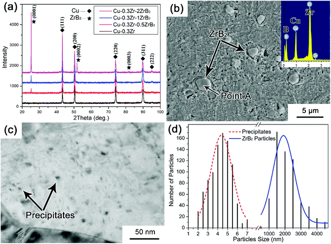
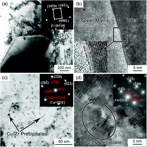
We prepared four Cu–Zr–(ZrB2) composites with nominal ZrB2 mass fractions of 0, 0.5, 1.0, and 2.0. The XRD patterns of the Cu–Zr–ZrB2 composites are shown in Fig. 1(a). Only two types of signals, which correspond to Cu and ZrB2 reflections, can be distinguished in the XRD spectra. The ZrB2 peaks become increasingly evident with increasing ZrB2 content, indicating that ZrB2 reinforcement can be quantitatively controlled by the in situ casting method. The SEM image in Fig. 1(b) shows that the ZrB2 particles are microsized and homogeneously distributed in the matrix. The EDS pattern provided in the inset of Fig. 1(b) also confirms the formation of ZrB2. Fig. 1(c) shows the TEM image of the Cu–0.3Zr–1ZrB2 composite, and many nanoparticles are detected throughout the matrix. Fig. 1(d) presents the size distribution of the ZrB2 particles and precipitates statistically measured from the SEM and TEM images. It can be seen that the particles (ZrB2 and precipitates) have a bimodal size distribution with a mean ZrB2 particle size of ∼2 μm and mean precipitate particle size of ∼5 nm.The TEM results of the Cu–Zr–ZrB2 composites are shown in Fig. 2. Fig. 2(a) shows the typical bright-field TEM images of the microparticle/Cu pairs in the composite. The selected area electron diffraction (SAED) patterns of the particle correspond to ZrB2. The ZrB2 particle is blocky and has straight boundaries with the copper matrix. Fig. 2(b) is a high-resolution TEM image showing the ZrB2–Cu interface, which is clean and reveals no undesirable reaction products. However, a transition layer with relatively high strain is noted at the interface, which is ascribed to the high lattice mismatch between ZrB2 and Cu. The disregistry between Cu and ZrB2 is calculated according to δ = 2(aZrB2 − aCu)/(aZrB2 + aCu) to be 13.16% based on their lattice parameters. The tight interfacial bonding is a prerequisite to attain superior mechanical properties that are conducive to improving the tribological performance of the composite.
The higher-magnified bright-field TEM image (Fig. 2(c)) shows the nanoparticles distributed inside the Cu grains. These particles, which were precipitated from the supersaturated Cu–Zr solid solution upon aging, are indexed as Cu5Zr by SAED analysis in the inset of Fig. 2(c). According to the SAED in Fig. 2(c), the zone axes of both Cu5Zr and the Cu matrix are [111], and the orientation relationship between the two is determined to be (20![[2 with combining macron]](https://www.rsc.org/images/entities/char_0032_0304.gif) )Cu5Zr//(20
)Cu5Zr//(20![[2 with combining macron]](https://www.rsc.org/images/entities/char_0032_0304.gif) )Cu and [111]Cu//[111]Cu5Zr. This is further evidenced by the high-resolution TEM analysis in Fig. 2(d). The corresponding SAED of [112] zone axis also confirm the Cu5Zr precipitate and the orientation relationship. These nanosized Cu5Zr precipitates are believed to be responsible for improving the tensile properties of the composites.
)Cu and [111]Cu//[111]Cu5Zr. This is further evidenced by the high-resolution TEM analysis in Fig. 2(d). The corresponding SAED of [112] zone axis also confirm the Cu5Zr precipitate and the orientation relationship. These nanosized Cu5Zr precipitates are believed to be responsible for improving the tensile properties of the composites.
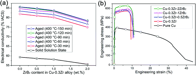
The variations of the electrical conductivity of the as-solution-annealed and as-aged Cu–Zr–(ZrB2) composites as a function of ZrB2 content are shown in Fig. 3(a). After aging, the electrical conductivity increases significantly, from about 55–60% International Annealed Copper Standard (IACS) to 78–86% IACS for the as-solution-annealed and as-aged samples, respectively, depending on the ZrB2 level. When the aging time increases from 30 min to 120 min at 400 °C, the electrical conductivity increases slightly and does not visibly improve when the aging time increases from 120 min to 150 min, which indicates that sufficient precipitation has occurred in the composites during a 120 min aging process. The electrical conductivity of Cu–Zr–ZrB2 slightly decreases from about 85% IACS to 78% IACS with an increase in ZrB2 content. Matthiessen's rule can be expressed as ρ = ρ(T) + ρi, where ρ is the total resistivity of the metals, ρ(T) is the resistivity of the metal, which varies with temperature, and ρi is the resistivity induced by chemical and physical defects including impurity atoms, interstitial defects, dislocations, and so on.28,29 The crystal lattice distortion caused by solid solution Zr atoms will scatter electrons intensively and significantly decrease the electrical conductivity. Therefore, separating Cu5Zr from the copper matrix could reduce the number of solid solution Zr atoms, leading to a considerable increase in the electrical conductivity.
 | ||
| Fig. 3 Electrical conductivity and tensile strength of Cu–Zr–(ZrB2) composites: (a) electrical conductivity and (b) stress–strain curves. | ||
The stress–strain curves of the Cu–0.3Zr–xZrB2 composites are compared with those of pure copper and of the Cu–0.3Zr alloy, as shown in Fig. 3(b). One can see that, compared with pure copper, the tensile tests only record marginal differences in the yield strength and ultimate tensile strength (UTS) between the samples with various ZrB2 contents, indicating that the large ZrB2 particles contribute little to the strength of the composite. This is probably because the strengthening of the Cu–0.3Zr–xZrB2 composites is dominated by the Orowan mechanism, as can be calculated by the following equation:30
ΔσOrowan = 0.13 Gb![[thin space (1/6-em)]](https://www.rsc.org/images/entities/char_2009.gif) ln(r/b)/λ, ln(r/b)/λ,
| (1) |
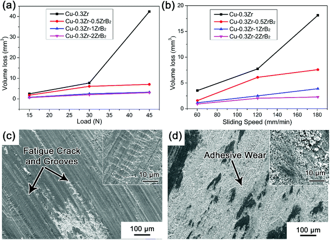
The effect of different loads and sliding speeds on the volume wear loss of the Cu–Zr–(ZrB2) pin samples are summarized in Fig. 4(a) and (b). Compared with Cu–Zr–ZrB2, a higher volume wear loss can be observed for the Cu–0.3Zr alloy without incorporation of ZrB2, especially at higher load (45 N) and sliding speed (150 rpm). This evidence confirms the effectiveness of the in situ formed ZrB2 particles in improving the wear resistance of copper alloys. The wear scar features of the Cu–0.3Zr alloy and Cu–0.3Zr–1ZrB2 composite are presented in Fig. 4(c) and (d), respectively. For the Cu–Zr alloy, fatigue cracks are found to be perpendicular to the scratch (high resolution at the right high corner). A mass of wear debris can be seen at the end of grooves, indicating that the debris plow grooves in the contact surfaces, where severe wear loss occurs. Unlike the Cu–Zr alloy, the sliding surface of Cu–0.3Zr–1ZrB2 features adhesive wear and fewer grooves, indicating that the ZrB2 particles resist the occurrence of fatigue crack. Therefore, the Cu–Zr–ZrB2 composites exhibit superior wear resistance.
 | ||
| Fig. 4 Volume wear loss of Cu–Zr–(ZrB2) composites: (a) different loads and (b) different sliding speeds. Wear scar of (c): Cu–0.3 wt% Zr and (d) Cu–0.3 wt% Zr–1 wt% ZrB2. | ||
Conclusions
In conclusion, we developed a dual-scale particulate-reinforced Cu–Zr–ZrB2 composite with ZrB2 microparticles and Cu5Zr precipitate nanoparticles fabricated by an ingot metallurgy route with a low cost. The ZrB2 microparticles contribute to the wear resistance, while the Cu5Zr precipitate nanoparticles enhance the strength by Orowan strengthening. In the laboratory, we obtained a combined UTS of 591 MPa, good wear resistance, and an acceptable electrical conductivity of 83.7% IACS for the Cu–0.3 wt% Zr–1 wt% ZrB2 composite.Conflicts of interest
There are no conflicts to declare.Acknowledgements
The authors gratefully acknowledge the support of the National Key Research and Development Program of China (No. 2017YFA0403804), the National Natural Science Foundation of China (No. 51525401, 51601028, 51774065, 51690163) and Dalian Support Plan for Innovation of High-level Talents (Top and Leading Talents, 2015R013).Notes and references
- X. Zhang, C. Shi, E. Liu, F. He, L. Ma, Q. Li, J. Li, W. Bacsa, N. Zhao and C. He, Nanoscale, 2017, 9, 11929–11938 RSC.
- A. Mortensen and J. Llorca, Annu. Rev. Mater. Res., 2010, 40, 243–270 CrossRef.
- I. Firkowska, A. Boden, B. Boerner and S. Reich, Nano Lett., 2015, 15, 4745–4751 CrossRef PubMed.
- C. N. He, N. Q. Zhao, C. S. Shi, E. Z. Liu and J. J. Li, Adv. Mater., 2015, 27, 5422–5431 CrossRef PubMed.
- K. Bi, Q. Xiang, Y. Chen, H. Shi, Z. Li, J. Lin, Y. Zhang, Q. Wan, G. Zhang, S. Qin, X. Zhang and H. Duan, Nanoscale, 2017, 9, 16755–16763 RSC.
- S. C. Tjong and Z. Y. Ma, Mater. Sci. Eng., R, 2000, 29, 49–113 CrossRef.
- L. Lu, Y. Shen, X. Chen, L. Qian and K. Lu, Science, 2004, 304, 422 CrossRef PubMed.
- R. Li, H. Kang, Z. Chen, G. Fan, C. Zou, W. Wang, S. Zhang, Y. Lu, J. Jie, Z. Cao, T. Li and T. Wang, Sci. Rep., 2016, 6, 20799 CrossRef PubMed.
- W. Wang, H. Kang, Z. Chen, Z. Chen, C. Zou, R. Li, G. Yin and T. Wang, Mater. Sci. Eng., A, 2016, 673, 378–390 CrossRef.
- J. Zhang, L. He and Y. Zhou, Scr. Mater., 2009, 60, 976–979 CrossRef.
- Y. Zhan and G. Zhang, Mater. Lett., 2003, 57, 4583–4591 CrossRef.
- J. P. Tu, N. Y. Wang, Y. Z. Yang, W. X. Qi, F. Liu, X. B. Zhang, H. M. Lu and M. S. Liu, Mater. Lett., 2002, 52, 448–452 CrossRef.
- J. W. Kaczmar, K. Pietrzak and W. Wlosinski, J. Mater. Process. Technol., 2000, 106, 58–67 CrossRef.
- X. Wang, H. Ding, F. Qi, Q. Liu, X. Fan and Y. Shi, J. Alloys Compd., 2017, 695, 3410–3418 CrossRef.
- R. Aparicio-Fernández, H. Springer, A. Szczepaniak, H. Zhang and D. Raabe, Acta Mater., 2016, 107, 38–48 CrossRef.
- C. Zou, H. Kang, W. Wang, Z. Chen, R. Li, X. Gao, T. Li and T. Wang, J. Alloys Compd., 2016, 687, 312–319 CrossRef.
- D. Deschuyteneer, F. Petit, M. Gonon and F. Cambier, Surf. Coat. Technol., 2017, 311, 365–373 CrossRef.
- C. Zou, Z. Chen, H. Kang, W. Wang, R. Li, T. Li and T. Wang, Wear, 2017, 392–393, 118–125 CrossRef.
- W. S. Miller and F. J. Humphreys, Scr. Metall. Mater., 1991, 25, 33–38 CrossRef.
- J. B. Correia, H. A. Davies and C. M. Sellars, Acta Mater., 1997, 45, 177–190 CrossRef.
- F. X. Huang, J. S. Ma, H. L. Ning, Z. T. Geng, C. Lu, S. M. Guo, X. T. Yu, T. Wang, H. Li and H. F. Lou, Scr. Mater., 2003, 48, 97–102 CrossRef.
- L. Peng, H. Xie, G. Huang, Y. Li, X. Yin, X. Feng, X. Mi and Z. Yang, Mater. Sci. Eng., A, 2015, 633, 28–34 CrossRef.
- T. M. Wang, M. Y. Li, H. J. Kang, W. Wang, C. L. Zou and Z. N. Chen, J. Mater. Res., 2015, 30, 248–256 CrossRef.
- J. Ruzic, J. Stasic, V. Rajkovic and D. Bozic, Mater. Des., 2014, 62, 409–415 CrossRef.
- Z. Y. Yan, Z. Ma, L. Liu, S. Z. Zhu and L. H. Gao, J. Eur. Ceram. Soc., 2014, 34, 2203–2209 CrossRef.
- O. Yilmaz and S. Buytoz, Compos. Sci. Technol., 2001, 61, 2381–2392 CrossRef.
- F. Rana and D. M. Stefanescu, Metall. Trans. A, 1989, 20, 1564–1566 CrossRef.
- B. Lengeler, W. Schilling and H. Wenzl, J. Low Temp. Phys., 1970, 2, 59–86 CrossRef.
- W. E. Lawrence and J. W. Wilkins, Phys. Rev. B: Condens. Matter Mater. Phys., 1973, 7, 2317–2332 CrossRef.
- G. E. Dieter, Mechanical metallurgy SI Metric Edition, McGraw-Hill Book Company (UK) Limited, UK, 1988 Search PubMed.
- Q. Zhang and D. L. Chen, Scr. Mater., 2004, 51, 863–867 CrossRef.
Footnote |
| † These authors contributed equally to this work. |
| This journal is © The Royal Society of Chemistry 2018 |


