 Open Access Article
Hierarchical Co3O4@Co9S8 nanowall structures assembled by many nanosheets for high performance asymmetric supercapacitors
Lei Xing,
Yidi Dong and
Xiang Wu *
*
School of Materials Science and Engineering, Shenyang University of Technology, Shenyang 110870, China. E-mail: wuxiang05@163.com
First published on 6th August 2018
Abstract
Herein, we report hierarchical Co3O4@Co9S8 nanowalls assembled by many nanosheets. The as-synthesized products are characterized in detail using various characterization methods. They can be directly used as supercapacitor electrodes with excellent electrochemical performance due to the synergy effect between Co3O4 and Co9S8. Furthermore, a flexible asymmetric supercapacitor is fabricated by using the as-synthesized Co3O4@Co9S8 structures as the cathode and the active carbon as the anode, which reveals a specific capacitance of 266.6 mF cm−2 at a current density of 4 mA cm−2. In addition, the supercapacitor shows an excellent capacity retention rate of 86.5% after 10![[thin space (1/6-em)]](https://www.rsc.org/images/entities/char_2009.gif) 000 cycles at a current density of 10 mA cm−2. Finally, three supercapacitor devices connected in series can light a blue LED lamp for 5 min.
000 cycles at a current density of 10 mA cm−2. Finally, three supercapacitor devices connected in series can light a blue LED lamp for 5 min.
1. Introduction
In recent years, supercapacitors have been a research focus in the energy storage field. It is used widely in portable electronic devices, urban rail transit and uninterruptible power supplies.1–6 Supercapacitors are also called electrochemical capacitors, which can be divided in two categories, i.e., electric double layer capacitors that store energy by adsorption of pure electrostatic charge on the surface of the electrode, and pseudocapacitors where reversible redox reactions occur at the surface and near the surface of the electrode material. They inherit the advantages of traditional capacitors with high power density and overcome the disadvantages of low capacitance and complex circuit structure.7,8 Compared with traditional batteries, supercapacitors possess characteristics of high charging–discharging speed and long cycle life.9–11In general, pseudocapacitor electrode materials such as metal oxides and conductive polymers present higher specific capacitance than double electric layer capacitors.12,13 Recently, various pseudocapacitor electrode materials such as transition metal oxides and sulphides,14–18 conductive polymers,19 hydroxides20,21 have been reported. Among them, transition metal oxides have relatively high specific surface areas, short electron and ion transmission channels.22 Especially, Co3O4 nanomaterials have received extensive attention due to their excellent electrochemical performance with high theoretical specific capacitance (3560 F g−1). However, in practice application, single Co3O4 materials possess poor electrode stability and low cyclic stability.23,24 Therefore, one has designed various hybrid structures to use their synergetic effect to improve the electrochemical properties of Co3O4 nanomaterials. Du et al. successfully synthesized porous Co3O4 nanosheets@RGo nanocomposite using a simple hydrothermal process. The electrode material exhibits excellent specific capacitance of 894 F g−1 at a current density of 1 A g−1.25 Zhang et al. adjusted surface composition and defects of Co3O4 electrode material by controlling the calcination temperature to improve the electrochemical performance. The electrode material shows a high specific capacitance (739 F g−1 at 5 mV s−1) and has excellent cycle stability.26
Herein, we successfully fabricated hierarchical Co3O4@Co9S8 nanowalls on the nickel foam by a continuous hydrothermal method and used them as the cathodes for a flexible and quasi-solid supercapacitor. In this heterostructure, the original Co3O4 nanosheets will serve as the support skeletons for Co9S8 growth. The Co9S8 layers are not only can enhance the capacitance but also acts as a conductive layer to shorten the ion diffusion distance. The detailed electrochemical tests show that the specific capacitances can reach 4523.6 mF cm−2 and 1512.7 F g−1 at current density of 4 mA cm−2 and 4 A g−1. An asymmetric supercapacitor is assembled using Co3O4@Co9S8 nanowalls electrode as the cathode and activated carbon (AC) as the anode material, respectively. The fabricated supercapacitor shows good electrochemical performance with the energy density of 0.416 mW h cm−3 when power density reach 14.994 W cm−3.
2. Experimental details
2.1 Material preparation
For the synthesis, all the chemicals were analytical grade and used as received without further purification. Co3O4 nanowalls were grown on nickel foam by a simple hydrothermal method. In order to remove the oxide layer from nickel foam, it was treated with 2 M hydrochloric acid followed by ultrasonic cleaning using distilled water and alcohol, sequentially. In a typical synthesis process, 0.582 g of Co(NO3)2, 0.185 g of NH4F and 0.6 g of urea are dissolved in 60 ml of distilled water and stirred for 30 min to form a stable suspension. The solution was then transferred to a Teflon-lined stainless steel autoclave and the pre-treated nickel foam was immersed in the aqueous solution. The autoclave was then sealed and heated to 120 °C for 6 h. After completing the reaction at desired time, the autoclave was cooled to room temperature and the as-obtained product was washed several times to remove un-reacted reactants. The product was finally dried at 60 °C for 6 h and calcined at 350 °C for 2 h in a muffle furnace. Hierarchical Co3O4@Co9S8 nanowalls were synthesized via a same hydrothermal process. In detail, 0.35 g Na2S·2H2O, 50 ml DI water and the as-prepared Co3O4 nanosheet on Ni foam were placed into a 100 ml Teflon-lined autoclave. The temperature was maintained at 120 °C for 6 h and then cooled down to room temperature naturally.2.2 Material characterizations
The phase and crystallinity of the as-prepared products were characterized by X-ray powder diffraction (XRD, Rigaku Dmax-rB, Cu-Kα radiation, λ = 0.1542 nm, 40 kV, 100 mA). The morphology and microstructure of the as-synthesized samples were studied by scanning electron microscopy (Gemini SEM 300) and the chemical bonding states of the samples were examined using XPS measurements. The electrochemical workstation (CHI660E) was used to test the electrochemical properties.2.3 Electrochemical measurements
Electrochemical tests of Co3O4 and Co3O4@Co9S8 product as the working electrode were performed in 2 M KOH aqueous solution using a three-electrode system. The counter and reference electrodes were Pt electrode and Hg/HgO electrode, respectively. The working electrode area was 0.785 cm2, and the average load capacity of Co3O4@Co9S8 nanowalls in nickel foam was 2.70 mg cm−2. The work voltage was applied in the range of 0 to 0.55 V, and the curve was scanned at 5, 10, 20, 50, 100 mV s−1, respectively. GCD curves were measured at current densities of 4, 8, 10, 12 and 20 mF cm−2. The electrochemical impedance spectra (EIS) studies were performed in the frequency range from 0.01 kHz to 100 MHz with an amplitude of 10 mV. Area capacitance, energy density and power density of electrode materials were calculated according to the eqn (1)–(4), respectively as below:
 | (1) |
 | (2) |
 | (3) |
 | (4) |
2.4 Flexible asymmetric supercapacitor
To prepare the solid-state ASC devices, solid-state Co3O4@Co9S8 nanowalls//AC devices with Co3O4@Co9S8 nanosheet arrays as the cathode and AC as the anode. The separator (NKK separator, Nippon Kodoshi Corporation) and polymer electrolyte using PVA/KOH gel were used. To optimize the charges between the two electrodes, the area ratio of Co3O4@Co9S8 nanowalls electrode to AC electrode was 1![[thin space (1/6-em)]](https://www.rsc.org/images/entities/char_2009.gif) :
:![[thin space (1/6-em)]](https://www.rsc.org/images/entities/char_2009.gif) 1. PVA/KOH gel were prepared by dissolving 5 g of PVA and 3 g of KOH in 50 ml of distilled water and heated to 80 °C for 1 h under continuous stirring. The electrode and the separator were immersed in PVA/KOH electrolyte.
1. PVA/KOH gel were prepared by dissolving 5 g of PVA and 3 g of KOH in 50 ml of distilled water and heated to 80 °C for 1 h under continuous stirring. The electrode and the separator were immersed in PVA/KOH electrolyte.
3. Results and discussion
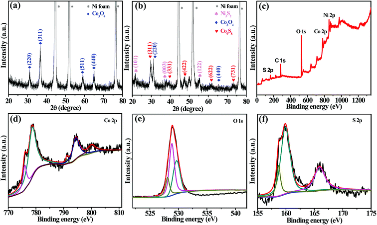
The crystallinity and crystal phases of the as-prepared products are first examined by X-ray diffraction. Fig. 1a demonstrates typical XRD pattern of Co3O4 nanowalls grown on Ni foam. The diffraction peaks located at 44.6°, 52.0° and 76.6° correspond to nickel peaks (JCPDS card no. 42-0712) from Ni foam. Several other diffraction peaks at 31.3°, 36.9°, 55.7°, 59.4° and 65.2° correspond to (220), (311), (422), (511) and (440) Co3O4 crystal planes (JCPDS card no. 42-1467), respectively. Fig. 1b shows XRD pattern of hybrid products. It exhibits several well defined diffraction peaks. Diffraction peaks at 21.7°, 37.7°, 55.1° are found to be Ni3S2 (JCPDS card no. 44-1418) due to the reaction of nickel foam with Na2S·2H2O. Other five diffraction peaks located at 29.7°, 39.4°, 44.8°, 61.7° and 73.3° are seen, which correspond to Co9S8 crystal planes of (311), (331), (422), (622) and (731), respectively. No characteristic peaks of other impurities are detected, indicating that the as-synthesized Co3O4@Co9S8 products have high purity. The well-defined and strong diffraction peaks clearly confirm well crystallinity of the synthesized samples.Fig. 1c shows XPS full spectrum of Co3O4@Co9S8 product. The main five characteristic peaks of Co, O, S, Ni and C are detected in XPS spectrum. Fig. 1d presents the Co 2p XPS fitting spectrum. The Co 2p spectrum exhibits two spin–orbit doublets characteristic of Co2+ and Co3+ and two shake-up satellites. The two major peaks with a high energy band at 778.7 eV for Co 2p 3/2 and a low energy band at 794.5 eV for Co 2p 1/2 are in accordance with the presence of Co3O4@Co9S8. The O 1s spectrum (Fig. 1e) also can be divided into three peaks centered at 528.0, 528.8 and 529.6 eV, which correspond to oxygen in the Co3O4, oxygen atoms in hydroxyl group as well as the absorbed water, respectively. Fig. 1f clearly demonstrates the XPS spectrum of the S 2p. S can be further identified by the two distinct 2p peaks at 159.9 eV and 165.9 eV. The XPS results further confirm the presence of Co3O4 and Co9S8 phases in the prepared Co3O4@Co9S8 product.27
The morphology of Co3O4 nanowalls and Co3O4@Co9S8 nanowalls are observed using SEM. Fig. 2a and b show the general morphology of Co3O4 nanosheets on nickel foam. It can be clearly seen that Co3O4 nanosheets are woven by many nanowires. The surface texture of the nanosheets is not uniform and clearly showing porous characteristic. Co3O4 nanosheet thickness is about 20 nm. Fig. 2c and d show SEM images of Co3O4@Co9S8 nanowalls. Many Co3O4@Co9S8 nanosheets are well aligned on Ni foam. The typical thickness of Co3O4@Co9O8 nanosheets is in the range of 30 ± 5 nm.
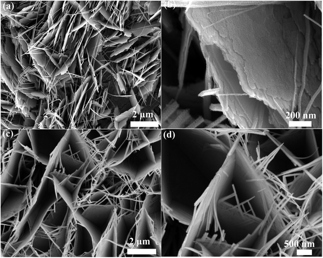 | ||
| Fig. 2 (a and b) SEM images of Co3O4 nanowalls grown on Ni foam (c and d) SEM images of Co3O4@Co9S8 nanowalls. | ||
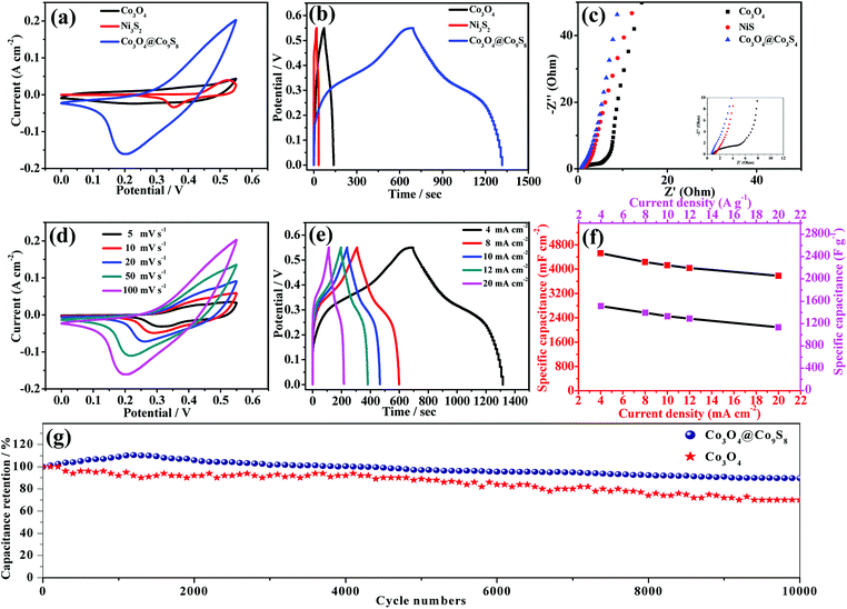
Electrochemical properties of Co3O4 and Co3O4@Co9S8 nanowalls in 2 M KOH aqueous solution are studied. Fig. 3a shows the cyclic voltammetry of Co3O4, Ni3S2 and Co3O4@Co9S8 product at sweep rate of 100 mV s−1. It can be seen that all samples present pseudocapacitive CV curves. Remarkably, the contribution from Ni3S2 can be negligible due to the small integrated area. At the same time, the closed area of CV curve of Co3O4@Co9S8 electrode is much larger than that of the original Co3O4. The improved capacitance results from the increased reactive sites due to a plenty of Co9S8 nanocrystals wrapped over the Co3O4 nanosheet effectively. As shown in Fig. 3b, the galvanostatic charging/discharging measurements of Co3O4, Ni3S2 and Co3O4@Co9S8 product are further conducted at current density of 4 mA cm−2. As expected, the Co3O4@Co9S8 electrode exhibits much longer discharging time than Co3O4 electrode. According to the formula (1), area capacitance Co3O4@Co9S8 product can reach 4523.6 mF cm−2. The capacity of Co3O4 and Ni3S2 reach only 464.2 mF cm−2 and 111.2 mF cm−2. The main reason for the increase in capacity may be the synergy effect between the Co3O4 and Co9S8.28 Fig. 3c shows the electrochemical impedance spectroscopy (EIS) of the original Co3O4, Ni3S2 and Co3O4@Co9S8 product. It can be observed that the Nyquist plots consist of a linear part in low frequency region and a semicircle part in high frequency region. The slope of the straight line in the low-frequency region is associated with the diffusive resistance. Their nearly vertical slope demonstrates the fast ion diffusion and the ideal capacitive behavior of these electrodes. Besides, the intercept of the plots at the X axis in high-frequency range represents the equivalent series resistance (ESR) of the electrodes. The intercept of the Nyquist curve on the real axis is about 0.76 Ω, indicating that Co3O4@Co9S8 electrode has good conductivity and low internal resistance. Similarly, the Co3O4@Co9S8 nanosheet arrays electrode shows much smaller semicircle diameter in high-frequency range than that of Co3O4 electrode. The low Rct is beneficial to fast charge transfer, which is derived from excellent infiltration of electrolyte and the shortened diffusion path of ions.29
In order to study the influence of the scan rates on the electrochemical performance of Co3O4@Co9S8 electrode, CV curves of the samples are performed at various scan rates ranging from 5 to 100 mV s−1, as shown in Fig. 3d. It can be seen that the redox peaks of Co3O4@Co9S8 electrode move to both sides as the scan rate increases due to the polarization effect of the electrodes. In order to get more information about the performance of Co3O4@Co9S8 electrodes, a series of charge–discharge test are carried out at a voltage range of 0–0.55 V with current densities of 4, 8, 10, 12 and 20 mA cm−2. As shown in Fig. 3e, all the galvanostatic charging/discharging plots show a typical nonlinear behavior at different current densities ranging from 4 to 20 mA cm−2, revealing pseudocapacitive nature of the samples. Fig. 3f shows the area specific capacitance of Co3O4@Co9S8 electrodes at different current densities. The area capacitances of Co3O4@Co9S8 electrodes are 4523.6, 4232.7, 4127.2, 4036.3 and 3781.8 mF cm−2 at current densities of 4, 8, 10,12 and 20 mA cm−2, respectively. Similarly, according to formula (2), the mass specific capacitance of Co3O4@Co9S8 electrodes are 1512.7, 1396.3, 1330.9, 1289.4 and 1134.5 F g−1 at current densities of 4, 8, 10,12 and 20 A g−1 respectively. To test the cycle stability of the as-prepared samples, the repeated charge and discharge cycled are performed at a current density of 20 mA cm−2, as shown in Fig. 3g. Their specific capacitance gradually increases in the initial phase, which might be attributed to gradual activation of the active materials. After 10![[thin space (1/6-em)]](https://www.rsc.org/images/entities/char_2009.gif) 000 charge and discharge cycles the specific capacitance reduce to 4057.6 mF cm−2, which is equivalent the retention rate of 89.7%. The excellent cycling stability is mainly attributed to many vacancies, from rough surface effect, which can not only lead to more contact area with the electrolyte, but also accommodate possible volume change during cycling process.30,31
000 charge and discharge cycles the specific capacitance reduce to 4057.6 mF cm−2, which is equivalent the retention rate of 89.7%. The excellent cycling stability is mainly attributed to many vacancies, from rough surface effect, which can not only lead to more contact area with the electrolyte, but also accommodate possible volume change during cycling process.30,31
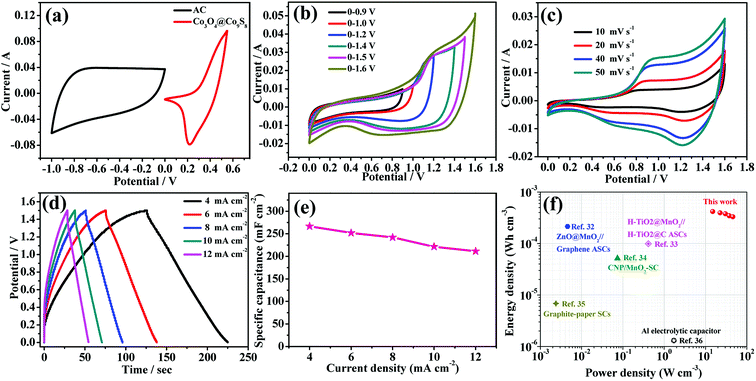
To further investigate the practical application of the as-synthesized electrode materials, a asymmetric supercapacitor is assembled using AC as anode, Co3O4@Co9S8 nanowalls as cathode and the typical PVA/KOH as gel-like electrolyte (denoted as Co3O4@Co9S8//AC ASC). According to the charge balance (q+ = q−), the mass balance between the positive and negative electrode can be obtained via m−/m+ = (C+ × ΔV+)/(C− × ΔV−), where C+ and C− is the capacitance of the electrodes, ΔV+ and ΔV− is the corresponding voltage range for charging–discharging process, hence the loading mass of AC electrode is ∼14.4 mg cm −2 after balance. Before assembling, CV curves of both AC electrode and Co3O4@Co9S8 electrode are tested at the scan rate of 100 mV s −1 in a three-electrode system, as shown in Fig. 4a. Based on the single-electrode CV curve, AC and Co3O4@Co9S8 product provide a stable voltage window between −1 to 0 V and 0–0.55 V, respectively. Therefore, when assembled into a flexible asymmetric supercapacitor, the operating voltage could be extended to approximately 1.6 V. Fig. 4b shows the CV curve of Co3O4@Co9S8 nanowalls//AC ASC at a swept rate of 100 mV s−1 and a voltage window of 0.9–1.6 V. All the curves show that Co3O4@Co9S8 nanowalls//AC ASC operates at a 1.6 V operating voltage. From Fig. 4c, the as-prepared asymmetric supercapacitor is tested at various scan rates ranging from 10 to 50 mV s−1 in the potential window of 0 to 1.5 V. As the scan rate increased, closed areas are augmentative while the shapes remain quasi-rectangular. The quasi-rectangular CV geometry indicates the obvious redox characteristics. Galvanostatic charging/discharging testing of Co3O4@Co9S8//AC ASC under various current densities are shown in Fig. 4d. The charge–discharge curves are almost symmetrical, revealing the perfect electrochemical behavior of the as-prepared asymmetric supercapacitor. Fig. 4e shows area specific capacitance of 266.6, 252.0, 242.0, 221.3, 211.2 mF cm−2 at the current density of 4, 6, 8, 10, 12 mA cm−2, respectively. Fig. 4f is a Ragone plot based on energy density and power density of a asymmetric supercapacitor. At a current density of 4 mA cm−2, its power density is 14.99 W cm−3, and its maximum energy density is 0.416 mW h cm−3, which is superior to the previously reported.32–36
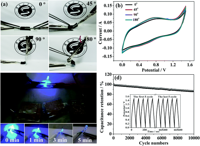
Excellent mechanical performance of supercapacitor device is particularly important in portably flexible electronic products. Therefore, to further study the mechanical flexibility of the as-fabricated Co3O4@Co9S8 nanowalls//AC ASCs device under real conditions, a device bended experiments at various angles and its CV measurements are carried out. Fig. 5a shows the pictures of the ASC device with a bending angle of 0°, 45°, 90°, and 180°, the corresponding CV curves at a scan rate of 100 mV s−1 is showed in Fig. 5b. The shape and the area of CV curves remain almost the same, revealing that the hybrid electrode has excellent mechanical properties. To further test the feasibility of practical application of Co3O4@Co9S8//AC ASC, the devices are used to drive a 5 mm diameter LEDs, as shown in Fig. 5c. The ASC can successfully power one LEDs (3.2 V) for 5 min after full charging. Furthermore, the cycling performance of Co3O4@Co9S8//AC ASCs is also a key factor to evaluate the supercapacitor performance, and thus the ASC device is cycled for 10![[thin space (1/6-em)]](https://www.rsc.org/images/entities/char_2009.gif) 000 cycles between 0–1.5 V at a current density of 20 mA cm−2, as seen in Fig. 5d. This asymmetric supercapacitor device shows excellent long-term cycle stability with the retention rate of 86.5% after 10
000 cycles between 0–1.5 V at a current density of 20 mA cm−2, as seen in Fig. 5d. This asymmetric supercapacitor device shows excellent long-term cycle stability with the retention rate of 86.5% after 10![[thin space (1/6-em)]](https://www.rsc.org/images/entities/char_2009.gif) 000 cycles.
000 cycles.
4. Conclusions
In summary, Co3O4@Co9S8 nanowalls as supercapacitor electrode materials are successfully synthesized on Ni foam by a hydrothermal method. Co3O4 nanosheets as the base substrate for Co9S8 deposition can improve the cyclic stability of the electrode and the synergistic effect of these electrodes leads to an excellent electrochemical performance for the as-prepared Co3O4@Co9S8 nanowalls. Assembled asymmetrical supercapacitors exhibit high energy density and power density, which can to drive a blue LED lamp for 5 min. In addition, the asymmetric supercapacitor has excellent mechanical properties and long cycle stability.Conflicts of interest
There are no conflicts to declare.Acknowledgements
This work was supported by Nature Science Fund of Liaoning Province (No. 20170540671).References
- D. V. Pham, R. A. Patil, C. C. Yang, W. C. Yeh, Y. Liou and Y. R. Ma, Nano Energy, 2018, 47, 105–114 CrossRef.
- W. Jiang, F. Hu, Q. Y. Yan and X. Wu, Inorg. Chem. Front., 2017, 4, 1642–1648 RSC.
- N. P. Sari, D. Dutta, A. Jamaluddin, J. K. Chang and C. Y. Su, Phys. Chem. Chem. Phys., 2017, 19, 30381–30392 RSC.
- D. P. Zhao, F. Hu, A. Umar and X. Wu, New J. Chem., 2018, 42, 7399–7406 RSC.
- X. Hu, W. Zhang, X. Liu, Y. Mei, Y. Mei and Y. Huang, Chem. Soc. Rev., 2015, 44, 2376–2404 RSC.
- C. Liu, W. Jiang, F. Hu, X. Wu and D. F. Xue, Inorg. Chem. Front., 2018, 5, 835–843 RSC.
- L. L. Xing, K. J. Huang and L. X. Fang, Dalton Trans., 2016, 45, 17439–17446 RSC.
- G. P. Xiong, P. G. He, D. N. Wang, Q. Q. Zhang, T. F. Chen and T. S. Fisher, Adv. Funct. Mater., 2016, 26, 5460–5470 CrossRef.
- X. Wu and S. Y. Yao, Nano Energy, 2017, 42, 143–150 CrossRef.
- T. Zhai, L. M. Wan, S. Sun, Q. Chen, J. Sun, Q. Y. Xia and H. Xia, Adv. Mater., 2017, 29, 1604167 CrossRef PubMed.
- L. Xing, Y. D. Dong, F. Hu, X. Wu and A. Umar, Dalton Trans., 2018, 47, 5687–5694 RSC.
- X. Wu, Z. C. Han, X. Zheng, S. Y. Yao, X. Yang and T. Y. Zhai, Nano Energy, 2016, 31, 410–417 CrossRef.
- N. Jabeen, A. Hussain, Q. Y. Xia, S. Sun, J. W. Zhu and H. Xia, Adv. Mater., 2017, 29, 1700804 CrossRef PubMed.
- Y. Liu, Y. Jiao, Z. L. Zhang, F. Y. Qu, A. Umar and X. Wu, ACS Appl. Mater. Interfaces, 2014, 6, 2174–2184 CrossRef PubMed.
- H. Xia, C. Y. Hong, X. Q. Shi, B. Li, G. L. Yuan, Q. F. Yao and J. P. Xie, J. Mater. Chem. A, 2015, 3, 1216–1221 RSC.
- Y. Jiao, Y. Liu, B. S. Yin, S. W. Zhang, F. Y. Qu and X. Wu, Nano Energy, 2014, 10, 90–98 CrossRef.
- C. Liu and X. Wu, Mater. Res. Bull., 2018, 103, 55–62 CrossRef.
- S. W. Zhang, B. S. Yin, H. Jiang, F. Y. Qu, A. Umar and X. Wu, Dalton Trans., 2015, 44, 2409–2415 RSC.
- M. Zhu, Y. Huang, Y. Huang, H. Li, Z. Wang, Z. Pei, Q. Xue, H. Geng and C. Zhi, Adv. Mater., 2017, 29, 1605137 CrossRef PubMed.
- F. Y. Liu, X. Chu, H. T. Zhang, B. B. Zhang, H. Su, L. Jin, Z. X. Wang, H. C. Huang and W. Q. Yang, Electrochim. Acta, 2018, 269, 102–110 CrossRef.
- H. Y. Liang, J. H. Lin, H. N. Jia, S. L. Chen, J. L. Qi, J. Cao, T. S. Lin, W. D. Fei and J. C. Feng, J. Power Sources, 2018, 378, 248–254 CrossRef.
- S. Kumar, G. Saeed, N. H. Kim and J. H. Lee, J. Mater. Chem. A, 2018, 6, 7182–7193 RSC.
- Z. C. Han, X. Zheng, S. Y. Yao, H. H. Xiao, F. Y. Qu and X. Wu, Appl. Surf. Sci., 2016, 365, 240–244 CrossRef.
- M. Kim, J. Choi, I. Oh and J. Kim, Phys. Chem. Chem. Phys., 2016, 18, 19696–19704 RSC.
- F. Du, X. Q. Zuo, Q. Yang, G. Li, Z. L. Ding, M. Z. Wu, Y. Q. Ma, S. W. Jin and K. R. Zhu, Electrochim. Acta, 2016, 222, 976–982 CrossRef.
- G. H. Cheng, T. Y. Kou, J. Zhang, C. H. Si, H. Gao and Z. H. Zhang, Nano Energy, 2017, 38, 155–166 CrossRef.
- Q. Wang, L. Jiao, H. Du, Y. Si, Y. Wang and H. Yuan, J. Mater. Chem. A, 2012, 22, 21387–21391 RSC.
- P. Sennu, V. Aravindan and Y. S. Lee, J. Power Sources, 2016, 306, 248–257 CrossRef.
- Y. Zhao, L. F. Hu, S. Y. Zhao and L. M. Wu, Adv. Funct. Mater., 2016, 26, 4085–4093 CrossRef.
- A. L. Dang, T. H. Li, C. Y. Xiong, T. K. Zhao, Y. D. Shang, H. G. Liu, X. D. Chen, H. Li, Q. Zhuang and S. Z. Zhang, Composites, Part B, 2018, 141, 250–257 CrossRef.
- M. Suominen, P. Damlin, S. Granroth and C. Kvarnstrom, Carbon, 2018, 128, 205–214 CrossRef.
- M. F. El-Kady, V. Strong, S. Dubin and R. B. Kaner, Science, 2012, 335, 1326–1330 CrossRef PubMed.
- L. Yuan, B. Yao, B. Hu, K. Huo, W. Chen and J. Zhou, Energy Environ. Sci., 2013, 6, 470–476 RSC.
- L. Yuan, X. H. Lu, X. Xiao, T. Zhai, J. Dai, F. Zhang, B. Hu, X. Wang, L. Gong, J. Chen, C. Hu, Y. Tong, J. Zhou and Z. L. Wang, ACS Nano, 2012, 6, 656–661 CrossRef PubMed.
- Z. J. Fan, J. Yan, T. Wei, L. J. Zhi, G. Q. Ning, T. Y. Li and F. Wei, Adv. Funct. Mater., 2011, 21, 2366–2375 CrossRef.
- D. Kong, C. Cheng, Y. Wang, J. I. Wong and Y. Yang, J. Mater. Chem. A, 2015, 3, 16150–16161 RSC.
| This journal is © The Royal Society of Chemistry 2018 |

