
 Open Access Article
 This Open Access Article is licensed under a
 Creative Commons Attribution 3.0 Unported Licence
New insights into the surface plasmon resonance (SPR) driven photocatalytic H2 production of Au–TiO2†
Jinlin Nieab,
Jenny Schneiderb,
Fabian Sieland b,
Long Zhoua,
Shuwei Xia*a and
Detlef W. Bahnemann*bc
b,
Long Zhoua,
Shuwei Xia*a and
Detlef W. Bahnemann*bc
aKey Laboratory of Marine Chemistry Theory and Technology, Ministry of Education, College of Chemistry and Chemical Engineering, Ocean University of China, Songling Road 238, 266100 Qingdao, China. E-mail: shuweixia@ouc.edu.cn
bInstitut für Technische Chemie, Leibniz Universität Hannover, Callinstr. 3, D-30167 Hannover, Germany. E-mail: bahnemann@iftc.uni-hannover.de
cLaboratory “Photoactive Nanocomposite Materials”, Saint-Petersburg State University, Ulyanovskaya Str. 1, Peterhof, 198504 Saint-Petersburg, Russia
First published on 19th July 2018
Abstract
The Surface Plasmon Resonance (SPR) driven photocatalytic H2 production upon visible light illumination (≥500 nm) was investigated on gold-loaded TiO2 (Au–TiO2). It has been clearly shown that the Au-SPR can directly lead to photocatalytic H2 evolution under illumination (≥500 nm). However, there are still some open issues about the underlying mechanism for the SPR-driven photocatalytic H2 production, especially the explanation of the resonance energy transfer (RET) theory and the direct electron transfer (DET) theory. In this contribution, by means of the EPR and laser flash photolysis spectroscopy, we clearly showed the signals for different species formed by trapped electrons and holes in TiO2 upon visible light illumination (≥500 nm). However, the energy of the Au-SPR is insufficient to overcome the bandgap of TiO2. The signals of the trapped electrons and holes originate from two distinct processes, rather than the simple electron–hole pair excitation. Results obtained by Laser Flash Photolysis spectroscopy evidenced that, due to the Au-SPR effect, Au NPs can inject electrons to the conduction band of TiO2 and the Au-SPR can also initiate e−/h+ pair generation (interfacial charge transfer process) upon visible light illumination (≥500 nm). Moreover, the Density Functional Theory (DFT) calculation provided direct evidence that, due to the Au-SPR, new impurity energy levels occurred, thus further theoretically elaborating the proposed mechanisms.
1. Introduction
Photocatalytic H2 evolution from water utilizing sun light is gaining importance for providing clean and sustainable energy.1–3 However, for practical applications, photocatalysts are desired to work efficiently under visible light which accounts for nearly half of the solar light.4 Recently, the rapid advances in plasmonic photocatalysis have accelerated the progress in the visible-light harvesting ability of TiO2-based photocatalysts. For instance, it has been reported that the surface-loading of Au nanoparticles can greatly increase the photocatalytic H2 production ability of Au–TiO2 upon visible light illumination.4–9However, the underlying mechanism remains unclear in the respective literatures.4a,10–14 Generally, two main mechanisms have been proposed to explain the visible light activity of Au–TiO2 photocatalysts (summarized in Fig. 1). The first mechanism known as resonance energy transfer (RET) is based on the idea that the SPR enhances the local electromagnetic field which in turn facilitates the generation of e−/h+ pairs near the semiconductor surface;3,11,12 D. B. Ingram11 and Z. W. Seh12 proposed this mechanism according to their results based on finite-difference time-domain (FDTD) simulations and discrete-dipole approximation (DDA) simulations, respectively, yet without exhibiting any experimental evidence. In addition, K. Awazu15 also obtained results supporting this mechanism when adding an insulating layer between the noble metal nanoparticles and the semiconductor. In this study, the plasmonic metal nanoparticles were homogeneously covered with a SiO2 shell thus preventing the direct electron transfer process. However, due to the energy transfer the enhanced photocatalytic activity was still achieved. The second mechanism explains the visible activity of Au–TiO2 by the SPR-excited electron transfer from the Au nanoparticles to the conduction band of TiO2, known as direct electron transfer (DET).4a,10,13,16 C. Gomes Silva10 and coworkers proposed this mechanism based on the observation that Au–TiO2 photocatalysts exhibit photocatalytic activity for H2 evolution upon 532 nm laser illumination. Recently, J. B. Priebe et al.4a provided experimental evidence for the DET mechanism based on results obtained employing electron paramagnetic resonance (EPR) spectroscopy. In the EPR measurements, the authors detected the signals for electrons trapped at oxygen vacancies and for Ti3+ ions, which was considered as evidence for the electron transfer process from Au to TiO2. Herein, it was emphasized that the absorption of TiO2 is situated absolutely below 420 nm, therefore, the signals occurred due to the action of the Au nanoparticles rather than of TiO2. Moreover, it was excluded that the signals originated from electrons located in the Au nanoparticles themselves, as much higher g values and line widths are the requisites for these electrons to yield such signals.4 In conclusion, J. B. Priebe and co-worker argued that the obtained EPR-signals provide evidence for trapped electrons in TiO2 thus indicating a hot electron injection from the Au nanoparticles to TiO2. However, it should be mentioned here that the results obtained by these EPR measurements can also be explained by means of the RET mechanism, since according to this mechanism the SPR-enhanced electromagnetic field can initiate electron–hole pair excitation close to the TiO2 surface and thus the formation of the trapped electrons at this surface. Besides, due to pre-existing defects in TiO2,11b,16 such as oxygen vacancies, TiO2 exhibits also a small absorption shoulder above 400 nm indicative for surface defects. Actually, by means of EPR and laser flash photolysis spectroscopy, the obtained results clearly showed that bare TiO2 can be activated by the visible light illumination (≥420 nm) or using the 420 nm laser beam, which has long been neglected in the previous studies.4a,11,12,17
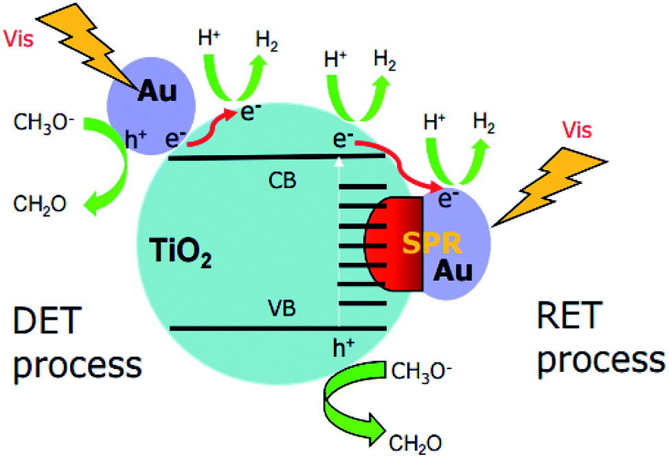 | ||
| Fig. 1 Two main proposed mechanisms for H2 production using Au–TiO2 in water/methanol mixtures under visible light illumination: direct electron transfer (DET) process (left); resonance energy transfer (RET) process (right). | ||
Therefore, the origin of the photoinduced electrons and the underlying mechanism upon visible light illumination remains unclear. Herein, we directly focus on the Au plasmon band, that is employing a 500 nm cutoff filter (≥500 nm) or using the 532 nm laser beam to totally get rid of the confusion caused by the direct excitation of TiO2.
2. Experimental section
Photocatalyst preparation
Au–TiO2 photocatalysts consisting of 1 wt% gold on TiO2 (Evonik Aeroxide P25) were prepared by the typical sol immobilization (labeled as SIM) method,4 which was conducted by adding an aqueous solution of poly vinyl alcohol (PVA) (1.2 mL, 1 wt% sol, Aldrich, >99%) to 1 mL HAuCl4·3H2O (0.05 M). A freshly prepared NaBH4 solution (2.5 mL, 0.1 M, Aldrich, >96%) was added dropwise to the above solution, with the color turning dark. After 30 min, the TiO2 support (1.0 g) was added and the suspension was further stirred for 12 h at 25 °C. Then, the suspension was centrifuged, washed three times with distilled water and dried for 12 h at 70 °C. The as-prepared samples were used for catalytic and spectroscopic experiments without any other treatment.Material characterization
The UV-Vis absorption spectra were recorded employing a UV-visible spectrophotometer (Varian Cary 100 Bio). TEM images were characterized by Transmission Electron Microscopy (TEM) (FEI Tecnai G2 F20 TMP) using a 200 kV field emission gun (FEG). XRD patterns were monitored using a Bruker D8 Advance X-ray Diffraction system.Photocatalytic H2 evolution test
The photocatalytic hydrogen production experiments were conducted under argon atmosphere in a double-wall quartz glass reactor, with a cooling system (Julabo) maintaining the temperature at 20 °C. The 1 g L−1 photocatalyst suspensions were prepared by suspending Au (1 wt%)–TiO2 in methanol/water mixtures (volume ratio 1![[thin space (1/6-em)]](https://www.rsc.org/images/entities/char_2009.gif) :5). The suspension was sonicated for 30 min before being transferred into the reactor and flushed with argon for 15 min to remove gases dissolved in the suspension and to make sure that Ar remained in the headspace of the reactor. The argon gas rate was kept constant at 10 cm3 min−1 during the photocatalytic measurement and the inlet gas flow rate for QMS was 1 cm3 min−1. Before illumination, the system was stabilized in the dark for 1 h to get a stable baseline. Afterwards, the suspension was illuminated employing an Osram XBO 1000 W Xe-Lamp (Müller) equipped with a 420 nm/500 nm cutoff filter.
:5). The suspension was sonicated for 30 min before being transferred into the reactor and flushed with argon for 15 min to remove gases dissolved in the suspension and to make sure that Ar remained in the headspace of the reactor. The argon gas rate was kept constant at 10 cm3 min−1 during the photocatalytic measurement and the inlet gas flow rate for QMS was 1 cm3 min−1. Before illumination, the system was stabilized in the dark for 1 h to get a stable baseline. Afterwards, the suspension was illuminated employing an Osram XBO 1000 W Xe-Lamp (Müller) equipped with a 420 nm/500 nm cutoff filter.
Electron paramagnetic resonance (EPR) spectroscopy
EPR measurements were carried out with a MiniScope MS400 spectrometer (Magnettech GmbH, Germany). A 500 W Mercury-Lamp (Muller) equipped with an optical cutoff filter (GC420/GC500) enables the illumination in the UV-Vis and visible light region. For low temperature measurements (90 K), the samples were placed in X-Band standard EPR tubes (Wilmad, 2 mm, O.D.) and cooled with a commercial EPR cold finger quartz Dewar by applying liquid nitrogen. The g values were calculated with the formula hν = gβB0 (B0 – external magnetic field, β – Bohr magneton, ge – Landé g-factor) as described in the literature.4a The frequency was at around 9.42 GHz, and the B0 was varied between 305–365 mT.Laser flash photolysis spectroscopy
During the laser flash photolysis measurements the samples were excited with an Nd-YAG laser (Brilliant B, Quantel) and the spectra were monitored by a laser flash photolysis spectrometer (LKS 80, Applied Photophysics). The excitation wavelength was tuned to 420 nm by employing an Optical Parametric Oscillator (OPO) (MagicPRISM, OPOTEK Inc.). Together with the OPO the 3rd harmonic (355 nm) of the Brilliant B laser was used to generate the visible light pulses with 6 mm diameter and 6 ns pulse length. The 532 nm laser was supplied by the 2nd harmonic (532 nm) of the Brilliant B laser. All experiments were performed in diffuse reflectance mode, where the analyzing light (supplied by a 150 W xenon arc lamp) was focused onto the sample and the reflected light was guided through the monochromator into the detector (Hamamatsu R928 photomultiplier). The light level detected by the oscilloscope was kept at 100 mV for all measurements to compensate the wavelength dependant sensitivity. Furthermore, all examinations were conducted under N2 atmosphere and 12 shots were averaged for every transient. The energy density of the 420 nm and 532 nm laser beam was around 5 mJ cm−2 per shot, respectively. The transient absorption change in reflectance ΔJ was calculated from the absorbance values according to the literature,18 which also provides more detailed information about the set-up.Theoretical calculation details
All spin-polarized calculations of optimization and energy bands were performed by Cambridge Sequential Total Energy Package (CASTEP). Projected augmented wave (PAW) pseudopotential was used to describe core electrons and plane wave basis set with 380 eV to represent valance electrons. Exchange-correlation energy was approximated by Perdew–Burke–Ernzerhof (PBE) functional of the generalized gradient approximation (GGA). Since the majority of P25 is anatase, we chose it for calculation. The model for anatase TiO2 dominant (101) surface was represented with a 12 monolayer unit cell with a 15 Å vacuum slab. Au–TiO2 model was constructed with a two gold atom cluster, to get rid of multi isomers of Au clusters,19–21 and TiO2 (101) surface, with bottom six atomic layers fixed and upper six layers relax (ESI Fig. S4†). A 4 × 4 × 2 k-points girds was used to optimize anatase cell, 2 × 2 × 1 k-points girds was used for TiO2 (101) surface and Au–TiO2 optimization and energy bands calculation both. The optimized lattice values of anatase were 3.78 and 9.49 Å, close to experimental values (3.78 and 9.5 Å). To overcome the self-interaction error of GGA method, a Hubbard correction (DFT+U) of 8.3 eV was imposed on Ti d-states; a good qualitative description of the electronic was obtained (Fig. S5†) with 3.23 eV band gap for bulk and 3.43 eV for (101) surface. No correction was applied to gold.3. Results
Material characterization
Fig. 2 shows the transmission electron microscopy (TEM) image of Au–TiO2. As can be seen, the lighter particles are the TiO2 matrix and the darker particles are the Au nanoparticles. The TEM images of Au–TiO2 reveal that the Au nanoparticles are well deposited on the surface of TiO2 matrix exhibiting particle sizes between 5 nm and 10 nm. Besides, the contents of Au–TiO2 photocatalyst were analyzed by means of X-Ray Diffraction (XRD). Accordingly, in addition to the peaks of anatase TiO2 (JCPDS # 01-070-7347) and rutile TiO2 (JCPDS # 03-065-5714), the XRD pattern exhibited peaks for Au (JCPDS # 03-065-2870), as shown in Fig. S1.† Due to the low concentration, the peaks of Au are weak. However, no peaks for other impurities (e.g. carbon or PVA) were detected within the detection limit.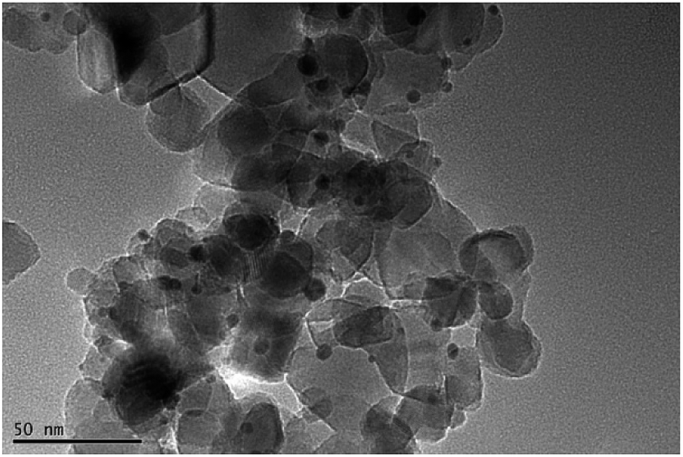 | ||
| Fig. 2 TEM image of Au (1 wt%)–TiO2. | ||
In this study, the optical properties of Au nanoparticles, bare TiO2 and Au–TiO2 were characterized by UV-Vis spectroscopy. As Fig. 3 shows Au-related samples exhibit plasmon band maxima located above 500 nm, namely Au nanoparticles with λmax at 520 nm, Au–TiO2 with λmax at 543 nm, respectively. The absorption edge of bare TiO2 is located around 400 nm, which is in good agreement with previous studies.4b Spectra of bare TiO2 and the employed filters are presented in the ESI Fig. S2.†
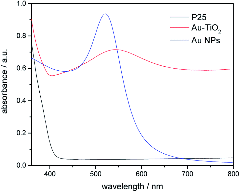 | ||
| Fig. 3 Diffuse-reflectance UV-Vis spectra of bare TiO2 (black), Au NPs (blue) and Au–TiO2 (red). | ||
Photocatalytic H2 evolution test
Fig. 4 presents the photocatalytic H2 evolution rates from CH3OH/H2O mixtures obtained employing Au-loaded TiO2 under visible-light illumination in the presence of a 500 nm cutoff filter. However, no formation of H2 was detected for bare TiO2 photocatalyst within the detection limit under the same reaction condition. In comparison to bare TiO2, Au–TiO2 exhibited H2 production ability upon visible light illumination in the presence of a 500 nm cutoff filter, indicating that Au-SPR can directly lead to photocatalytic H2 production.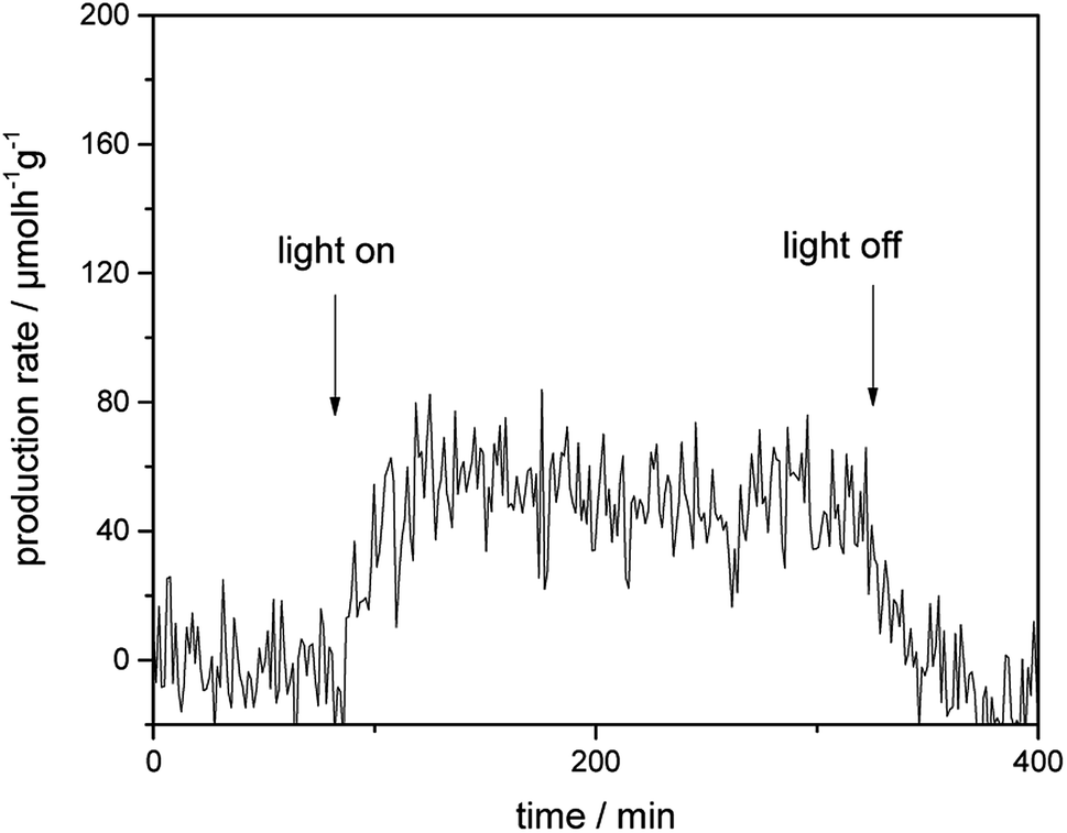 | ||
| Fig. 4 Photocatalytic H2 evolution rate of Au–TiO2 obtained from CH3OH/H2O mixtures upon visible light illumination in the presence of a 500 nm cutoff filter. | ||
EPR analysis
The photoinduced EPR signals of trapped electrons and holes for bare TiO2 and Au–TiO2 were recorded in Ar at 90 K by (applying liquid nitrogen). The EPR parameters of the detected signals and their assignments were presented (ESI Fig. S3 and Table S1†), which are in good agreement with the previous literatures.4,22–24In the presence of a 500 nm cutoff filter, when comparing the EPR signals of bare Au–TiO2 obtained in the dark with those observed upon visible light illumination (≥500 nm), small but clear signal of trapped electrons (anatase Ti3+ at g = 1.990) was observed (see Fig. 5), indicating the photo-induced electrons were trapped in TiO2.
 | ||
| Fig. 5 EPR spectra of Au–TiO2 obtained in the dark and under visible light illumination (≥500 nm) at 90 K. | ||
Laser flash photolysis analysis
Fig. 6 shows the transient absorption signals measured at 400 nm and 680 nm for bare TiO2 and Au–TiO2 in the absence of any electron acceptor or donor. From the literature, it is known that Ti3+ species absorb in the wavelength range around 680 nm,25a while the signal of the trapped holes can be monitored at 400–550 nm.25b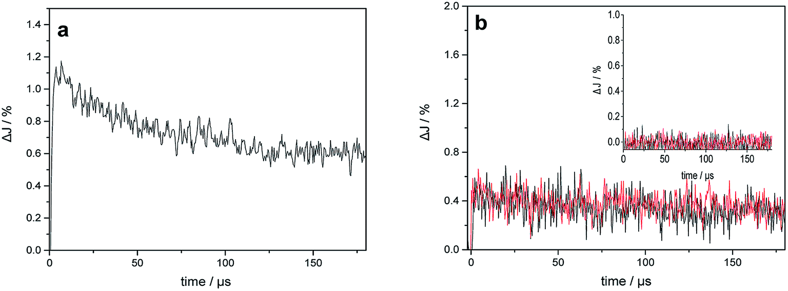 | ||
| Fig. 6 (a) Transient absorption signals of bare TiO2 observed at 680 nm upon 420 nm laser excitation; (b) transient absorption signals of bare TiO2 (inset) and Au–TiO2 observed at 680 nm (black) and 400 nm (red) upon 532 nm laser excitation in a N2 atmosphere. | ||
As shown in Fig. 6a, the transient signal of the trapped electron in TiO2 was detected indicating that bare TiO2 can be directly excited by 420 nm laser beam. The decay of the transient signals can be related to the internal electron/hole recombination.18,25 Upon 532 nm laser excitation, which is the plasmon band of the Au NPs, in addition to the transient absorption signal of the trapped electrons at 680 nm, the signal of the trapped holes in TiO2 (see Fig. 6b) was monitored at 400 nm. As expected, no transient signals were observed for bare TiO2 in the blank experiment (see Fig. 6b inset). The trapped holes observed at 400 nm exhibit nearly the same transient signal intensity and kinetic like the trapped electrons detected at 680 nm.
DFT calculation analysis
To further analyze the enhanced photocatalytic activities of Au–TiO2, the electronic structure of Au–TiO2 system were calculated, showed in Fig. 7. As shown in Fig. 7a, energy levels of the system are apparently split due to the reduction of symmetry and the existence of surface dangling bonds. Moreover, new energy levels are appeared, two near the top of valence band and bottom of conduction band each, and four near Fermi level. Meanwhile, Fig. 7 presented clear evidence that new isolated impurity energy levels are mainly attributed to d orbitals of Au clusters, and the top of valence band by the hybrid orbitals of Au and TiO2 surface.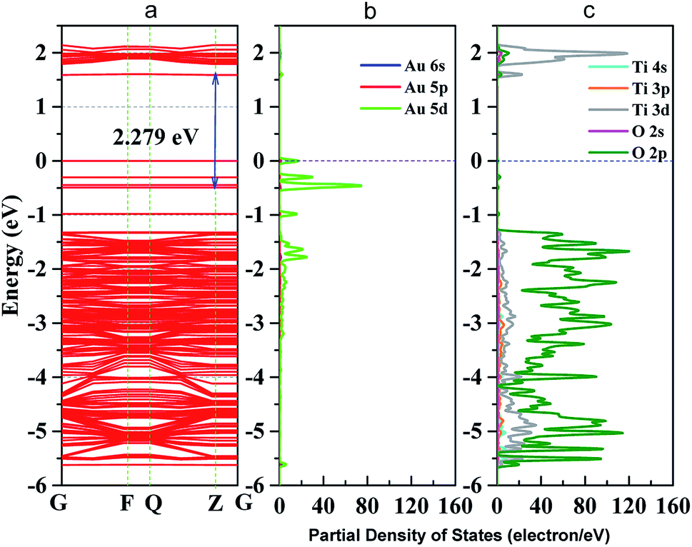 | ||
| Fig. 7 (a) band structure of Au–TiO2 slab; (b) partial density of states (PDOS) of Au cluster; (c) PDOS of TiO2 (101) surface; blue dot line represents Fermi level. | ||
4. Discussion
Obviously, Au–TiO2 can produce H2 upon visible light illumination (employing a 500 nm cutoff filter). However, bare TiO2 absorbs no light in the wavelength range above 500 nm and no H2 can be formed (≥500 nm) as evidenced by blank experiments. Besides, the XRD pattern showed no other impurities (e.g. carbon or PVA) were detected within the detection limit. Hence, it can be excluded that the visible-activity of Au–TiO2 above 500 nm is caused by a carbon radical stem from polyvinyl alcohol remaining in the catalyst from the synthesis. The observation of any H2 and signals of trapped electrons and holes can only be related to the Au-SPR effect. As shown in Fig. S3,† the appearance of new EPR signals can be observed upon illumination (≥500 nm) which can be attributed to trapped electrons and trapped holes according to the literature.4,22–24 The new formed EPR signals indicate the excitation of Au–TiO2 photocatalyst upon visible light illumination above 500 nm. However, as new formed EPR signals are indistinctive (especially the signals at g = 2.002–2.005 (ref. 4 and 22−24)) laser excitation was employed to totally get rid of the confusion caused by the proximity of g values for signals of trapped electrons and trapped holes.Upon 532 nm laser (∼2.34 eV) excitation, the transient signals of the trapped electrons and holes in TiO2 were also observed, which further confirmed the presence of photogenerated electrons and holes. It should be noted here that, the transient signals of the Au-SPR induced electrons can be detected in ps scale14 and most charges recombine within 1 ns.26,27 Therefore, the significant decay process of the transient signals in Fig. 6b was not observed within the detection time scale. In the absence of any electron acceptor or donor, transient signals of the trapped electrons and holes in TiO2 can be observed on longer time scale (μs), as presented. The long-lived charges can be correlated with the photocatalytic activity of the photocatalysts.28,29
It should be emphasized here that the energy of the incoming photons (λ ≥ 500 nm, Ehν ≤ 2.48 eV) is insufficient to excite the electrons from the valence band to the conduction band of TiO2 and leave the holes in the valence band of TiO2. However, due to the Au-SPR, many electrons in Au have higher energy than the conduction band of TiO2, facilitating the electron injection from Au to the conduction band of TiO2.13,30 This provided a reasonable explanation for the observation of the Ti3+ in both EPR spectroscopy and laser flash photolysis spectroscopy. As reported,13,30 the direct electron injection process is thermodynamically favorable, since the photon energy (hν) only needs to overcome the gap between the Fermi level (Ef) of Au and the top of TiO2 conduction band (ECB), that is: hν ≥ ECB0 – Ef. Moreover, after the contact of Au and TiO2, the Fermi level of the Au nanoparticles will be equalized to the work function and the conduction band of TiO2 will be bent down.30 Therefore, the trapped electrons leading to the formation of Ti3+ are from the “hot electron injection” of the Au nanoparticles, process II (a) in Fig. 8.
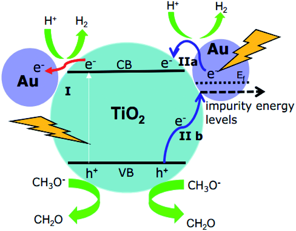 | ||
| Fig. 8 Proposed mechanisms for H2 production using Au–TiO2 in water/methanol mixtures upon visible light illumination (≥420 nm: process I + II; ≥500 nm: process II). | ||
On the other hand, since no holes can be transferred from the Au nanoparticles to the valence band of TiO2, the EPR signals of the trapped holes in TiO2 (signal D) can only originate from the Au-SPR initiated electron–hole pair generation in TiO2. However, it should be noted here again that the energy of the visible light (≥500 nm, i.e., ≤2.5 eV) is not sufficient to overcome the band gap energy of TiO2. In this case, it is assumed that the Au-SPR initiates the Interfacial Charge Transfer (IFCT), as proposed by Creutz.31 Accordingly, electrons in the valence band of TiO2 directly transfer to the surface Au clusters, that is not via the excited state,32 while the holes are trapped in the valence band of TiO2, process II (b) in Fig. 8. Besides, after electrons injection from Au to the conduction band of TiO2, monovalent of Au might be generated. Therefore, the DET process also provides the possibility of interfacial charge transfer from valence band of TiO2 to monovalent of Au.
Moreover, the obtained theoretical calculation results provide further evidences supporting the above proposed mechanisms. Firstly, a good qualitative description of the electronic was obtained (Fig. S5†) with 3.23 eV band gap for bulk and 3.43 eV for (101) surface. As presented above (Fig. 7), with the deposition of Au clusters on the surface of TiO2, new isolated impurity energy levels appeared mainly due to d orbitals of Au clusters. Therefore, the possibility of electron transfer from Au to the conduction band of TiO2 is demonstrated by DFT calculation. Besides, the existence of Au impurity energy levels in band gap also provide channels for electrons to be excited with lower energy (λ ≥ 500 nm, Ehν ≤ 2.48 eV). Moreover, the maxima absorption wavelength of Au–TiO2 in Fig. 3 (543 nm, 2.288 eV) is in good accordance with the energy difference between an impurity level and the bottom of conduction band in DFT result (2.279 eV). Furthermore, due to the small energy gaps, the electron transfer from the valence band of TiO2 to the surface loaded Au clusters is thermodynamically feasible, as proposed by IFCT process. Herein, the proposed mechanisms based on the experimental data are favored by the DFT calculation results. In case of the electron transfer processes can occur employing pure anatase as TiO2 source, the same process should be easier in the case of using the mixture of anatase and rutile TiO2, for example, in Evonik Aeroxide P25 as TiO2 source.
Besides, the EPR and the laser flash photolysis spectra (ESI Fig. S3† and 6a) show clear evidence that bare TiO2 (P25) can be directly excited by visible light illumination (λ ≥ 420 nm) or 420 nm laser beam (process I in Fig. 8), which has long been ignored by some studies. Therefore, the investigation of SPR influence on the visible light photocatalytic activity of TiO2 employing a 400/420 nm cutoff filter does not seem to be correct. Actually, upon visible light illumination (λ ≥ 420 nm), the direct excitation of TiO2 and the SPR-induced excitation can both lead to the visible light photocatalytic activity of Au–TiO2, process I + II in Fig. 8.
Therefore, upon illumination above 500 nm, due to the Au-SPR, electrons can be directly injected into the conduction band of TiO2, as reported previously.4a,10,13,14,26 Simultaneously, the Au-SPR can also initiate electron hole pair generation in TiO2, while the electrons directly transfer from the valence band of TiO2 to the surface Au-related species (IFCT process). The two pathways cooperatively contribute to the SPR-induced visible-driven photocatalytic H2 production ability of Au–TiO2 photocatalyst. This also provides a reasonable explanation for the photocatalytic activity when the plasmonic metal nanoparticles were homogeneously covered with an insulating SiO2 shell.
5. Conclusions
In conclusion, Au-SPR driven photocatalytic H2 production was observed upon visible light illumination (≥500 nm). Direct experimental evidences were presented that Au nanoparticles can transfer the SPR-induced hot electrons into the conduction band of TiO2 upon visible light illumination in the wavelength range above 500 nm. Simultaneously, the Au-SPR can also initiate electron–hole pair generation in TiO2. However, due to the photons energy/ESPR is insufficient to overcome the band gap of TiO2, the initiated electrons directly transfer to the surface Au-related species through the IFCT process rather than via the excited state. The experimental results are in good agreement with the data obtained from DFT calculation. The DFT calculation analysis clearly shows how the d orbitals of Au clusters create impurity energy levels and decrease the band gap of Au–TiO2. We are optimistic that our contribution may contribute to the controversial discussion about the origin of the SPR- induced electron formation within Au–TiO2 thus providing a new horizon for further investigations on exploring more effective visible light harvesting photocatalysts for solar energy conversion.Conflicts of interest
There are no conflicts to declare.Acknowledgements
Financial Support from the China Scholarship Council is gratefully acknowledged. The authors would like to thank the LNQE for TEM measurements. J. S. and D. B. kindly acknowledge financial support from the Federal Ministry of Education and Research (BMBF) for the project “DuaSol” (03SF0482C). F. S. and D. B. kindly acknowledge financial support from the Federal Ministry of Education and Research (BMBF) for the project “PureBau” (13N13350).References
- J. A. Turner, Science, 1999, 285, 687–689 CrossRef PubMed.
- A. Kudo and Y. Miseki, Chem. Soc. Rev., 2009, 38, 253–278 RSC.
- S. K. Cushing, J. Li, F. Meng, T. R. Senty, S. Suri, M. Zhi, M. Li, A. D. Bristow and N. Wu, J. Am. Chem. Soc., 2012, 134, 15033–15041 CrossRef PubMed.
- (a) J. B. Priebe, M. Karnahl, H. Junge, M. Beller, D. Hollmann and A. Brückner, Angew. Chem., Int. Ed., 2013, 52, 11420–11424 CrossRef PubMed; (b) J. B. Priebe, J. Radnik, A. J. J. Lennox, M. Pohl, M. Karnahl, D. Hollmann, K. Grabow, U. Bentrup, H. Junge, M. Beller and A. Brückner, ACS Catal., 2015, 5, 2137–2148 CrossRef.
- L. Liu, T. D. Dao, R. Kodiyath, Q. Kang, H. Abe, T. Nagao and J. Ye, Adv. Funct. Mater., 2014, 24, 7754–7762 CrossRef.
- M. Murdoch, G. I. N. Waterhouse, M. A. Nadeem, J. B. Metson, M. A. Keane, R. F. Howe, J. Llorca and H. Idriss, Nat. Chem., 2011, 3(6), 489–492 CrossRef PubMed.
- Y. C. Pu, G. M. Wang, K. D. Chang, Y. C. Ling, Y. K. Lin, B. C. Fitzmorris, C. M. Liu, X. H. Lu, Y. X. Tong, J. Z. Zhang, Y. J. Hsu and Y. Li, Nano Lett., 2013, 13, 3817–3823 CrossRef PubMed.
- J. W. Hong, D. H. Wi, S.-U. Lee and S. W. Han, J. Am. Chem. Soc., 2016, 138, 15766–15773 CrossRef PubMed.
- A. Stevanovic, M. Büttner, Z. Zhang and J. T. Yates, J. Am. Chem. Soc., 2012, 134(1), 324–332 CrossRef PubMed.
- C. G. Silva, R. Juárez, T. Marino, R. Molinari and H. García, J. Am. Chem. Soc., 2011, 133, 595–602 CrossRef PubMed.
- (a) D. B. Ingram and S. Linic, J. Am. Chem. Soc., 2011, 133, 5202–5205 CrossRef PubMed; (b) S. Linic, P. Christopher and D. B. Ingram, Nat. Mater., 2011, 10, 911–921 CrossRef PubMed.
- Z. W. Seh, S. Liu, M. Low, S. Y. Zhang, Y. Liu, Z. Liu, A. Mlayah and M.-Y. Han, Adv. Mater., 2012, 24, 2310–2314 CrossRef PubMed.
- K. Qian, B. C. Sweeny, A. C. Johnston-Peck, W. Niu, J. O. Graham, J. S. DuChene, J. Qiu, Y.-C. Wang, M. H. Engelhard, D. Su, E. A. Stach and W. D. Wei, J. Am. Chem. Soc., 2014, 136, 9842–9845 CrossRef PubMed.
- Z. Bian, T. Tachikawa, P. Zhang, M. Fujitsuka and T. Majima, J. Am. Chem. Soc., 2014, 136, 458–465 CrossRef PubMed.
- K. Awazu, M. Fujimaki, C. Rockstuhl, J. Tominaga, H. Murakami, Y. Ohki, N. Yoshida and T. Watanabe, J. Am. Chem. Soc., 2008, 130, 1676–1680 CrossRef PubMed.
- Z. Liu, W. Hou, P. Pavaskar, M. Aykol and S. B. Cronin, Nano Lett., 2011, 11(3), 1111–1116 CrossRef PubMed.
- S. Zhu, S. Liang, Q. Gu, L. Xie, J. Wang, Z. Ding and P. Liu, Appl. Catal., B, 2012, 119–120, 146–155 CrossRef.
- J. Schneider, K. Nikitin, M. Wark, D. W. Bahnemann and R. Marschall, Phys. Chem. Chem. Phys., 2016, 18, 10719–10726 RSC.
- K. Z. Milowska and J. K. Stolarczyk, Phys. Chem. Chem. Phys., 2016, 18(18), 12716–12724 RSC.
- L. A. Mancera and D. M. Benoit, Phys. Chem. Chem. Phys., 2016, 18(1), 529–549 RSC.
- L. A. Mancera and D. M. Benoit, Comput. Theor. Chem., 2015, 1067, 24–32 CrossRef.
- D. C. Hurum, A. G. Agrios, K. A. Gray, T. Rajh and M. C. Thurnauer, J. Phys. Chem. B, 2003, 107, 4545–4549 CrossRef.
- (a) T. Hirakawa, H. Kominami, B. Ohtani and Y. Nosaka, J. Phys. Chem. B, 2001, 105, 6993–6999 CrossRef; (b) C. P. Kumar, N. O. Gopal, T. C. Wang, M.-S. Wong and S. C. Ke, J. Phys. Chem. B, 2006, 110, 5223–5229 CrossRef PubMed.
- V. Jovic, K. E. Smith, H. Idriss and G. I. N. Waterhouse, ChemSusChem, 2015, 8, 2551–2559 CrossRef PubMed.
- (a) D. W. Bahnemann, M. Hilgendorff and R. Memming, J. Phys. Chem. B, 1997, 101, 4265–4275 CrossRef; (b) A. O. T. Patrocinio, J. Schneider, M. D. França, L. M. Santos, B. P. Caixeta, A. E. H. Machado and D. W. Bahnemann, RSC Adv., 2015, 5, 70536–70545 RSC.
- A. Furube, L. Du, K. Hara, R. Katoh and M. Tachiya, J. Am. Chem. Soc., 2007, 129, 14852–14853 CrossRef PubMed.
- L. Du, A. Furube, K. Yamamoto, K. Hara, R. Katoh and M. Tachiya, J. Phys. Chem. C, 2009, 113(16), 6454–6462 CrossRef.
- J. S. DuChene, B. C. Sweeny, A. C. Johnston-Peck, D. Su, E. A. Stach and W. D. Wei, Angew. Chem., Int. Ed., 2014, 53, 7887–7891 CrossRef PubMed.
- (a) Z. Bian, T. Tachikawa, T. Majima and J. Phys, Chem. Lett., 2012, 3, 1422–1427 Search PubMed; (b) Z. Bian, T. Tachikawa, W. Kim, W. Choi and T. Majima, J. Phys. Chem. C, 2012, 116, 25444–25453 CrossRef.
- X. Zhang, Y. L. Chen, R. Liu and D. P. Tsai, Plasmonic Photocatalysis, Rep. Prog. Phys., 2013, 76, 046401–046441 CrossRef PubMed.
- (a) C. Creutz, B. S. Brunschwig and N. Sutin, J. Phys. Chem. B, 2005, 109, 10251–10260 CrossRef PubMed; (b) C. Creutz, B. S. Brunschwig and N. Sutin, J. Phys. Chem. B, 2006, 110, 25181–25190 CrossRef PubMed.
- (a) H. Irie, K. Kamiya, T. Shibanuma, S. Miura, D. A. Tryk, T. Yokoyama and K. Hashimoto, J. Phys. Chem. C, 2009, 113, 10761–10766 CrossRef; (b) H. Yu, H. Irie, Y. Shimodaira, Y. Hosogi, Y. Kuroda, M. Miyauchi and K. Hashimoto, J. Phys. Chem. C, 2010, 114, 16481–16487 CrossRef.
Footnote |
| † Electronic supplementary information (ESI) available: Spectra of the employed filters and EPR spectra of bare TiO2 obtained under different conditions as well as the assignments of the EPR signals. XRD pattern of Au–TiO2. Side and top view of Au–TiO2 model. Band structure of bulk anatase, (101) surface and partial density of states of TiO2 (101) surface. See DOI: 10.1039/c8ra05450a |
| This journal is © The Royal Society of Chemistry 2018 |