 Open Access Article
Creative Commons Attribution 3.0 Unported Licence
Preparation of a MoS2/carbon nanotube composite as an electrode material for high-performance supercapacitors†
Xiaobo Chen *a,
Jingguo Dinga,
Jing Jianga,
Guoce Zhuanga,
Zhihai Zhanga and
Peizhi Yang*b
aSchool of New Energy and Electronic Engineering, Yancheng Teachers University, Yancheng, 224051, P. R. China. E-mail: chenxbok@126.com
bKey Laboratory of Education Ministry for Advance Technique and Preparation of Renewable Energy Materials, Institute of Solar Energy, Yunnan Normal University, Kunming, 650500, P. R. China. E-mail: pzhyang@hotmail.com
First published on 20th August 2018
Abstract
MoS2 and MoS2/carbon allotrope (MoS2/C) composites for use as anodes in supercapacitors were prepared via a facile hydrothermal method. In this study, we report the effects of various carbon-based materials (2D graphene nanosheet (GNS), 1D carbon nanotube (CNT), and 0D nano carbon (NC)) on the electrochemical performances. Among all nanocomposites studied, MoS2/CNT exhibited the best electrochemical performance. Specifically, the MoS2/CNT composite exhibits remarkable performances with a high specific capacitance of 402 F g−1 at a current density of 1 A g−1 and an outstanding cycling stability with 81.9% capacitance retention after 10![[thin space (1/6-em)]](https://www.rsc.org/images/entities/char_2009.gif) 000 continuous charge–discharge cycles at a high current density of 1 A g−1, making it adaptive for high-performance supercapacitors. The superiority of MoS2/CNT was investigated by field emission scanning electron microscopy and transmission electron microscopy, which showed that MoS2 nanosheets were uniformly loaded into the three-dimensional interconnected network of nanotubes, providing an excellent three dimensional charge transfer network and electrolyte diffusion channels while effectively buffering the collapse and aggregation of active materials during charge–discharge processes. Overall, the MoS2/CNT nanocomposite synthesized by a simple hydrothermal process presents a new and promising candidate for high-performance anodes for supercapacitors.
000 continuous charge–discharge cycles at a high current density of 1 A g−1, making it adaptive for high-performance supercapacitors. The superiority of MoS2/CNT was investigated by field emission scanning electron microscopy and transmission electron microscopy, which showed that MoS2 nanosheets were uniformly loaded into the three-dimensional interconnected network of nanotubes, providing an excellent three dimensional charge transfer network and electrolyte diffusion channels while effectively buffering the collapse and aggregation of active materials during charge–discharge processes. Overall, the MoS2/CNT nanocomposite synthesized by a simple hydrothermal process presents a new and promising candidate for high-performance anodes for supercapacitors.
1. Introduction
There has been an ever-increasing and urgent demand for developing renewable energy resources and electrical energy storage technologies in response to the increasing issues of environmental pollution and energy consumption. Among various energy storage devices, supercapacitors (SCs) are considered as one of the most promising devices for energy storage due to high power density, high energy density, long lifespan, quick charging/discharging.1 There are three factors that are most commonly considered in performance assessment of SCs: electrode material, electrolyte and SCs device architecture.2 Among which, the electrode material plays an important role in determining the performance of SCs, so it is still very attractive to develop and design a novel electrode material with prominent electrochemical properties.Two-dimensional (2D) layered MoS2 nanosheets may perform best for applications in electrochemical energy storage because of their large surface area and exposed active sites.3,4 Several recent reports have been focused on the supercapacitor performance of pure MoS2 with diverse morphologies. For examples, Huang et al. reported that MoS2 nanosheets as electrode materials exhibited a specific capacitance up to 129.2 F g−1 at 1 A g−1 with capacitance retention of 85.1% after 500 cycles;5 Wang et al. prepared flower-like MoS2 which showed a specific capacitance of 168 F g−1 at a current density of 1 A g−1 when applied as electrode materials for electrochemical capacitors.6 These results indicate that MoS2 is a promising electrode material for supercapacitors owing to its two-dimensional sheets-like morphology, which can provide large surface area for double-layer charge storage. In addition, the easy diffusion of electrolyte into the inner region (interlayers) of the MoS2 electrode at lower scan rates can provide faradaic capacitance, which acts a good part in improved charge storage capability.7 These studies on the supercapacitive properties of pure MoS2 showed only moderate performance as an electrode material due to the relatively poor electronic conductivity and stability. Therefore, the electrochemical properties of MoS2 can be improved via making composites with other electroactive materials, such as carbon allotrope materials and conductive polymer to overcome the above problem.4,7–10 Various kinds of carbon materials have been suggested as conductivity supporters (or additives) for MoS2, such as nano carbon black,10–12 graphene,3,4,13 and carbon nanotube.8,14,15 However, up to present, the comparative investigation about the effect of carbon supporters on the electrochemical performance for supercapacitor application is still rarely reported.
Herein, to combine all these merits and enhance the electrochemical performance of MoS2, a straightforward hydrothermal method has been developed in this work to synthesize MoS2/NC, MoS2/G and MoS2/CNT composites through hydrothermal method. The morphology, surface areas, porous structures and electrochemical properties of as-prepared MoS2/NC, MoS2/G and MoS2/CNT composites had been studied comparatively.
2. Experimental
2.1. Material synthesis
In this work, graphene nanosheets (GNSs), carbon nanotubes (CNT) and nano carbon black (NCB) are purchased from Tanfeng Tech. Inc (Suzhou, China). Other reagents are analytical grade without further purification and purchased from Zhanyun Chemical Co., Ltd., Shanghai, China.MoS2/C composites (MoS2/NC, MoS2/G and MoS2/CNT) were prepared through hydrothermal method. Firstly, 30 mg carbon based nanomaterials (NC, G, or CNT) were firstly blended with 20 mL ethanol and ultrasonicated for 1 h to obtain a solution A (carbon based nanomaterials dispersion). Secondly, 1 mmol Na2MoO4·2H2O and 5 mmol thiourea were dissolved in 60 mL of DI water and added to the above dispersion and stirred for 1 h. The reaction mixture was then transferred into a Teflon-lined autoclave, heated up to 210 °C, and maintained at this temperature for 24 h. The resultant black precipitate was centrifuged, washed three times with DI water, followed by ethanol washing, and dried under vacuum. For comparison, the pure MoS2 was also prepared via the same method without carbon.
2.2. Materials characterizations
The crystallographic structure was characterized by X-ray diffraction (XRD) on an X-ray powder diffractometer (Smartlab-9 X-ray diffractometer, Rigaku, Japan) using Cu Kα radiation (λ = 1.5418 Å). The specific surface areas (BET method) and porous structures measurements were performed in a model ASAP 2020 Micromeritics apparatus at 77 K. Field emission scanning electron microscopic (FESEM) images were carried out by Zeiss Supra 35VP, transmission electron microscopic (TEM) and high-resolution transmission electron microscopic (HRTEM) images were observed by FEI Tecnai F20.The electrodes were obtained by mixing active material (85 wt%), acetylene black (10 wt%) and polytetrafluoroethylene (PTFE, 60 wt% dispersion in water) binder (5 wt%). Then, it was dried in hot air oven at 80 °C for 0.5 h, and pressed under the pressure of 10 MPa and finally dried at 100 °C for 12 h. Each electrode contained about 5 mg of active material.
2.3. Electrochemical measurements
The electrochemical properties were tested using three-electrode system with the working electrode, Pt counter electrode and Hg/HgO electrode as the reference electrode in the 1 M Na2SO4 aqueous solution at room temperature. Cyclic voltammetry (CV) measurements were performed on a CHI660E electrochemical workstation (CHI, Shanghai China) and galvanostatic charge–discharge (GCD) curves were measurements by a Neware battery testing workstation (Neware, Shengzhen China). Electrochemical impedance spectroscopy (EIS) was performed on the electrochemical work-station (CHI660D) by applying an ac amplitude of 0.5 mV in the frequency from 106 to 10−2 Hz.3. Result and discussion
3.1. Structure characterizations
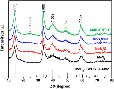
Fig. 1 shows XRD patterns of pure MoS2 and MoS2/NC, MoS2/G and MoS2/CNT composites. From the XRD pattern of as-prepared MoS2 nanosheets, the peaks of 14.4°, 32.7°, 39.5° and 58.3° are in good accordance with the standard values of MoS2 (JCPDS card no. 37-1492). In terms of MoS2/NC, MoS2/G and MoS2/CNT composites, a broad diffraction hump between 21° and 27° could be attributed to the (002) reflection of a graphitic structure, suggesting the existence of carbon-based materials. In addition, no characteristic peaks of other impurities have been detected, implying that the MoS2 and MoS2/NC, MoS2/G and MoS2/CNT composites are of high purity.3.2. Morphology characterizations
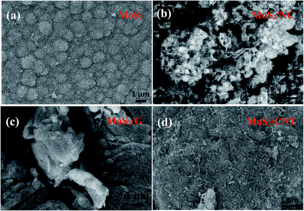
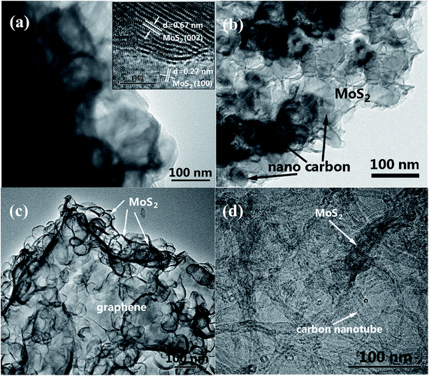
The shape and morphology of the hydrothermally synthesized samples were investigated by SEM and TEM images. The distinctive FE-SEM morphologies of MoS2, MoS2/NC, MoS2/G and MoS2/CNT are displayed in Fig. 2 and S2.† The FE-SEM micrograph of pure MoS2 (Fig. 2(a)) suggested that few layered 2D MoS2 hierarchical nanosheets are aggregated to form microspheres with the size of 1 μm. The MoS2/NCs show a nanoflower structure (Fig. 2(b)). There is no agglomeration of free nano carbon particles in the composite, implying nano carbon particles are intercalated in the interlayers of the MoS2 nanosheets. Fig. 2(c) shows the SEM image of the MoS2/G. It can be observed that the graphene nanosheets are decorated randomly with MoS2 nanosheets. Incorporation of CNTs can effectively reduce the stacking and yield highly separated ultrathin MoS2 nanosheets (Fig. 2(d)), which are later determined by TEM. More importantly, the relatively long CNTs form interconnected network to facilitate the fast electron transport. It is clearly observed that CNTs interweaved with MoS2 nanosheets. This unique architecture is anticipated to dramatically increase the electronic conductivity and maintain structural integrity thus to boost the rate performance and cycling stability in supercapacitor applications.As shown in Fig. 3(a), the TEM image of MoS2 forms two-dimensional nanosheets. The high-resolution TEM (HRTEM) image in the inset of Fig. 3(a) indicates the lattice figure with interlayer spacing of 0.67 nm which corresponds to the (002) plane of MoS2.16 Also, the lattice spacing of 0.27 nm which belongs to the (100) plane of MoS2 can be observed in the same image.17 SEM image of MoS2/NC (Fig. 3(b)) displays that the MoS2 shell coats nano carbon tightly. It can be also seen that GS are decorated randomly by MoS2 nanosheets to generate MoS2/G composite in Fig. 3(c). Fig. 4(d) shows more evidence of the extreme porous nature of the nanohybrid composed of ultrathin MoS2 nanosheets supported/separated by CNTs.
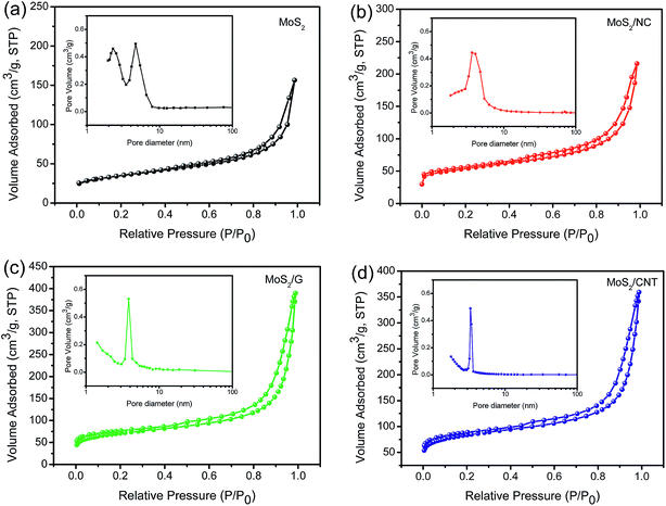 | ||
| Fig. 4 The N2 adsorption–desorption isotherms of MoS2 (a), MoS2/NC (b), MoS2/G (c) and MoS2/CNT composites (d). The insets show corresponding pore size distributions. | ||
Furthermore, the synthesized MoS2/CNT was also characterized by EDS. From Fig. S1(a),† the signals of C, O, S and Mo elements can be seen. From the observation of the four element mappings of Mo, S, C and O (Fig. S1(b)†), the elements are uniformly distributed throughout the MoS2/CNT composite. Therefore, the HRTEM and EDS results indicated that the MoS2/carbon hybrid has been successfully synthesized.
Fig. 4 shows the N2 adsorption–desorption isotherms and corresponding pore size distribution curves of samples. The isotherms of as-prepared materials all exhibit the type IV hysteresis loop as defined by IUPAC. The BET surface areas of the MoS2, MoS2/NC, MoS2/G and MoS2/CNT are 116, 219, 236 and 275 m2 g−1, respectively. Obviously, the surface area of MoS2/CNT is 2.4 times as much as pure MoS2, attributing to the compact interconnected network structure, which not only provides large surface area for charge storage but also facilitates electrolyte penetration through the mesopores. The pore size distributions of these samples are shown in the insets, confirming that the samples have mesoporous characteristics. The well-developed 3D interconnected porous network with multilevel pores can provide not only favorable transport channels for electrolyte but also strong mechanical strength. Based on the above mentioned merits, the MoS2/CNT composite can be employed as an excellent electrode material for SCs and the detailed electrochemical measurements are performed as follows.
3.3. Electrochemical performances
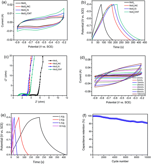
Both CV and GCD measurements are carried out to survey the electrochemical properties. As shown in Fig. 5(a), the CV curves of MoS2 and MoS2/NC, MoS2/G and MoS2/CNT composites are performed within a potential window from 0.9 to 0.2 V at a scanning rate of 10 mV s−1 in 1 M Na2SO4. The measured voltammograms of MoS2 and MoS2/NC, MoS2/G and MoS2/CNT show quasi-rectangular shapes with a pair of small humps at ca. −0.6 V and ca. −0.4 V, which represent intercalation and expulsion of Na+ ions between the MoS2 layers and can be represented as follows:3| MoS2 + Na+ + e− ⇌ MoS − SNa | (1) |
The output current of MoS2/CNT is larger than those of MoS2 and MoS2/NC and MoS2/G. One major weakness of pure MoS2 based SCs is its inherent resistivity.3,4 The results indicate that the conductivity of MoS2 can be improved by combining MoS2 and CNT together to form composites, meanwhile, the specific capacitance also increases. Fig. 5(b) shows the GCD curves of MoS2 and MoS2/NC, MoS2/G and MoS2/CNT at a current density of 1 A g−1 with voltage between −0.9 and −0.4 V. It is clear that the discharge time of MoS2/CNT is much longer compared to MoS2, MoS2/NC and MoS2/G. The specific capacitances can be calculated using the eqn (2):
| Cs = I × Δt/(m × ΔV) | (2) |
CV measurement is carried out to further investigate the charge storage mechanism of MoS2/CNT in the three electrode system. Fig. 5(d) shows CV curve area of MoS2/CNT increases with increasing scan rates (from 2 to 100 mV s−1). The CV loop of MoS2/CNT electrode at 100 mV s−1 is still close to rectangular, suggesting that the MoS2/CNT composite can be employed as an excellent electrode material. It should be emphasized that the curves for the initial cycles at lower scan rates exhibit faradaic capacitance in addition to electric double layer capacitance, due to diffusion of the ions into the MoS2 interlayers at low scan rates,19 improving charge storage capabilities. The specific capacitances of the MoS2/CNT calculated from the GCD curves (Fig. 5(e)) are 402, 292, 215 and 172 F g−1 at current densities of 1, 2, 5 and 10 A g−1, respectively. Since such a decrease of specific capacitances is common with increasing scan rates, and caused by the difficulty of ion diffusion and the insufficient faradaic redox reaction at high scan rates.4
The cycle stability of MoS2/CNT composite is important for its practical applications. The cycling performance of MoS2/CNT at a current density of 1 A g−1 was shown in Fig. 5(f). Importantly, the specific capacitance still maintains 81.9% level after 10![[thin space (1/6-em)]](https://www.rsc.org/images/entities/char_2009.gif) 000 consecutive cycles. Particularly, there is no clear capacitance drop occurred over 1000 cycles (99.6% retention) due to the support between CNT and MoS2 nanosheets, presenting excellent cycling stability of MoS2/CNT. More interestingly, compared with other MoS2/carbon composites with electrolyte of 1 M Na2SO4, MoS2/CNT showed higher specific capacitance and more excellent electrochemical stability than those of most reported MoS2/carbon composite electrode (Table 1). The electrochemical reversibility can be further explained by EIS measurements (Fig. S3†). Noticeably, the EIS spectra are similar in terms of the curve shape except that a moderate change of equivalent series resistance. Before and after 10
000 consecutive cycles. Particularly, there is no clear capacitance drop occurred over 1000 cycles (99.6% retention) due to the support between CNT and MoS2 nanosheets, presenting excellent cycling stability of MoS2/CNT. More interestingly, compared with other MoS2/carbon composites with electrolyte of 1 M Na2SO4, MoS2/CNT showed higher specific capacitance and more excellent electrochemical stability than those of most reported MoS2/carbon composite electrode (Table 1). The electrochemical reversibility can be further explained by EIS measurements (Fig. S3†). Noticeably, the EIS spectra are similar in terms of the curve shape except that a moderate change of equivalent series resistance. Before and after 10![[thin space (1/6-em)]](https://www.rsc.org/images/entities/char_2009.gif) 000 cycles, the RESR values of MoS2/CNT electrode are 1.19 Ω and 1.62 Ω, respectively, indicating that the MoS2/CNT electrode has a relatively good stability. We further capture the SEM image of the hierarchical MoS2/CNT composite after 10
000 cycles, the RESR values of MoS2/CNT electrode are 1.19 Ω and 1.62 Ω, respectively, indicating that the MoS2/CNT electrode has a relatively good stability. We further capture the SEM image of the hierarchical MoS2/CNT composite after 10![[thin space (1/6-em)]](https://www.rsc.org/images/entities/char_2009.gif) 000 cycles in Fig. S4.† The possible reason can be found in Fig. S4,† the composite after 10
000 cycles in Fig. S4.† The possible reason can be found in Fig. S4,† the composite after 10![[thin space (1/6-em)]](https://www.rsc.org/images/entities/char_2009.gif) 000 cycles with somewhat aggregation (highlighted by red circles), thus leading to decrease of the capacity.
000 cycles with somewhat aggregation (highlighted by red circles), thus leading to decrease of the capacity.
| Electrode materials | Preparation method | Maximum specific capacitance | Electrolyte | Cyclic ability | Ref. |
|---|---|---|---|---|---|
| a Abbreviations: MWCNT – multi-walled carbon nanotube; C – carbon; 3DG – three-dimensional grapheme; GS – graphene sheets; CNT – carbon nanotube. | |||||
| MoS2/graphene | Solution phase exfoliation | 11 mF cm−2 at 5 mV s−1 | 1 M Na2SO4 | 250% at 1 mA cm−2 after 10![[thin space (1/6-em)]](https://www.rsc.org/images/entities/char_2009.gif) 000 cycles 000 cycles |
3 |
| MoS2/graphene aerogel | Lithium intercalation and hydrothermal assembly | 268 F g−1 at 0.5 A g−1 | 1 M Na2SO4 | 93% at 1 A g−1 after 1000 cycles | 20 |
| MoS2/graphene hybrid films | Layer-by-layer assembly | 282 F g−1 at 20 mV s−1 | 1 M Na2SO4 | 93% at 2 A g−1 after 1000 cycles | 21 |
| MoS2/MWCNT | Hydrothermal method | 452.7 F g−1 at 1 A g−1 | 1 M Na2SO4 | 95.8% at 1 A g−1 after 1000 cycles | 8 |
| MoS2/C | Hydrothermal method | 201.4 F g−1 at 0.2 A g−1 | 1 M Na2SO4 | 94.1% at 1.6 A g−1 after 1000 cycles | 10 |
| MoS2/carbon aerogel | Hydrothermal method | 260 F g−1 at 1 A g−1 | 1 M Na2SO4 | 92.4% at 1 A g−1 after 1500 cycles | 22 |
| MoS2 nanoflowers/3DG | Hydrothermal method | 410 F g−1 at 1 A g−1 | 1 M Na2SO4 | 113.6% at 2 A g−1 after 1000 cycles | 4 |
| MoS2/CNT | Hydrothermal method | 402 F g−1 at 1 A g−1 | 1 M Na2SO4 | 99.6% at 1 A g−1 after 1000 cycles, 81.9% at 1 A g−1 after 10![[thin space (1/6-em)]](https://www.rsc.org/images/entities/char_2009.gif) 000 cycles 000 cycles |
This work |
4. Conclusions
In summary, the MoS2/C composites were successfully synthesized via a facile hydro-thermal method with carbonaceous materials (GNSs, CNTs, and CB). The as-prepared MoS2/C composites showed superior electrochemical performances than that of bare MoS2 counterpart when used as an anode in supercapacitors. Especially, the MoS2/CNT exhibited more excellent than those of most reported MoS2/carbon composite electrode. The MoS2/CNT composite exhibited remarkable performances with a high specific capacitance of 402 F g−1 at a current density of 1 A g−1 and an outstanding cycling stability with 81.9% capacitance retention after 10![[thin space (1/6-em)]](https://www.rsc.org/images/entities/char_2009.gif) 000 continuous charge–discharge cycles at a high current density of 1 A g−1, making it desirable for high-performance supercapacitors. FESEM and TEM analysis confirmed that MoS2 nanosheets have been loaded into the 3-D network of CNT. The 3-D network structure could buffer the volume changes of MoS2 nanosheets at high current densities and maintain high electrical conductivity. Hence, the MoS2/CNT composite material is a promising candidate for electrode of SCs.
000 continuous charge–discharge cycles at a high current density of 1 A g−1, making it desirable for high-performance supercapacitors. FESEM and TEM analysis confirmed that MoS2 nanosheets have been loaded into the 3-D network of CNT. The 3-D network structure could buffer the volume changes of MoS2 nanosheets at high current densities and maintain high electrical conductivity. Hence, the MoS2/CNT composite material is a promising candidate for electrode of SCs.
Conflicts of interest
The authors declare no conflict of interest.Acknowledgements
This work was supported by the National Natural Science Foundation of China (Grant No. 11747001), the Scientific Research Fund of Jiangsu Provincial Education Department (Grant No. 17KJB140029), the QingLan project of Jiangsu Province, the Key Applied Basic Research Program of Yunnan Province (Grant No. 2017FA024) and Program for Innovative Research Team (in Science and Technology) in University of Yunnan Province.References
- A. Burke, J. Power Sources, 2000, 91, 37–50 CrossRef.
- J. Yan, Q. Wang, T. Wei and Z. Fan, Adv. Energy Mater., 2014, 4, 1300816 CrossRef.
- M. A. Bissett, I. A. Kinloch and R. A. W. Dryfe, ACS Appl. Mater. Interfaces, 2015, 7, 17388 CrossRef PubMed.
- T. Sun, Z. Li, X. Liu, L. Ma, J. Wang and S. Yang, J. Power Sources, 2016, 331, 180–188 CrossRef.
- K. J. Huang, J. Z. Zhang, G. W. Shi and Y. M. Liu, Electrochim. Acta, 2014, 132, 397–403 CrossRef.
- X. Wang, J. Ding, S. Yao, X. Wu, Q. Feng, Z. Wang and B. Geng, J. Mater. Chem. A, 2014, 2, 15958–15963 RSC.
- G. Ma, H. Peng, J. Mu, H. Huang, X. Zhou and Z. Lei, J. Power Sources, 2013, 229, 72–78 CrossRef.
- K. J. Huang, L. Wang, J. Z. Zhang, L. L. Wang and Y. P. Mo, Energy, 2014, 67, 234–240 CrossRef.
- H. Tang, J. Wang, H. Yin, H. Zhao, D. Wang and Z. Tang, Adv. Mater., 2015, 27, 1117–1123 CrossRef PubMed.
- L. Q. Fan, G. J. Liu, C. Y. Zhang, J. H. Wu and Y. L. Wei, Int. J. Hydrogen Energy, 2015, 40, 10150–10157 CrossRef.
- Q. Weng, X. Wang, X. Wang, C. Zhang, X. Jiang, Y. Bando and D. Golberg, J. Mater. Chem. A, 2015, 3, 3097–3102 RSC.
- S. Zhang, R. Hu, P. Dai, X. Yu, Z. Ding, M. Wu, G. Li, Y. Ma and C. Tu, Appl. Surf. Sci., 2016, 396, 994–999 CrossRef.
- E. G. D. S. Firmiano, A. C. Rabelo, C. J. Dalmaschio, A. N. Pinheiro, E. C. Pereira, W. H. Schreiner and E. R. Leite, Adv. Energy Mater., 2014, 4, 1301380 CrossRef.
- M. Chen, Y. Dai, J. Wang, Q. Wang, Y. Wang, X. Cheng and X. Yan, J. Alloys Compd., 2017, 696, 900–906 CrossRef.
- S. Wang, J. Zhu, Y. Shao, W. Li, Y. Wu, L. Zhang and X. Hao, Chem.–Eur. J., 2017, 23, 3438–3446 CrossRef PubMed.
- Z. Huang, L. Zhang, M. Li, W. Ran, Y. Lu, B. Yang and Z. Long, Nanosci. Nanotechnol. Lett., 2017, 9, 56–60 CrossRef.
- X. Liu, Z. Xing, H. Zhang, W. Wang, Y. Zhang, Z. Li, X. Wu, X. Yu and W. Zhou, ChemSusChem, 2016, 9, 1118–1124 CrossRef PubMed.
- W. Qian, Z. Chen, S. Cottingham, W. A. Merrill, N. A. Swartz, A. M. Goforth, T. L. Clare and J. Jiao, Green Chem., 2012, 14, 371–377 RSC.
- T. Khawula, J. Mater. Chem. A, 2016, 4, 6411–6425 RSC.
- M. Yang, J. M. Jeong, Y. S. Huh and B. G. Choi, Compos. Sci. Technol., 2015, 121, 123–128 CrossRef.
- S. Patil, A. Harle, S. Sathaye and K. Patil, CrystEngComm, 2014, 16, 10845–10855 RSC.
- K. J. Huang, L. Wang, J. Z. Zhang and K. Xing, J. Electroanal. Chem., 2015, 752, 33–40 CrossRef.
Footnote |
| † Electronic supplementary information (ESI) available. See DOI: 10.1039/c8ra05158e |
| This journal is © The Royal Society of Chemistry 2018 |

