 Open Access Article
Optimizing the electrode surface area of sediment microbial fuel cells
Yonggang Yang *a,
Lei Yana,
Jianhua Songa and
Meiying Xu
 ab
ab
aGuangdong Provincial Key Laboratory of Microbial Culture Collection and Application, Guangdong Institute of Microbiology, 510070, Guangzhou, China. E-mail: yyg117@163.com
bState Key Laboratory of Applied Microbiology Southern China, 510070, Guangzhou, China
First published on 16th July 2018
Abstract
Sediment microbial fuel cells (SMFCs) is a promising technology for bioremediation, environmental monitoring and remote power supply in various water environments. Optimizing the anode/cathode surface area ratio (SARa/c) is important to enhance the power and decrease the cost of SMFCs. However, in fact, little information has been reported to optimize the SARa/c of SMFCs in individual or stacked mode. This study comparatively analyzed the effects of electrode surface areas on the performance of single SMFCs and serial SMFC-stacks under separated- and connected-hydraulic conditions. The results suggested an optimal SARa/c of 1 to 1.33 for both single and serial stacked SMFCs. Voltage reversal occurred in serial SMFC stacks with unoptimal SARa/c but not in optimized stacks. The more the SARa/c deviated from the optimal SARa/c, the more easily the voltage reversal occurred (i.e. lower reversal current). Compared to a separated-hydraulic environment, a connected-hydraulic environment showed no effect on the power generation of anode-limiting SMFC stacks but decreased the power generation and reversal current of cathode-limiting SMFCs, probably due to larger parasitic current. The results are important for the scale-up and application of SMFCs.
1. Introduction
Plenty of organic matters and contaminants accumulate in sediments due to various hydrobiological metabolisms and geochemical processes in water environments. An energy density of 12.2–67.1 kJ L−1 can be generated if the organic matters in sediments (0.2–2.2%) are oxidized completely.1 Therefore, sediment is not only a contaminant resource but also an untapped energy reserve on the earth. Sediment microbial fuel cells (SMFCs) can convert chemical energy stored in sediment organic matters into electricity via microbial extracellular electron transfer, and have been used as promising tools in bioremediation, environment monitoring and remote power supply in laboratory or practical water environments.1–4Compared with other types of microbial fuel cells (MFCs), SMFCs generally generate much lower power densities.5 Increasing the power output is one of the key challenges before the wide application of SMFCs. Slow chemical diffusion in sediments is considered to be main reason for the low power generation of SMFCs.6 Therefore, it was suggested that the surface area of the anode in sediments should be larger than that of the cathode. Several studies used multiple-anodes to increase anode surface areas and balance the low diffusion efficiency in sediments.7–9 However, in fact, little information of the effect of anode to cathode surface area ratio (SARa/c) on SMFC power generation has been reported. Since the power output of SMFCs does not always increase with the electrode surface area,10 optimization of SARa/c will be essential for assembling cost-efficient SMFCs.
It has been reported that SMFCs stacked in series or parallel could efficiently increase the power output compared to a single SMFC.11,12 Voltage reversal, caused by imbalanced reaction rates between connected SMFCs units, is a critical problem in serial MFC stacks. Recent studies showed that voltage reversal could not only decrease power output but also cause unrecoverable damages on biofilms or even electrode materials.13 To avoid or postpone voltage reversal, the electrode surface areas of an SMFC in a serial stack should also be optimized to match the electrodes of the neighbour SMFC, which could be different to the electrode optimization of a single SMFC. Moreover, most reported SMFCs or SMFC-stacks were operated in separated reactors. However, multiple SMFCs applied in practical environments will share the same water environment which and perform differently with the separated SMFCs due to possible ion cross-transfer.12 Therefore, the effects of electrode surface area on SMFC-stacks should be examined under both shared- and separate-hydraulic conditions.
To test the effects of electrode surface area on the performances of single and serially-stacked SMFCs, this study assembled SMFCs with both anode and cathode surface areas varying from 146 to 646 cm2. The performances of the SMFCs were analysed in single or serially stacked operation mode. Moreover, the effects of shared-catholyte on voltage reversal were also analysed compared to that under separated-catholyte condition. The results suggested an equal or slightly larger anode surface area relative to cathode for either single or serially-stacked SMFCs.
2. Materials and methods
2.1 SMFCs assembly
Three rectangle reactors (80 × 45 × 15 cm) made of plexiglass were used as the containers for SMFCs (Fig. 1). Each container was evenly divided into eight chambers by seven plexiglass plates (80 × 10 cm). Graphite felt is the mostly used electrode material in SMFC studies due to its cost-efficiency and stability in various environments. Eight plain pieces of graphite felt was located at the bottom of each chamber as anodes. The length, width and thickness of each anode were 80, 3 and 1 cm, respectively. Then anodes were then covered with sediments (4 cm in height) sampled from a contaminated river in Foshan, China.7 The collected sediment was firstly physically mixed and then sieved (2 mm) before being inoculated to the reactors. The sediment was characterize by 62% of water content, 4.3% of total organic carbon (TOC), 0.5% of Fe, pH 7.8 and ORP 86 mV. Sediments were then covered by water (4 cm in height) obtained from the same river. Eight pieces of graphite felt with the same size to anode were then placed on the water surface in each chamber to serve as cathodes. Each pair of anode and cathode were connected with a titanium wire and a 1000 Ohm resistor. The voltage over each resistor was recorded with a multimeter for every two minutes (Keithley 2700, USA). When the electricity generation of each SMFCs reached stable stage, three of the anodes were cut to 486 cm2 (SMFCa486), 326 cm2 (SMFCa326), 166 cm2 (SMFCa166), and three cathodes of the other SMFCs were also cut to 486 cm2 (SMFCc486), 326 cm2 (SMFCc326), 166 cm2 (SMFCc166), making the anode to cathode surface area ratios (SARa/c) of the eight SMFCs to be 0.25, 0.5, 0.75, 1, 1, 1.33, 2 and 4, respectively. Two SMFCs have equal (1![[thin space (1/6-em)]](https://www.rsc.org/images/entities/char_2009.gif) :
:![[thin space (1/6-em)]](https://www.rsc.org/images/entities/char_2009.gif) 1) cathode and anode surface area of 646 cm2 (SMFC646). The SMFCs with anode to cathode surface area ratios < 1 were termed as anode-limiting SMFCs while the SMFCs with SARa/c > 1 were termed as cathode-limiting SMFCs.
1) cathode and anode surface area of 646 cm2 (SMFC646). The SMFCs with anode to cathode surface area ratios < 1 were termed as anode-limiting SMFCs while the SMFCs with SARa/c > 1 were termed as cathode-limiting SMFCs.
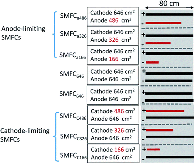 | ||
| Fig. 1 Schematic of the SMFCs with different electrode surface areas and SARa/c. “+”indicates cathode; “−”indicates anode; red bars indicate limiting electrodes. | ||
2.2 Operations of SMFCs
All SMFCs were firstly operated in single model until they reached stable power generation stages. After that, all anode- or cathode-limiting SMFCs were connected in series to the SMFC646. To test the possible effects of the hydraulic environment (separated or connected) on the performance of SMFC stacks, the water level in the container was increased to 1 cm higher than the separators between SMFCs so that the hydraulic environment could be switched from “separated” to “connected”.2.3 Polarization and power density analyzes
The polarization and power density curves of SMFCs or SMFC stacks were analysed at their stable status by changing the external resistor from 10![[thin space (1/6-em)]](https://www.rsc.org/images/entities/char_2009.gif) 000 to 50 Ohm or to a resistance causing voltage reversal in SMFC stacks. Ag/AgCl reference electrodes (0.197 V vs. standard hydrogen electrode, SHE) were used to record the potential variation of each electrode during polarization. The potential values were recoded after a 5 min-stable period for each resistance. Maximum power (MP) and internal resistance of the SMFCs were calculated as reported before.14
000 to 50 Ohm or to a resistance causing voltage reversal in SMFC stacks. Ag/AgCl reference electrodes (0.197 V vs. standard hydrogen electrode, SHE) were used to record the potential variation of each electrode during polarization. The potential values were recoded after a 5 min-stable period for each resistance. Maximum power (MP) and internal resistance of the SMFCs were calculated as reported before.14
3. Results and discussion
3.1 Effects of SARa/c on the power generation of single SMFCs
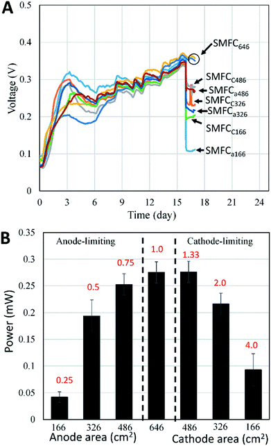
To evaluate the effects of electrode surface area, other possible differences such as microbial communities, substrate compositions and concentrations among different SMFCs must be avoid. Therefore, all SMFCs were initiated with the same electrode material and surface areas under the same operation condition. After a 15 days operation, all SMFCs showed similar power generation capabilities (0.35 ± 0.01 V) (Fig. 2A). The voltages of the SMFCs differed largely upon the cut of the electrodes. As expected, SMFC voltages deceased with the electrode surface area. According to polarization curve of each SMFC, the MP of SMFCs showed consistent trend (Fig. 2B) with their voltage curves (Fig. 2A). SMFC646 generated an MP of 0.28 mW and a maximum power density of 4.3 mW m−2 (normalized to cathode surface area), which was comparable to several SMFCs that operated in lab or in practical fields.15–18 The MP of the anode-limiting SMFCs increased from 0.04 to 0.25 mW when the anode increased from 166 to 486 cm2 (Fig. 2B). For the cathode-limiting SMFCs, the MP increased from 0.083 to 0.28 mW when the cathode increased from 166 to 486 cm2. By comparing the MP of SMFCc486 and SMFC646, an increase of cathode surface area from 486 to 646 cm2 did not increase MP, suggesting an optimal SARa/c of 1.33 for a single SMFC, i.e. the surface area of anode should be larger than that of the cathode. Fig. 2 also showed that the cathode-limiting SMFC always generated higher power than the anode-limiting SMFCs with the same electrode surface area, e.g. the MP of SMFCc166 was 0.09 mW while that of SMFCa166 was 0.05 mW, which also suggested higher electron transfer capability of cathode than the anode. All SMFCs showed no significant difference in MP when we switch the separated-hydraulic environment to shared-hydraulic environment.Our results supported the suggestion that the anode electron transfer rate was lower than that of cathode in SMFCs.6 However, the surface area difference between anode and cathode could be smaller than general consideration. Electrode generally accounts for the main capital cost of SMFCs as membrane separator was not needed in SMFCs.19 Although the optimal SARa/c may vary according to the electrode materials and environments, optimization of the electrode surface area is always needed to increase the cost-effectiveness of SMFCs, especially for the scale-up and field-application of SMFCs.
3.2 Effects of anode surface area on the power outputs of serial SMFC stacks
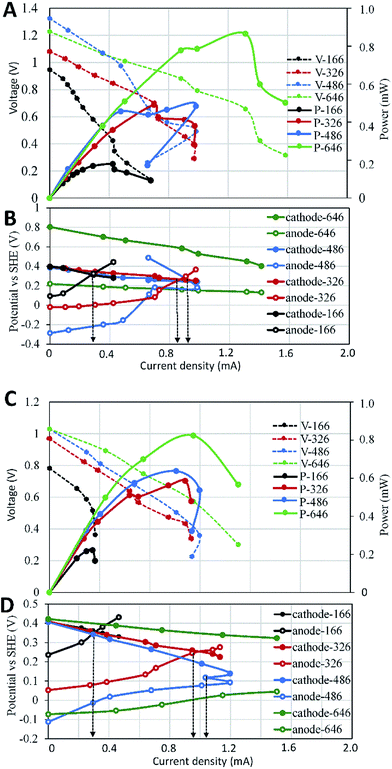
To analyse the effect of anode surface area on the serial stacks of SMFCs, we stacked SMFC646 with the anode-limiting SMFCs in which the surface areas of the limiting anode increased from 166 to 486 cm2. Under separated-hydraulic condition, the MP of those anode-limiting SMFCs stacks increased from 0.2 to 0.47 mW when the anode surface area increased from 166 to 486 cm2 (Fig. 3A), indicating that anodes were still the key limit in the power generation of those SMFC stacks. The MP of all the anode-limiting stacks were lower than the sum of the MP of the SMFCs before stack. For example, the MP of SMFC646–SMFCa166 stack was expected to be 0.32 mW as the according to the MP of the two SMFCs before stack (0.04 and 0.28 mW). However, the MP of SMFC646–SMFCa166 stack was 0.2 mW, i.e. 37.5% of the power lost after stack. Voltage reversal was observed in all anode-limiting stacks which could explain the power loss (Fig. 3B). In contrast, SMFC646–SMFC646 showed no voltage reversal and thus no power loss after stack. Electrode polarization showed more rapid potential increase of the limiting anodes relative to the cathode potentials, suggesting that anodes with smaller surface areas were the main reason for the voltage reversal in those SMFC stacks. Since all SMFCs were operated under the same condition, differences in the electrode surface area was supposed to be the only reason of the reversal. To rule out the possibility that lacking in electron donor caused reversal, we injected thiosulfate and acetate, two common electron donors in sediments, into the sediments which did not affect or even improved the voltage reversal. Polarization curves showed that compared to SMFC646–SMFC646, cell potentials fell more rapidly in the anode-limiting stacks, especially in the high-current area (Fig. 3A), suggesting higher potential loss in anode-limiting stacks caused by higher activation resistance, ohmic resistance and especially diffusion resistance.18 Fig. 3B further showed that the diffusion limitation mainly occurred on the limiting anodes, which was consistence with the low chemical diffusion rate in sediments. The reversal current increased from 0.33 to 0.85, 0.97 mA when the surface area of the limiting anode increased from 166 to 326, 486 cm2, respectively. The results suggested that the performance of a SMFC stack was determined by the limiting-electrode, and improved limiting-electrode performance could postpone or eliminate the voltage reversal.In addition to voltage reversal, ion-conduction is another possible reason that may cause voltage or power loss of MFCs in connected-hydraulic environments. When we switched the separated-hydraulic environment to shared-environment, the open circuit potential (OCP) of each stack decreased by 0.1–0.2 V, indicating ion-conduction occurred between the stacked SMFC units. However, the MP and voltage reversal current showed no significant difference before and after switching to shared-environment (Fig. 3C and D). Previous reports showed consistent results that ion-conduction could cause OCP loss in MFC stacks.12,20,21 However, inconsistent effects of ion-conduction on power generation were reported. In line with our result, Dekker et al. reported that shared-electrolyte had no effect on the power of serial MFC-stack.22 In contrast, Zhuang and Zhou reported that the ion-conduction could decrease power generation.20 In fact, many factors other than ion-conduction can affect the power generation of MFC stacks, e.g. internal resistance, voltage reversal. Therefore, the occurrence of ion-conduction in serial SMFCs does not ensure a power loss when the other factors facilitate power generation, which may explain the inconsistent effects of ion-conduction on power generation reported in different literatures.
3.3 Effects of cathode surface area on the power outputs of serial SMFC stacks
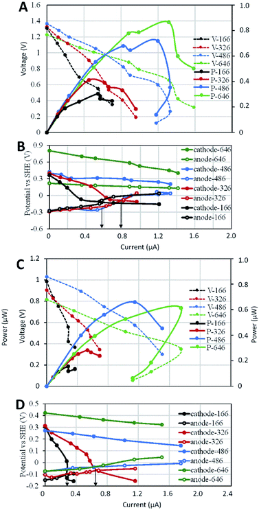
Similar to the anode-limiting stacks, the MP of cathode-limiting stacks increased with the cathode surface area (Fig. 4A), indicating cathode as the limiting factor in those stacks. Under separated-hydraulic condition, each cathode-limiting stack showed higher MP than that of the anode-limiting stack with the same electrode surface area, which was consistent with the higher MP of cathode-limiting SMFCs before stack. Voltage reversals were observed in the stacks of SMFC646–SMFCc166 and SMFC646–SMFCc326, but not in SMFC646–SMFCc486 and SMFC646–SMFCc646 (Fig. 4B), indicating the optimal SARa/c of single SMFCs could also postpone voltage reversal when they were serially stacked. Electrode polarization curves showed that the rapid cathode potential decease was the main reason for the reversal and the reversal current of SMFC646–SMFCc166 was smaller (0.57 mA) than that of SMFC646–SMFCc326 (0.8 mA). Both anode- and cathode-limiting stacks showed consistent trend that the limiting electrode was always the bottle neck in SMFC stacks and the worse the limiting electrode performed, the earlier the reversal occurred (i.e. the reversal current decreased with the surface area of the limiting electrode). In contrast to the anodic diffusion-dominated potential loss in anode-limiting stacks, cathodic ohmic resistance play a more important role in the potential loss of cathode-limiting stacks (Fig. 4B and D).When we switched separated cathode environments to shared environment, the OCP decreased by 0.3–0.4 V, indicated more OCP loss caused by ion-conduction in those cathode-limiting stacks relative to anode-limiting stacks (0.1–0.2 V). The MP of all cathode-limiting stacks showed significant decrease (Fig. 4C), different to the minor MP loss for in anode-limiting stacks (Fig. 3C). The cathode potential curves decreased while anode potential curves increased after switch to shared environment (Fig. 4D), indicating potential loss on both anode and cathode. Moreover, cathode potentials of SMFCc166 and SMFCc326 showed more rapidly decreased with current increase and showed voltage reversal at 0.29 and 0.65 mA respectively, which were lower than those (0.6 and 0.79 mA) under separated environments. SMFCs will be deployed in hydraulic-connected environments in practical application. Power loss caused by ion-conduction must be considered if multiple SMFCs are deployed. Enlarging the distance between SMFC units has been suggested to decrease the ion-conduction.20,21 However, the internal resistance and wire length of a SMFC stack may also increase with the distance.
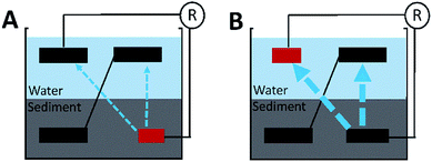
It is still unclear why the shared-environment decreased the power MP and reversal current of the cathode-limiting stacks but not of the anode-limiting stacks. One possible explanation is that (Fig. 5): in cathode-limiting stacks, the electron and proton generations on anodes were more rapid than the consumption by cathode due to the insufficient cathode surface area, resulting excess electrons and protons that contribute to parasitic cells.20,21 In anode-limiting stacks, the electron and proton generation of the anode was slower than the consumption by cathode, and thus less electron and proton can be used in forming parasitic cells. As a result, the cathode-limiting stacks can generate more power than the anode-limiting stacks with the same electrode surface area under separated environments because of higher reaction rate on cathode than anode. On the other hand, cathode-limiting stacks lost more power due to higher parasitic current loss under shared-hydraulic environments.
4. Conclusions
Optimization of electrode surface area is essential in scale-up and application of SMFCs. Our results suggested an optimal SARa/c between 1 to 1.33 for both single and serial-stacked SMFCs, which indicated a small difference in the reaction rates between SMFC anodes and cathodes. Voltage reversal occurred in serial SMFC stacks with unoptimal SARa/c but not in the optimized stacks, and the more the SARa/c deviated from the optimal value, the more easily the voltage reversal occurred. Compared to a separated-hydraulic environment, a connected-hydraulic environment showed no effect on the power generation of anode-limiting SMFC stacks but decreased the power generation and reversal current of cathode-limiting SMFCs.Conflicts of interest
There are no conflicts to declare.Acknowledgements
This research was supported by the National Natural Science Foundation of China (31570111, 51678163, U1701243), Pearl River S&T Nova Program of Guangzhou (201610010090), Science and Technology Project of Guangzhou (201707020021), Guangdong Provincial Science and Technology Project (2016B070701017), Guangdong Provincial Natural Science Foundation (2014A030308019, 2016A030306021), Guangdong Ocean and Fishery Administration Project (A201601D01), Open Project of Key Laboratory of Environmental Biotechnology (CAS kf2016003), and GDAS Special Project of Science and Technology Development (2017GDASCX-0403, 2017GDASCX-0401).References
- L. M. Tender, C. E. Reimers, H. A. Stecher, D. E. Holmes, D. R. Bond, D. A. Lowy, K. Pilobello, S. J. Fertig and D. R. Lovley, Nat. Biotechnol., 2002, 20, 821–825 CrossRef PubMed.
- C. Donovan, A. Dewan, D. Heo and H. Beyenal, Environ. Sci. Technol., 2008, 42, 8591–8596 CrossRef PubMed.
- L. Hsu, B. Chadwick, J. Kagan, R. Thacher, A. Wotawa-Bergen and K. Richter, RSC Adv., 2013, 3, 15947–15954 RSC.
- X. Xu, Q. L. Zhao and M. S. Wu, RSC Adv., 2015, 5, 62534–62538 RSC.
- B. E. Logan, M. J. Wallack, K. Y. Kim, W. H. He, Y. J. Feng and P. E. Saikaly, Environ. Sci. Technol. Lett., 2015, 2, 206–214 CrossRef.
- W. W. Li and H. Q. Yu, Biotechnol. Adv., 2015, 33, 1–12 CrossRef PubMed.
- Y. Yang, Z. Lu, X. Lin, C. Xia, G. Sun, Y. Lian and M. Xu, Bioresour. Technol., 2015, 179, 615–618 CrossRef PubMed.
- U. Karra, G. X. Huang, R. Umaz, C. Tenaglier, L. Wang and B. K. Li, Bioresour. Technol., 2013, 144, 477–484 CrossRef PubMed.
- F. Zhang, L. Tian and Z. He, J. Power Sources, 2011, 196, 9568–9573 CrossRef.
- B. E. Logan, Appl. Microbiol. Biotechnol., 2010, 85, 1665–1671 CrossRef PubMed.
- T. Ewing, P. T. Ha, J. T. Babauta, N. T. Tang, D. Heo and H. Beyenal, J. Power Sources, 2014, 272, 311–319 CrossRef.
- M. A. G. Azari, R. Gheshlaghi, M. A. Mahdavi and E. Abazarian, Int. J. Hydrogen Energy, 2017, 42, 5252–5260 CrossRef.
- J. Li, H. J. Li, Q. Fu, Q. Liao, X. Zhu, H. Kobayashi and D. D. Ye, Int. J. Hydrogen Energy, 2017, 42, 27649–27656 CrossRef.
- B. E. Logan, B. Hamelers, R. A. Rozendal, U. Schrorder, J. Keller, S. Freguia, P. Aelterman, W. Verstraete and K. Rabaey, Environ. Sci. Technol., 2006, 40, 5181–5192 CrossRef PubMed.
- S. W. Hong, H. J. Kim, Y. S. Choi and T. H. Chung, Bull. Korean Chem. Soc., 2008, 29, 2189–2194 CrossRef.
- C. E. Reimers, L. M. Tender, S. Fertig and W. Wang, Environ. Sci. Technol., 2001, 21, 192–195 CrossRef.
- C. Xia, M. Xu, J. Liu, J. Guo and Y. Yang, Bioresour. Technol., 2015, 190, 420–423 CrossRef PubMed.
- C. T. Wang, Y. C. Lee, Y. T. Ou, Y. C. Yang, W. T. Chong, T. Sangeetha and W. M. Yan, Appl. Energy, 2017, 204, 620–625 CrossRef.
- Y. F. Zhang and I. Angelidaki, Environ. Sci. Technol., 2016, 50, 5432–5433 CrossRef PubMed.
- L. Zhuang and S. G. Zhou, Electrochem. Commun., 2009, 11, 937–940 CrossRef.
- D. Kim, J. An, B. Kim, J. K. Jang, B. H. Kim and I. S. Chang, ChemSusChem, 2012, 5, 1086–1091 CrossRef PubMed.
- A. Dekker, A. Ter Heijne, M. Saakes, H. V. M. Hamelers and C. J. N. Buisman, Environ. Sci. Technol., 2009, 43, 9038–9042 CrossRef PubMed.
| This journal is © The Royal Society of Chemistry 2018 |

