
 Open Access Article
 This Open Access Article is licensed under a Creative Commons Attribution-Non Commercial 3.0 Unported Licence
Flexible PANI/SWCNT thermoelectric films with ultrahigh electrical conductivity†
Ruili Wua,
Haocheng Yuan a,
Chan Liub,
Jin-Le Lan*a,
Xiaoping Yang*a and
Yuan-Hua Linb
a,
Chan Liub,
Jin-Le Lan*a,
Xiaoping Yang*a and
Yuan-Hua Linb
aState Key Laboratory of Organic–Inorganic Composites, Beijing University of Chemical Technology, Beijing 100029, China. E-mail: lanjl@mail.buct.edu.cn; yangxp@mail.buct.edu.cn
bState Key Laboratory of New Ceramics and Fine Processing, School of Materials Science and Engineering, Tsinghua University, Beijing, 100084, P. R. China
First published on 19th July 2018
Abstract
The effects of polyaniline (PANI) with different polymerization times on the film-forming and thermoelectric properties as well as on the performance of SWCNTs/PANI composites were systematically investigated in this study. It was found that the film-forming and flexibility of PANI films improved with the increase in polymerization time. We showed that a super high conductivity of ∼4000 S cm−1 can be achieved for the SWCNTs/PANI composite film, which is the highest value for the SWCNTs/PANI system at present. Both the electrical conductivity and power factor increase by an order of magnitude than that of pure PANI films and far exceed the theoretical value of the mixture model. These results suggest that the sufficiently continuous and ordered regions on the interlayer between the filler and matrix are key to improve the electrical conductivity of composites. Finally, the maximum PF reaches 100 μW m−1 K−2 at 410 K for the 0.6CNT/PANI5h. Furthermore, it is found that the composite films have excellent environmental and structural stability. Our results can deepen the understanding of organic–inorganic thermoelectric composite systems and facilitate the practical application of flexible and wearable thermoelectric materials.
1. Introduction
Increasing attention has been drawn towards the organic materials for application as the thermoelectric materials owing to their light weight, facile processability, and environmentally benign features.1–3 These materials can be used for flexible power-conversion devices in this era of intelligent electronic outbreak. In particular, the inherent low thermal conductivity of organic materials makes them the most promising as candidates for thermoelectric materials as determined by the dimensionless figure of merit: ZT = S2σT/κ (S, σ, T, and κ are the Seebeck coefficient, electrical conductivity, absolute temperature, and thermal conductivity, respectively).4,5 For the organic thermoelectric materials, the power factor (PF, defined as S2σ) becomes a pre-evaluation parameter of thermoelectric performance because their thermal conductivity is always maintained at a low level (∼0.3–0.5 μW m−1 K−1).6,7In recent years, the prevailing method for enhancing the thermoelectric properties of organic materials is to prepare the inorganic–organic composites. The typical organic materials are conducting polymers. Among them, polyaniline (PANI)8–13 and poly(3,4-ethylenedioxythiophene) (PEDOT)14–17 have recently drawn much attention due to the facile synthesis of polyaniline and the high conductivity of PEDOT:PSS post treatment. The wearable flexible devices should have good environmental stability. Thus, PANI can be a better candidate compared with PEDOT:PSS as PEDOT:PSS becomes unstable due to water absorption from the air,18 while PANI is insoluble in water and most of solvents. Furthermore, the low Seebeck coefficient of pure polymer limits its application in practice. The inorganic fillers with high conductivity and/or high Seebeck coefficient have been usually incorporated into a conducting polymer matrix to enhance the TE properties of the composites, such as carbon nanotubes,19,20 graphene,21,22 transition metal chalcogenides (SnSe, TiS2),23,24 nanometals and alloys (Te, Bi2Te3).25,26 Previous studies have shown that carbon nanotubes can enhance thermoelectric properties27,28 and direct mixing is a simple and effect method.29
Previous studies have generally confirmed that the increase in the TE properties of composites could be attributed to interactions between polymers and fillers. One is the π–π conjugation, particularly between polymer and one-dimension fillers. Several groups have reported that SWCNT/PANI composites exhibited significantly higher electrical conductivity than that of polymer matrices, as these composites do not obey the general series- and parallel-connected mixture law, and hence exceed the predicted value of the law. This phenomenon is most evident between one-dimensional fillers and polymers, such as CNT/PANI30,31 and Te/PANI.32,33 It is usually conjectured that the strong π–π conjugations between inorganic and polyaniline molecules would induce the formation of an ordered chain structure and therefore, significantly enhance the electric conductivity.
Another is the interface interactions between filler and polymers that lead to the formation of an interface layer, which on connecting the polymer and the inorganic material, is thought to have an energy filtering effect by allowing high-energy carriers to pass and filtering out low-energy carriers. The carrier energy-filtering can increase the carrier mobility, thus significantly improving S and exceeding the mixture law. This effect is more evident in the composites of one-dimensional or two-dimensional nanomaterials and polymers, such as PEDOT/SnSe.23,34 In these systems, the values of Seebeck coefficient exceed the series-connected and parallel-connected models, and are traceable to the existence of the interface, or else these values would be in agreement with the series- and parallel-connected model if the interfaces can be neglected.
In other systems, there are some cases where σ and S both exceed the theoretical model values, such as graphene/PANI system studied by Q. Yao et al.22 In other words, the improvements achieved so far are based on some possible mechanisms and a systematic study is still lacking.
At present, the academic community has extensively explored the PANI system. Most of the research groups have mainly focused on the influence of different filler content on the properties of the composites system. The effects of solvents on the structure and performances of polyaniline were also studied, in which the molecular chain conformation of PANI changed from a compact coil to an expanded coil by dissolving it in m-cresol.10,35 However, only few studies have been conducted to investigate the influence of PANI matrix on the film-forming property and thermoelectric properties of CNT/PANI composite materials.
Herein, we carefully designed and investigated the SWCNTs/PANI system from a new perspective: (i) the effect of polymerization time on the film-forming, flexibility and thermoelectric properties of pure PANI and its composite; (ii) the effect of SWCNT on the composite system and the examination of the possible mechanisms, e.g., mixture law and energy filtering assumption; and (iii) checking the bendable and longtime stability of PANI composite film for the potential wearable application. Interestingly, a composite film with super high conductivity of ∼4000 S cm−1 was obtained, which was the highest performance value of the reported SWCNTs/PANI system. Moreover, the composites films have excellent environmental stability (more than half a year) and structural stability (bending more than 100 times).
2. Experimental section
2.1 Materials
All chemicals used in this study were of analytical grade. Aniline (ANI) was purchased from Tianjin Guangfu Chemical Reagent Factory. Ammonium persulfate (APS) and camphorsulfonic acid (CSA) were purchased from Beijing BAILINGWEI Technology Co., Ltd. m-Cresol was received from Shanghai Aladdin Biochemical Technology Co. Ltd. Ammonia solution (28–30%) and hydrochloric acid (HCl, 35–38%) were obtained from Sigma-Aldrich. All chemicals were used as received. Highly purified large surface area SWCNTs (diameter: 1–2 nm; length: 5–30 μm; purity: >95.0 wt%; specific surface area: >1075 m2 g−1) were provided by Nanjing XFNANO Materials Technology Co. Ltd.2.2 Preparation of PANI and SWCNTs/PANI free-standing films
![[thin space (1/6-em)]](https://www.rsc.org/images/entities/char_2009.gif) :1. The product was filtered and then, the collected PANI powder was added in 1 M ammonia solution with continuous stirring for 24 h at room temperature. Subsequently, the PANI-ammonia solution was filtered and washed using deionized water and ethanol several times, followed by vacuum drying at 55 °C.:56) was added into the m-cresol solution with constant stirring for at least 8 hours, forming a black-green colored solution. The obtained CSA-redoped PANI achieved better electrical conductivity than pure PANI. Then, the mixed solution was coated on 30 × 15 mm2 glass substrates and dried at 55 °C in a vacuum oven. The glass substrates were cleaned previously by sequential sonication in acetone, deionized water and ethanol each for fifteen minutes.
:1. The product was filtered and then, the collected PANI powder was added in 1 M ammonia solution with continuous stirring for 24 h at room temperature. Subsequently, the PANI-ammonia solution was filtered and washed using deionized water and ethanol several times, followed by vacuum drying at 55 °C.:56) was added into the m-cresol solution with constant stirring for at least 8 hours, forming a black-green colored solution. The obtained CSA-redoped PANI achieved better electrical conductivity than pure PANI. Then, the mixed solution was coated on 30 × 15 mm2 glass substrates and dried at 55 °C in a vacuum oven. The glass substrates were cleaned previously by sequential sonication in acetone, deionized water and ethanol each for fifteen minutes.For preparing SWCNTs/PANI films, CNTs with different weight fractions (0, 5, 10, 30, 50, 60, 70, and 90 wt%) were added into the m-cresol solution simultaneously and the mixed solution was stirred for one day. The obtained suspension was cast on glass substrates and dried at the same conditions as pure PANI films. These films were referred to as PANI5/CNT, PANI6/CNT, PANI12/CNT, PANI18/CNT, and PANI24/CNT. All dry films can be easily peeled off from the substrate by immersing the films in deionized water due to the hydrophobicity of PANI.
2.3 Characterization
We performed gel permeation chromatography (GPC) (DMF phase) to obtain the molecular weights of PANI. The morphology of PANI and SWCNTs/PANI films was investigated using a field emission scanning electron microscope (FE-SEM, Supra55, Carl Zeiss, Germany) and a transmission electron microscope (TEM, 2000 EX, JEOL, Japan) at an accelerating voltage of 100 kV. Raman spectra were recorded on an inVia Reflex confocal Raman microscope (Renishaw, UK) within the wavenumber range of 1000–2000 cm−1 with argon ion laser at the excitation wavelength of 633 nm. The phases of PANI and SWCNTs/PANIs were characterized via X-ray diffraction (XRD) using a Bruker D8 Advance X-ray diffractometer with Cu Kα radiation in the 2θ range of 5–90°.Since the SWCNTs/PANI composite films are rectangular in shape, we can directly perform the electrical conductivity and Seebeck coefficient tests for these films using the room temperature thin-film thermoelectric parameter test system (MRS-3, Wuhan Joule Yacht China Co., Ltd). The temperature dependent thermoelectric performances were measured from 300 K to 410 K under helium atmosphere using a ZEM-3 system (ULVAC-RIKO, Japan). The thicknesses of the films were measured using a step profiler. The width of the films was measured by a slide caliper rule. The carrier concentration and carrier mobility were investigated by a Hall measurement system (Cryogenic Limited, U.K.) with a 5 T magnetic field at room temperature.
3. Results and discussion
All the film samples were prepared by casting the mixed solution into 30 × 15 mm2 glass substrates. The schematic of the formation process of PANI films and SWCNTs/PANI flexible composite films is shown in Fig. 1. All of the as-prepared films were smoothly coated on the glass substrates and the freestanding and flexibility film could be easily peeled off from glass substrates (Fig. S1†). The film obtained at 5 h polymerization time would break when peeled off, while other films obtained at 6–18 h polymerization time would break after folding and bending. Only the film obtained at 24 h polymerization time shows outstanding flexibility even on folding and blending, which is superior to those of conventional inorganic thermoelectric materials and makes it possible for the film to be applied in bendable or curved energy converters. This result indicates that the increase in PANI polymerization time can improve the film-forming properties of PANI and enhance the flexibility of the film.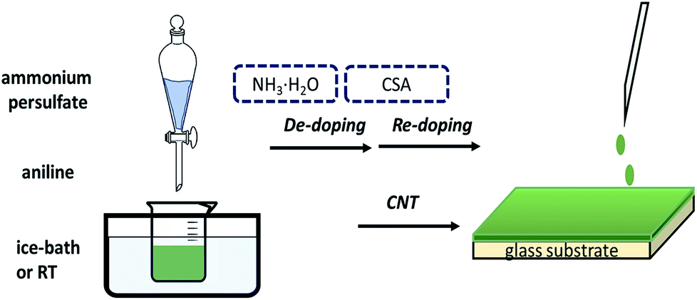 | ||
| Fig. 1 Illustration of the preparation procedure of flexible PANI films. | ||
Fig. 2 shows some typical surface and cross-section SEM images of pure PANI films. The as-prepared pure PANI films were dense and smooth. The surface of PANI films is uniform. However, the cross-section morphologies of films with different polymerization times were different. The PANI films comprised deposited “particles” when polymerization time of PANI was 5 and 6 hours, whereas when the polymerization time was more than 12 hours, the PANI films were composed of nanowires-like material. The film forming ability of PANI could vary because PANI with different polymerization times have different molecular weights, and exhibit different structure states during the film formation.
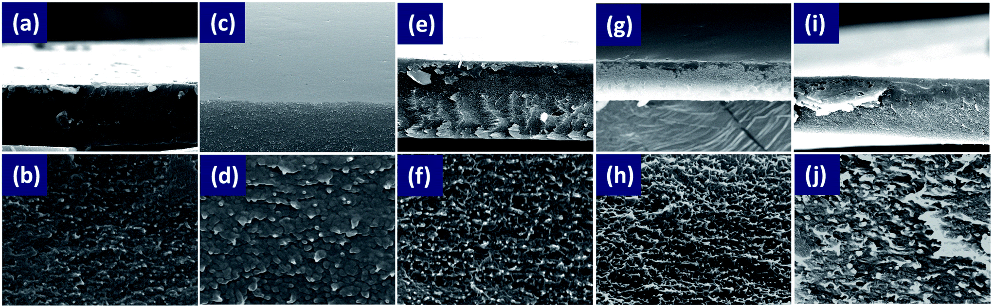 | ||
| Fig. 2 SEM images of cross-sections of pure PANI films with different polymerization times: 5 h (a and b), 6 h (c and d), 12 h (e and f), 18 h (g and h), and 24 h (i and j). | ||
Fig. 3(a) shows the GPC of PANI with different polymerization times. As shown in the figure, the effect of PANI polymerization time on PANI molecular weight is evident. The PANI molecular weight was almost monodispersed when polymerization time was 5 hours, and its polydispersity index (1.03) is shown in Table S1.† The polydispersity index increased as the polymerization time increased, and a higher molecular weight polymer was obtained. Thus, the film-forming property of PANI is closely connected with molecular weight and molecular weight distribution.
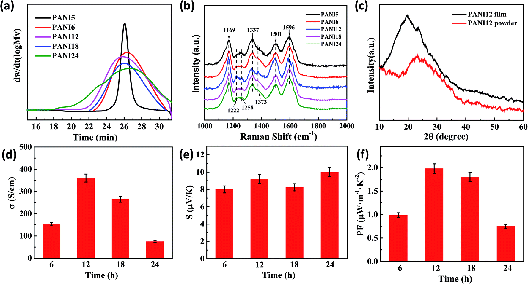 | ||
| Fig. 3 (a) GPC and (b) Raman spectra of PANI with different polymerization times. (c) XRD patterns of PANI12 film and power. (d) The electrical conductivity, (e) Seebeck coefficient, and (f) PF values of PANI with different polymerization times. | ||
Fig. 3(b) presents the Raman spectra of the pure PANI films with the different polymerization times. The C–H bending vibration of the quinoid/benzenoid ring (1171 cm−1), the C–N+ vibration of the quinoid ring (∼1337 cm−1), delocalized polaron vibration in the extended polymeric conformation (∼1373 cm−1 and 1635 cm−1), N–H stretching vibration (∼1501 cm−1), C–N stretching vibration (∼1258 cm−1) and C–C stretching vibration of the benzenoid ring (∼1596 cm−1) were observed in all the samples. It was found that the peak intensities at 1171 cm−1, 1501 cm−1 and 1596 cm−1 in the PANI films increased significantly for the films obtained in 12 hours polymerization time, indicating that the crystal of PANI12 film is larger than that of the other films. It was worth noting that the intensity of the delocalized polaron vibrations peaks in the extended polymeric conformation (1373 cm−1 and 1635 cm−1) increased significantly and the intensity of the peak at 1258 cm−1 decreased for the film obtained in 12 hours polymerization time, suggesting the formation of an extended coil of polyaniline in the film from the compact coil, for which the m-cresol played an important role.10–13 Furthermore, some peaks (1337 cm−1, 1501 cm−1, and 1596 cm−1) red shifted in the Raman spectra, indicating that there exists strong π–π conjugated interactions between PANI so as to reduce the intermolecular chain spacing. Since the distance between molecules determines the electric coupling between them, reducing the distance between the molecules would increase the mobility as well as the electrical conductivity.10
XRD characterization gave the evidence for change in the molecular chain structure by m-cresol solution treatment. Fig. 3(c) and S2† present the XRD patterns of pure PANI powder and PANI films (Fig. 3(c) presents the XRD pattern of PANI12 as an example). After m-cresol solution treatment, the intensity of the peak increased and the peak positions significantly shifted to a lower angle, suggesting that the conformation of polymer became more expanded from “compacted coil” and the crystallinity of PANI molecular chains increased.
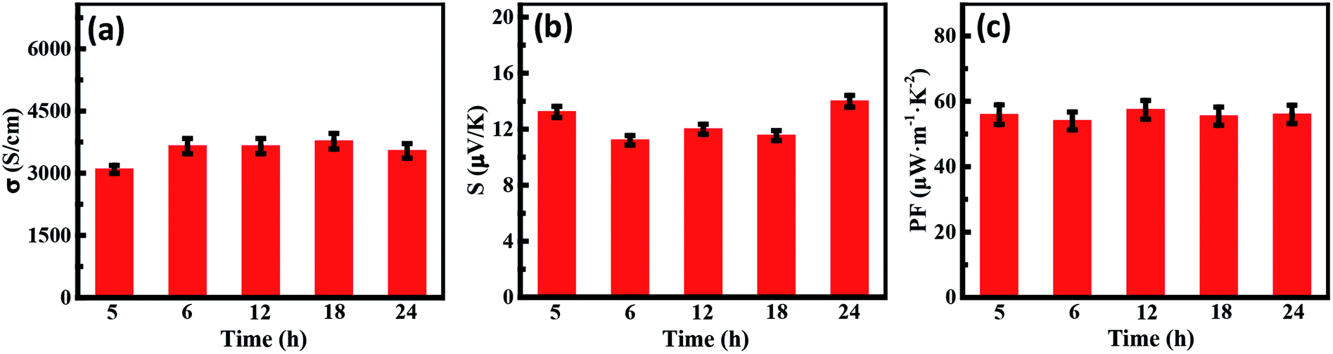
Fig. 3(d–f) show the TE properties of PANI films as a function of polymerization time. The highest electrical conductivity (360 ± 70 S cm−1) of pure PANI films is obtained for the sample with 12 h polymerization time. This value is higher than the previous highest value reported by Yao et al. (290 S cm−1).30 This is attributed to the following: (i) the PANI of higher molecular weight has better conductive network due to the changed PANI structural morphology; (ii) the molecular conformation of PANI changed from a compacted coil to an expanded coil through the chemical interactions between PANI and m-cresol.10 The Raman spectra and XRD patterns provide proof for the highest conductivity when the polymerization time is 12 h.
The different mass fraction of SWCNTs/PANI nanocomposites have been determined, as shown in Table S2.† In order to clearly investigate the effect of SWCNT content on the thermoelectric properties of composites, the almost monodispersed PANI matrix (polymerization time of 5 h) was chosen. The typical surface and cross-section SEM images of SWCNTs/PANI composite films with different SWCNT contents are displayed in Fig. 4 and S3.† Increasing amounts of SWCNTs were clearly observed on the surface in the composite film and were pulled out of PANI cross-sectionally with the increase in SWCNT content. The thickness of the composite films containing 10 wt%, 50 wt%, and 90 wt% SWCNT content are 1.3 μm, 3.6 μm and 6 μm, respectively. The quality of composite films gets worse quickly when the SWCNT content is increased to 90 wt%, which can significantly influence the thermoelectric properties of the films. From the TEM image (Fig. S4†) of the SWCNTs/PANI composite films, a thin PANI layer closely coated on the surface of the SWCNTs can be clearly observed. This observation further proves that the PANI chains are wrapped around the outside of the SWCNTs, which can be attributed to the interactions between PANI and SWCNTs.
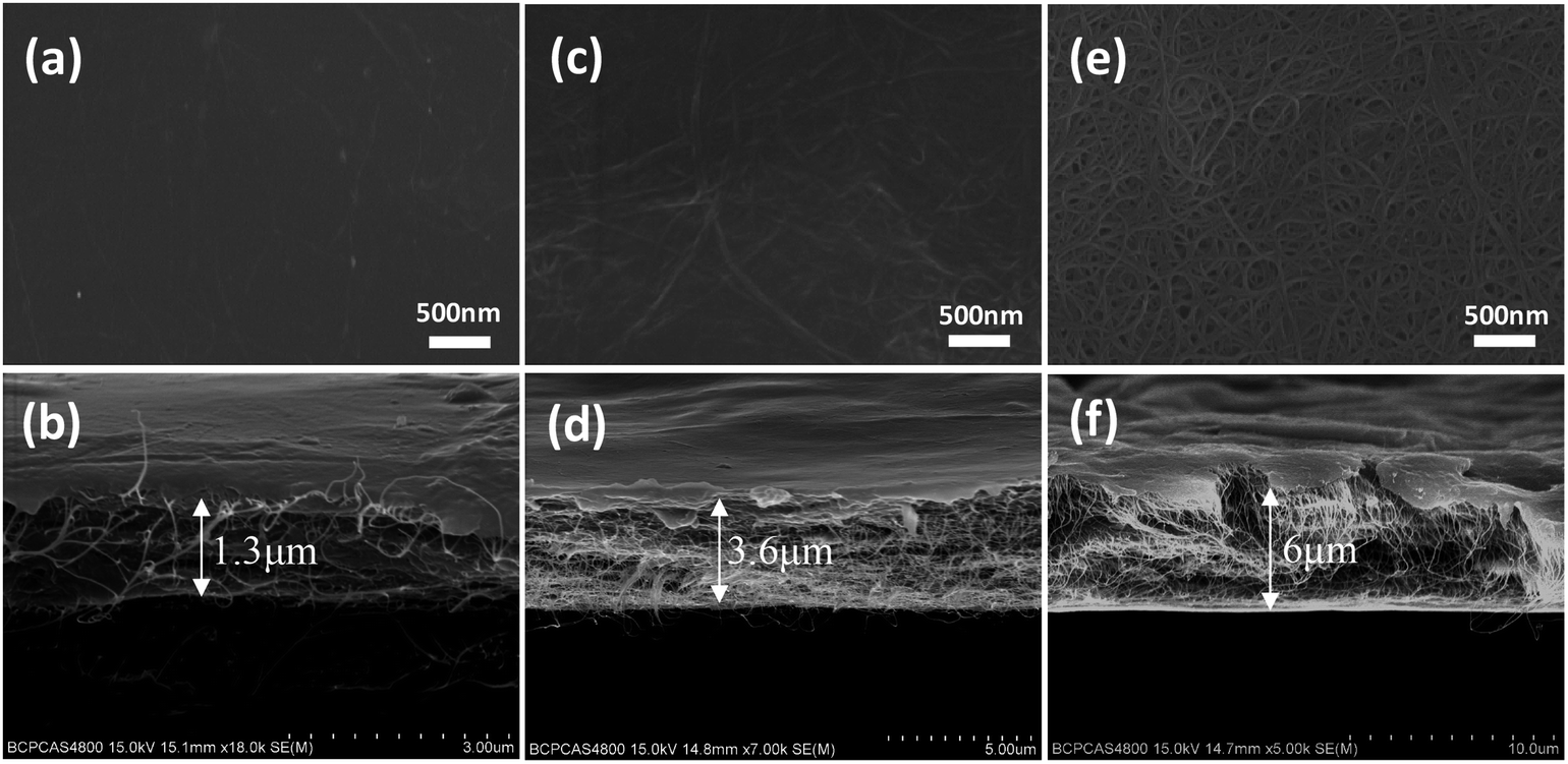 | ||
| Fig. 4 The typical SEM images of SWCNTs/PANI composite films' surface and cross-section, 10% SWCNT (a and b); 50% SWCNT (c and d); 90% SWCNT (e and f). | ||
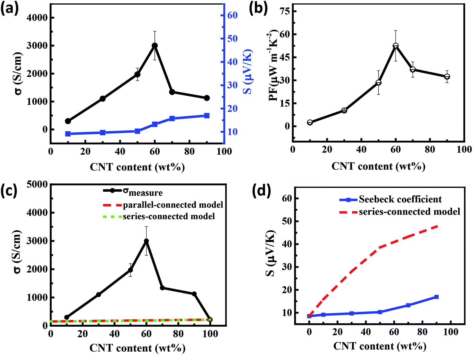
Fig. 5 presents the thermoelectric properties of the SWCNTs/PANI film as a function of the mass fraction of SWCNTs at room temperature. The electrical conductivity increased with the increase in SWCNT content, reaching the peak value for the sample with 60 wt% SWCNTs, while Seebeck coefficient of composites monotonously and slightly increased. When the content of SWCNTs is 90 wt%, the conductivity suddenly drops due to the high content of SWCNTs with uneven dispersion and poor quality of the film (Fig. 5(a)). Consequently, the highest power factor of the PANI/SWCNT film was about 56 μW m−1 K−2 at 60 wt% SWCNT (Fig. 5(b)).
 | ||
| Fig. 5 (a) The electrical conductivity, Seebeck coefficient, and (b) the PF values of SWCNTs/PANI composites with different SWCNT content. (c) Electrical conductivity and (d) Seebeck coefficient values of the SWCNTs/PANI composites with the series-connected model as a function of the SWCNT concentration. | ||
Generally, the theoretical property values of composites can be determined within series and parallel connected models originating from the derivation of the equations using the Ohm's law in the simple filler/matrix system if the interfaces are not considered.36,37 For the SWCNTs/PANI system, the volume fraction of SWCNTs and PANI can be substituted by the weight fraction due to the SWCNTs having density similar to that of PANI. The dashed line in Fig. 5(c) is the estimated electrical conductivity based on the two mixture models (for detailed calculations see the eqn (S2) and (S3) in ESI†). Interestingly, it is shown that the experimental conductivity values of the SWCNTs/PANI composite film are significantly higher than the calculated values. The percolation theory is a reasonable tool to describe the insulator-to-conductor transitions in composites. The Seebeck coefficient of the composites should increase linearly if the compound obeys the mixture rule, as shown in Fig. 5(d) (detailed calculation see the eqn (S4) in ESI†). In fact, the Seebeck coefficient only slightly increased in our experiment. The energy filtering effect mentioned in previous studies is not applicable in our study and cannot explain the change in Seebeck coefficient.
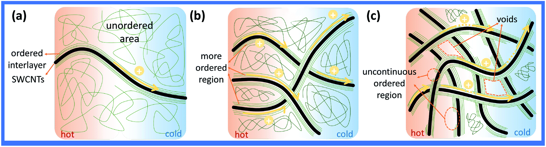
In general, the percolation threshold (critical concentration) is not more than 10 vol% (wt%) in the CNT-based systems due to their high aspect ratio. In fact, the content of CNT has exceeded the percolation threshold in most of the previous studies on thermoelectric composites. For the sample with less than 10 wt% SWCNT, some of the individual SWCNT or nanotube clusters in SWCNTs/PANI samples are substantially isolated by the polymer coating, thus preventing direct contact between the SWCNTs, so that the σ of the films increase slowly, as shown in Fig. 6(a). When the content of SWCNTs is more than 10 wt%, the electrical conductivity of the composite films increase sharply since the conductivity of the films is dominated by the three-dimensional interconnected network formed by SWCNTs, as shown in Fig. 6(b).
 | ||
| Fig. 6 The schematic of electron transport in composites film: (a) SWCNTs < 10 wt%, (b) SWCNTs > 10 wt%, and (c) SWCNTs > 90 wt%. | ||
However, our raw material SWCNTs have similar conductivity σ (217 S cm−1) compared with pure PANI films. Therefore, the conductivity of composites should not exceed the maximum value of SWCNTs and PANI based on the mixture law and percolation theory. There is no doubt that the percolation theory also cannot explain this phenomenon. In this case, the high conductive interlayer between PANI and SWCNTs may reasonably contribute to the high conductivity of composites.12,32 The Raman spectra of the SWCNTs/PANI system clearly showed strong π–π conjugated interactions between PANI and SWCNTs, and the conjugation could enhance the electron delocalization and cause a Raman shift, as shown in Fig. S5b.† The Hall measurement of the composite film was conducted and the results are shown in Table 1. It was found that the carrier concentration and mobility of composite was more than one order of magnitude higher than that of SWCNTs. The previous study indicates that the interface layer in composite can provide high carrier concentration and high mobility,25,30 which is the main reason for the abnormal high conductivity of our composite film. When the SWCNTs form the network, the interlayer region also connect together, making the delocalization carriers spread over the entire network and enabling the rapid propagation of electrons along the π–π conjugated ordered region, as shown in Fig. 6(b). However, when the SWCNT content is too high, the PANI is not sufficient to surround the entire SWCNTs network. Thus, the interlayer is incomplete, resulting in a hopping transport mechanism that severely affects the carrier transport and conductivity, as shown in Fig. 6(c).
| Samples | CNT | PANI/0.3CNT | PANI/0.5CNT | PANI/0.7CNT | PANI/0.9CNT |
|---|---|---|---|---|---|
| Carrier concentration (1022 cm−3) | 0.45 | 1.58 | 4.56 | 2.37 | 0.95 |
| Carrier mobility (cm2 V−1 s−1) | 0.02 | 0.40 | 0.29 | 0.49 | 0.23 |
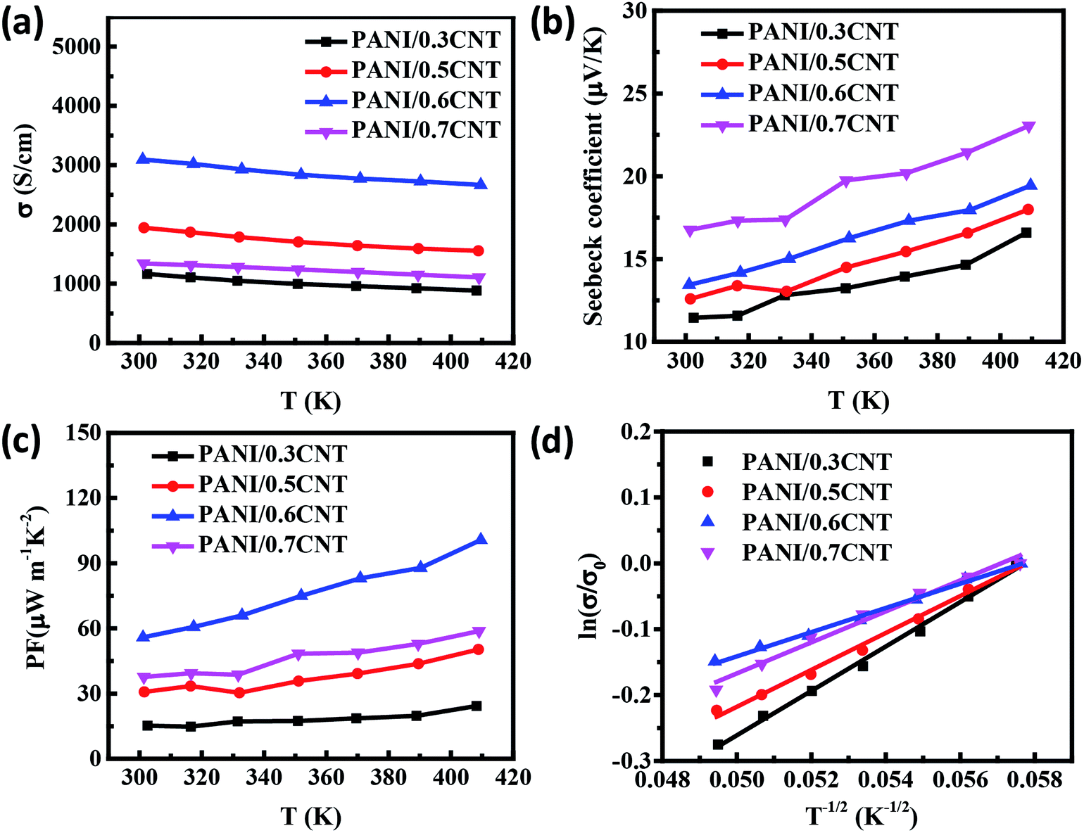
In order to study the transport properties of the composite film, we further analyzed the temperature dependent change in the TE properties of 30–70 wt% PANI5/CNT composite films in the range of 300–410 K, as shown in Fig. 7. The electrical conductivity decreases with the increase in temperature (Fig. 7(a)), indicating a typical metallic conducting behaviour of the film. The slope of the S–T curves increases with increase in temperature (Fig. 7(b)), demonstrating a typical metallic thermoelectric behavior,38 identical to the result proved by the σ–T curve. The increasing trend of Seebeck coefficient is much slower than the change in σ. PF is mainly determined by the conductivity and hence, the maximum PF reaches 100 μW m−1 K−2 at 410 K for the PANI/0.6CNT sample (Fig. 7(c)). In addition, the relation between electrical conductivity and temperature can fit with the Variable-Range Hopping model: 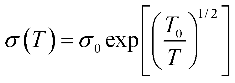 ,39,40 where σ0 is a constant and T0 is a characteristic temperature associated with energy barrier constant of the CNT-to-CNT jump and reflects the local state energy barrier of the materials. The fitting data of the conductivity of the SWCNTs/PANI composites with different SWCNTs content as a function of temperature is reflected in Fig. 7(d). It can be found that the slope of the ln(σ/σ0) vs. T−1/2 line, reflecting the value of T0 (the T0 of 0.3, 0.5, 0.6, 0.7CNT composites is 33.7 K, 28 K, 18.4 K, 23.5 K, respectively), first decreased and then increased with the increase in SWCNT content, indicating that the addition of SWCNTs reduced the localized energy barrier of the film during electron transport below 60 wt%. This is because the complete conductive path and a tight three-dimensional connected network leads to the generation of high carrier concentration, resulting in electrical properties with metallic property. In addition, the more complete structural pathway will reduce the energy barrier and thus, better electrical conductivity can be obtained. The PANI/0.6CNT with 60 wt% SWCNTs has the smallest energy barrier and is consistent with the highest room temperature conductivity due to the appropriate interlayer conduction paths as discussed above. Thus, the highest PF 100 μW m−1 K−2 is obtained for the PANI/0.6CNT sample at 410 K.
 | ||
| Fig. 7 Temperature dependence of (a) electrical conductivity, (b) Seebeck coefficient, and (c) power factor of SWCNTs/PANI films. (d) Analyses of the temperature dependences of the electrical conductivity with the 1D VRH model for SWCNTs/PANI films. | ||
In order to further improve the properties of the composites, PANI at various polymerization times were composited with fixed SWCNT of 60 wt% content. The characterization of composites is shown in Fig. S5.† Compared to pure PANI and SWCNTs, some characteristic diffraction peaks of PANI after compositing almost disappeared in the XRD patterns and Raman spectra of the composites, which indicated that the arrangement of PANI molecular chains changed from the curled state to the stretched state and strong π–π conjugated interactions exist between the PANI and SWCNTs. As shown in Fig. 8, the polymerization time of PANI has a weak effect on the thermoelectric properties of composites. This is because the complete three-dimensional interconnected network is formed in the SWCNT content of 60 wt%. More importantly, the highly conductive interlayer path is also complete due to the alignment of the PANI molecular chains on the surface of the SWCNTs, which primary influence the conductivity. Furthermore, the XRD patterns and Raman spectra of the composites are basically the same in SWCNTs/PANI composites with the PANI of different polymerization times, indicating that PANI with different polymerization time does not have a very significant effect on the structure of the composites compared to that of the high content filler. Finally, the high power factor ∼60 μW m−1 K−2 is achieved in all the samples and the electrical conductivity of ∼4000 S cm−1 is obtained in PANI12/CNT, PANI18/CNT, and PANI24/CNT, which is the highest value among the reported SWCNTs/PANI composite systems.41 This study provides us a better understanding of the impact of polymer and filler on the composite thermoelectric properties.
 | ||
| Fig. 8 (a) The electrical conductivity, (b) Seebeck coefficient, and (c) PF values of SWCNT/PANI composites with different polymerization times. | ||
In order to investigate the stability of the composites, we determined the electrical conductivity and Seebeck coefficient of the samples with different SWCNTs content after repeated bending 100 times by hand operation, as shown in Fig. 9(a–c). Futhermore, the properties of the composites after a half year were tested. It was found that their TE properties almost remain unchanged after bending as well as after 0.5 year (Fig. 9(d)), indicating that the composite films have both mechanical and environmental stability.
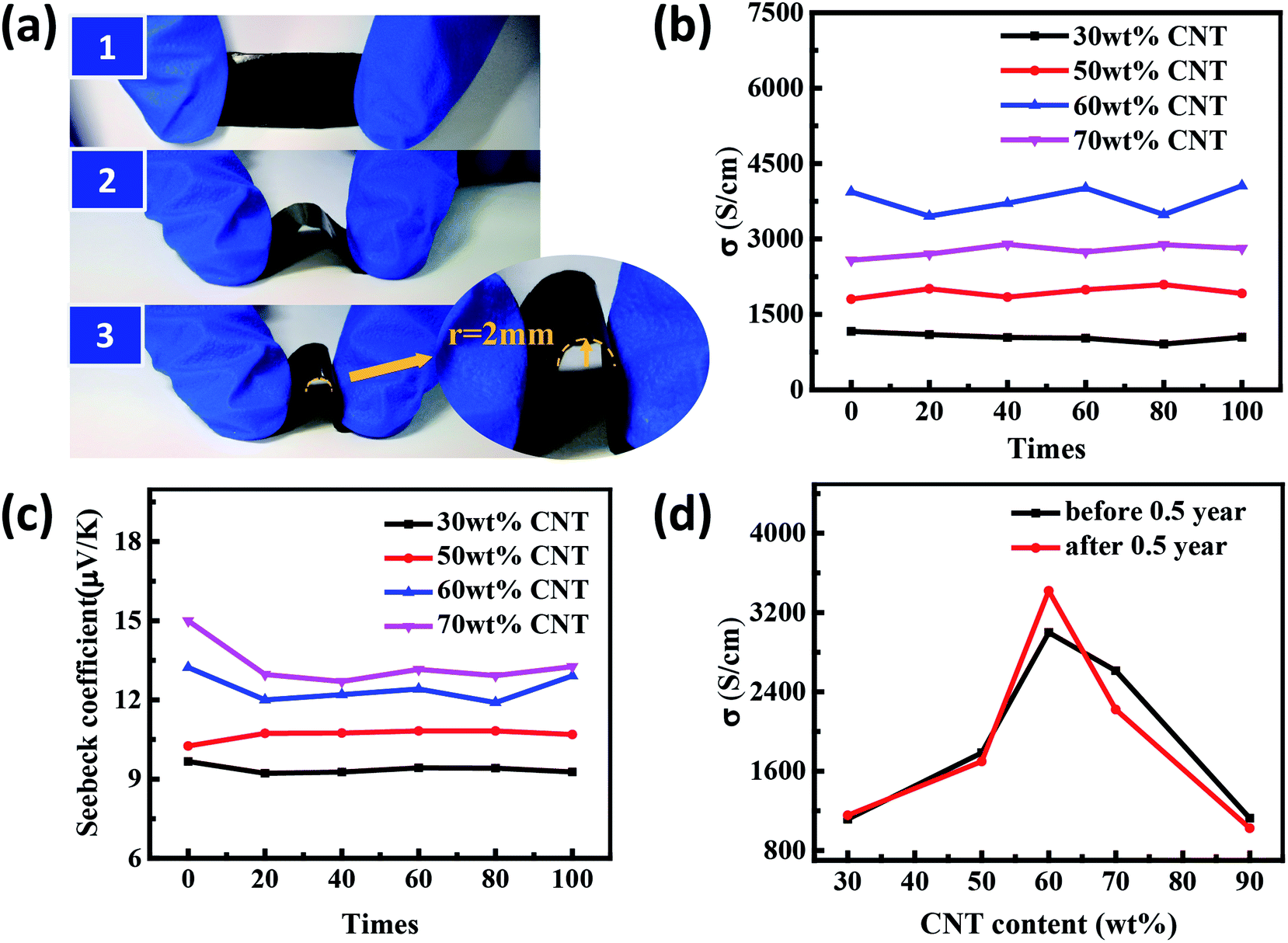 | ||
| Fig. 9 (a) Schematic of bending experiment: continuous repetition of 1, 2, and 3; bending radius r = 2 mm in enlarged view. (b) The changes in electrical conductivity and (c) Seebeck coefficient of hybrid films as a function of blending cycle times. (d) The conductivity of the composite films before and after half a year. | ||
4. Conclusions
In summary, we have demonstrated the influence of the molecular weight and structure of polyaniline at different polymerization times on the film formation and thermoelectric properties. The SEM and GPC analysis results showed that the film-forming properties of PANI were closely related to its molecular weight and structural morphology. The SWCNTs/PANI composites that have different carbon nanotube content with PANI at 5 h polymerization time and those prepared under different polymerization times for PANI with 60 wt% carbon nanotube content were researched. The composites of ultrahigh conductivity and low Seebeck coefficient values were obtained. The electrical conductivity of SWCNTs/PANI composites increased with the increase in SWCNT content, reaching a peak value at 60 wt% SWCNT, and then decreased. The Seebeck coefficient increased monotonously and slightly with the increase in SWCNT content in the entire SWCNT content range. The maximum electrical conductivity of the hybrid film was up to ∼4000 S cm−1. A highly ordered PANI interface layer formed by the π–π conjugation contributes to the conduction performance of the composites. The PANI matrix at different polymerization times has minor effect on thermoelectric properties of SWCNTs/PANI composites, confirming the importance of interlayer for the conduction performance. The excellent mechanical and environmental stability of SWCNTs/PANI films make it possible to use directly for wearable materials. Our results can lead to deeper and more comprehensive understanding of the effects of materials on thermoelectric properties in the composite system.Conflicts of interest
There are no conflicts to declare.Acknowledgements
This study was financially supported by the National Natural Science Foundation of China (No. 51772016, 51272021, 51402010 and 51072013).References
- G. Chen, W. Xu and D. Zhu, J. Mater. Chem. C, 2017, 5, 4350–4360 RSC
.
- J. Zhao, D. Tan and G. Chen, J. Mater. Chem. C, 2016, 5, 47–53 RSC
- B. Russ, A. Glaudell, J. J. Urban, M. L. Chabinyc and R. A. Segalman, Nat. Rev. Mater., 2016, 1, 16050 CrossRef
- O. Bubnova and X. Crispin, Energy Environ. Sci., 2012, 5, 9345–9362 RSC
- Q. Zhang, Y. Sun, W. Xu and D. Zhu, Adv. Mater., 2014, 26, 6829–6851 CrossRef PubMed
- Y. Chen, Y. Zhao and Z. Liang, Energy Environ. Sci., 2015, 8, 401–422 RSC
- H. J. Lee, A. Gopinathan, H. J. Lee, C. Kim, J. W. Park and J. Choi, et al., Energy Environ. Sci., 2016, 9, 2806–2811 RSC
- J. Chen, L. Wang, X. Gui, Z. Lin, X. Ke and F. Hao, et al., Carbon, 2017, 114, 1–7 CrossRef
- T. Farrell, K. Wang, C. W. Lin and R. B. Kaner, Polymer, 2017, 129, 1–4 CrossRef
- Q. Yao, Q. Wang, L. Wang, Y. Wang, J. Sun and H. Zeng, et al., J. Mater. Chem. A, 2014, 2, 2634–2640 RSC
- S. Zhang, Z. Fan, X. Wang, Z. Zhang and J. Ouyang, J. Mater. Chem. A, 2018, 6, 7080–7708 RSC
- Q. Yao, L. Chen, W. Zhang, S. Liufu and X. Chen, ACS Nano, 2010, 4, 2445–2451 CrossRef PubMed
- M. Cochet, W. K. Maser and A. M. Benito, et al., Chem. Commun., 2001, 16, 1450–1451 RSC
- Z. Fan, P. Li, D. Du and J. Ouyang, Adv. Energy Mater., 2017, 7, 1602116 CrossRef
- Q. Wei, M. Mukaida, K. Kirihara, Y. Naitoh and T. Ishida, Materials, 2015, 8, 732–750 CrossRef PubMed
- O. Bubnova, Z. U. Khan, H. Wang, S. Braun, D. R. Evans and M. Fabretto, et al., Nat. Mater., 2014, 13, 190–194 CrossRef PubMed
- O. Bubnova, Z. U. Khan, A. Malti, S. Braun, M. Fahlman and M. Berggren, et al., Nat. Mater., 2011, 10, 429–433 CrossRef PubMed
- Q. Wei, M. Mukaida, K. Kirihara, Y. Naitoh and T. Ishida, Appl. Phys. Express, 2014, 7, 031601 CrossRef
- G. P. Moriarty, J. N. Wheeler, C. Yu and J. C. Grunlan, Carbon, 2012, 50, 885–895 CrossRef
- Q. Wang, Q. Yao, J. Chang and L. Chen, J. Mater. Chem., 2012, 22, 17612–17618 RSC
- Y. Wang, J. Yang, L. Wang, K. Du, Q. Yin and Q. Yin, ACS Appl. Mater. Interfaces, 2017, 9, 20124–20131 CrossRef PubMed
- L. Wang, Q. Yao, B. Hui, F. Huang, Q. Wang and L. Chen, J. Mater. Chem. A, 2015, 3, 7086–7092 RSC
- H. Ju and J. Kim, ACS Nano, 2016, 10, 5730–5739 CrossRef PubMed
- R. Tian, C. Wan, Y. Wang, Q. Wei, T. Ishida and A. Yamamoto, et al., J. Mater. Chem. A, 2016, 5, 564–570 RSC
- Y. Wang, S. Zhang and Y. Deng, J. Mater. Chem. A, 2016, 4, 3554–3559 RSC
- J. Xiong, L. Wang, J. Xu, C. Liu, W. Zhou and H. Shi, et al., J. Mater. Sci.: Mater. Electron., 2016, 27, 1769–1776 CrossRef
- Q. Jiang, X. Lan and C. Liu, et al., Mater. Chem. Front., 2018, 2, 679–685 RSC
- H. Song, C. Liu and J. Xu, et al., RSC Adv., 2013, 3, 22065–22071 RSC
- F. Jiang, L. Wang and C. Li, et al., J. Polym. Res., 2017, 24, 68 CrossRef
- Q. Yao, Q. Wang, L. Wang and L. Chen, Energy Environ. Sci., 2014, 7, 3801–3807 RSC
- C. Meng, C. Liu and S. Fan, Adv. Mater., 2010, 22, 535–539 CrossRef PubMed
- Y. Wang, C. Yu, M. Sheng, S. Song and Y. Deng, Adv. Mater. Interfaces, 2018, 7, 1701168 CrossRef
- L. Wang, Q. Yao, W. Shi, S. Qu and L. Chen, Mater. Chem. Front., 2016, 1, 741–748 RSC
- H. Ju and J. Kim, Chem. Eng. J., 2016, 297, 66–73 CrossRef
- Q. Yao, L. Chen, X. Xu and C. Wang, Chem. Lett., 2005, 34, 522–523 CrossRef
- Y. J. Gelbstein, Appl. Phys., 2009, 105, 129–229 Search PubMed
- N. E. Coates, S. K. Yee and B. Mcculloch, et al., Adv. Mater., 2013, 25, 1629–1633 CrossRef PubMed
- C. Dun, C. A. Hewitt, H. Huang, J. Xu, D. S. Montgomery and W. Nie, et al., ACS Appl. Mater. Interfaces, 2015, 7, 7054–7059 CrossRef PubMed
- F. Jiang, J. Xiong, W. Zhou, C. Liu, L. Wang and F. Zhao, et al., J. Mater. Chem. A, 2016, 4, 5265–5273 RSC
- J. Xiong, F. Jiang, S. Hui, J. Xu, C. Liu and W. Zhou, et al., ACS Appl. Mater. Interfaces, 2015, 7, 14917–14925 CrossRef PubMed
- L. Wang, Q. Yao, S. Qu, W. Shi and L. Chen, Org. Electron., 2016, 39, 146–152 CrossRef
Footnote |
| † Electronic supplementary information (ESI) available. See DOI: 10.1039/c8ra04863k |
| This journal is © The Royal Society of Chemistry 2018 |