 Open Access Article
Aligned N-doped carbon nanotube bundles with interconnected hierarchical structure as an efficient bi-functional oxygen electrocatalyst†
Weiliang Tianac,
Cheng Wange,
Ruida Chenab,
Zhao Caia,
Daojin Zhouab,
Yongchao Haoa,
Yingna Changab,
Nana Hanb,
Yaping Lia,
Junfeng Liu a,
Feng Wang
 *a,
Wen Liu
 *a,
Haohong Duan*d and
Xiaoming Sun
 ab
ab
aState Key Laboratory of Chemical Resource Engineering, Beijing 100029, P. R. China. E-mail: wenliu@mail.buct.edu.cn; wangf@mail.buct.edu.cn
bSchool of Energy, Beijing Advanced Innovation Center for Soft Matter Science, Beijing University of Chemical Technology, Beijing 100029, P. R. China
cKey Laboratory of Chemical Resource Engineering in South Xinjiang, College of Life Science, Tarim University, Alar 843300, China
dChemistry Research Laboratory, Department of Chemistry, University of Oxford, 12 Mansfield Road, Oxford, OX1 3TA, UK. E-mail: haohong.duan@chem.ox.ac.uk
eChinese Research Academy of Environmental Sciences, Beijing 100012, China
First published on 19th July 2018
Abstract
The fabrication of cost effective and efficient electrocatalysts with functional building blocks to replace noble metal ones is of great importance for energy related applications yet remains a great challenge. Herein, we report the fabrication of a hierarchical structure containing CNTs/graphene/transition-metal hybrids (h-NCNTs/Gr/TM) with excellent bifunctional oxygen electrocatalytic activity. The synthesis was rationally designed by the growth of shorter nitrogen-doped CNTs (S-NCNTs) on longer NCNTs arrays (L-NCNTs), while graphene layers were in situ generated at their interconnecting sites. The hybrid material shows excellent OER and ORR performance, and was also demonstrated to be a highly active bifunctional catalyst for Zn–air batteries, which could be due to rapid electron transport and full exposure of active sites in the hierarchical structure.
Introduction
Advanced energy storage technologies are highly required for the wide adoption of renewable energy and sustainable power supply. Zinc–air batteries, which use zinc metal as anode material and oxygen in air as cathode material, have aroused particular interest for their impressive high specific energy of 1218 W h kg−1 when compared with that of the prevalent lithium ion batteries of 250 W h kg−1.1 Although Zn–air batteries have great potentials to be used in consumer electronics and electric vehicles, their further development and commercial implementation still have to circumvent some problems, such as the sluggish oxygen redox kinetics, formation of zinc dendrites, heat release and electrolyte deterioration by CO2 invasion. Among all these obstacles, the slow oxygen redox kinetics cause limited power density output and low energy efficiency with huge hysteresis between the low discharge voltage (∼1.2 V) and the high charge voltage (2.0 V). To date, the most effective electro-catalysts for oxygen reduction reaction (ORR) and oxygen evolution reaction (OER) are all based on precious metals (Pt, Ru, Ir and their compounds).2 The high cost and resource scarcity of these precious metals have hindered their wide application in air electrodes. Therefore, the design and synthesis of efficient yet low cost bifunctional electrocatalysts which can propel both OER and ORR holds the key to achieve affordable high performance rechargeable Zn–air batteries.As low dimensional materials, carbon nanotubes (CNTs) and graphene (Gr) have shown potentials in a wide range of applications, from nanocomposites, energy and environmental devices to chemical sensors.3–7 Their electrochemical performances and catalytic activities can be further improved by heteroatom doping, such as nitrogen, sulphur and phosphorus, on sp2 carbon nanomaterials at the edges, surfaces, defects, or strained regions.8–10 Integration of carbon-encapsulated metal nanoparticles (NPs) into CNTs or Gr could also produce more active sites for the electrocatalysis such as oxygen reduction reaction (ORR).11,12 However, freestanding CNTs and Gr tend to agglomerate or re-stack due to the large surface energy and strong van der Waals interactions, which limits their intrinsic activity and performances.13 A typical strategy to overcome this limit is to assembly CNTs or Gr into a robust three-dimensional (3D) network. For example, CNTs sponges,14 graphene foams,15 graphene nanofibers,16 and aerogels17 have been reported and shown good electro-catalytic activity. Notably, 3D hierarchical composites of CNTs and Gr with strong interconnection have demonstrated their advantages in the applications of energy storage.18–20 Therefore, highly conductive nitrogen-doped 3D CNTs/Gr hybrids with encapsulated transition metal is a promising cathode materials for zinc–air batteries.21 However, the growth of CNTs in the hybrids is always achieved by chemical vapor deposition (CVD) method which limits large-scale production. In addition, the use of flammable carbon source (CH4, C2H2 and C2H4), toxic solvent (benzene) and corrosive nitrogen source (NH3) is also unwanted from environmental concern.22 Thus, it is in strong demand for a facile and green strategy to fabricate well-interconnected CNT/Gr hybrids with transition metal doping as bifunctional catalytic electrode for Zn–air batteries.
Herein, nitrogen-doped 3D hierarchical NCNTs/graphene/transition metal hybrids (h-NCNTs/Gr/TM) were fabricated by growing short NCNTs on pre-synthesized aligned long NCNTs bundles using dicyandiamide (DCDA) as both carbon and nitrogen sources, and a few-layers of graphene was in situ formed at their interconnection site. In the fabrication process, the heat expanded natural vermiculite was used as confining template for growth of well aligned N doped long carbon nanotubes. Thereafter, Co3O4/Fe3O4 NPs were highly dispersed on the aligned L-NCNTs, which is used for catalyzing the growth of short CNTs and also turn out to be CoFe alloy nanoparticles as active sites for electro-catalysis. The obtained h-NCNTs/Gr/TM showed enhanced activities of the oxygen reduction reaction (ORR) and oxygen evolution reaction (OER). Their activity and feasibility for applications were further demonstrated as an electrocatalyst for the ORR and OER in zinc–air battery, which show equally matched rate capability and stable cyclability compared with zinc–air battery based on commercial precious metal catalysts of 20% Pt/C + 10% Ru/C.
Experimental section
Materials
Heat expanded natural vermiculite (calcined at about 1000 °C) was purchased from the Xinjiang Yuli vermiculite Co. Ltd, China. 20% Nafion, 20 wt% IrO2/C, 20% Pt/C and (20% Pt/C + 10% Ru/C) were purchased from Sigma Aldrich. Ferrocene were obtained from Xilong Chemical Co., Ltd. Pyridine was purchased from Tianjin Fu Chen Chemical Reagents. Other materials were all of A.R. grade, purchased from Beijing Chemical Reagent Co., Ltd. All chemicals were used as received without any further purification.Synthesis of L-NCNTs
The expanded natural vermiculite (VMT) was impregnated into an aqueous solution of FeCl3·6H2O (5 g/100 ml) through stirring at low speed for 12 h at 60 °C. Subsequently, the formed uniform suspension was filtrated, washed, and dried at 110 °C for 12 h, and then the Fe/VMT catalyst for aligned CNTs growth was obtained. L-NCNTs are synthesized by CVD process using a pyrolysis system containing a dual-zone tube furnace with a reaction quartz tube (45 mm in diameter and 1500 mm in length). Typically, ferrocene was dissolved in pyridine to make a solution with concentration of 0.02 g mL−1. The obtained solution and Fe/VMT were placed into the center of low temperature and high temperature zone of a quartz tube in the dual-temperature zone tube furnace, respectively. The reactor was heated to 300 °C (low temperature zone) and 700 °C (high temperature zone) in 60 min in an atmosphere of Ar (100 sccm) from low temperature to high temperature zone. After a reaction of 220 min, the furnace was cooled to room temperature in flowing Ar. The as-prepared products were treated with a HCl (6.0 mol L−1) aqueous solution at 90 °C for 24 h and a HF (6.0 mol L−1) aqueous solution at 90 °C for another 24 h to remove the VMTsubstrate.23Synthesis of CoFeOx decorated L-NCNTs
The as-prepared L-NCNTs were saturated with an aqueous solution containing Co(NO3)2·6H2O (1 g mL−1) and Fe(NO3)3·6H2O (1 g mL−1), and then dried at 60 °C for 24 h. Finally, the resulting sample was heated to 280 °C for 3 h in an atmosphere of Ar (80 sccm) to obtain the Co3O4/Fe3O4/L-NCNTs.Synthesis of h-NCNTs/Gr/TM hybrids
The obtained Co3O4/Fe3O4/L-NCNTs (100 mg) were placed in a crucible followed by adding a uniform powder of dicyandiamide 1.50 g, which was finely mixed in an agate mortar. The above crucible was placed into tube furnace and heated to 800 °C for 1.5 h at a heating rate of 2 °C min−1 under flowing Ar atmosphere. The control sample synthesized by heating the mixture of ferrocene and dicyandiamide using similar procedure above without the addition of Co3O4/Fe3O4/L-NCNTs was donated as S-NCNTs-C.24Characterization
The morphologies and structures of materials were examined by using scanning electron microscopy (SEM) (Zeiss SUPRA 55), transmission electron microscopy (TEM) (Hitachi 800), and high-resolution TEM (HRTEM) (JEOL JEM-2100). Chemical compositions were determined by elemental analysis (vario EL cube V2.0.1). An ESCALAB 250 system (Thermo Electron) was used to collect X-ray photoelectron spectroscopy (XPS) data with Al Kα 300 W radiation. Powder X-ray diffraction (XRD) data were collected with a Shimadzu XRD-6000 diffractometer using monochromatic Cu Kα radiation (λ = 0.15418 nm) at 40 kV. Raman spectra were recorded on a Lab RAM ARAMIS Raman Spectrometer (HORIBA Jobin Yvon) and 633 nm laser acted as an excitation source. The N content was determined by Energy Dispersive Spectrometer (EDS). The loading value of Co was measured by using inductively coupled plasma-atom emission spectroscopy (ICP).Electrochemical measurements
All electrochemical measurements were performed on a standard three-electrode setup at room temperature. Rotating ring disk electrode (RRDE) studies were conducted in an electrochemical cell using a saturated calomel electrode (SCE) as the reference electrode, a Pt electrode as the counter electrode and the sample modified glassy carbon electrode (GCE) of RRDE as the working electrode. Prior to surface coating, the GCE was sequentially polished using 0.3 and 0.05 mm alumina slurry and then washed ultrasonically in water and ethanol for 5 minutes. The cleaned GCE was dried at room temperature for the succeeding modification. Before the start of each measurement, the 0.1 mol L−1 KOH electrolyte was bubbled with O2 for 30 min. A flow of O2 was maintained over the electrolyte during the measurement to ensure continuous O2 saturation. For the working electrode preparation, 5.0 mg h-NCNTs/Gr/TM nanocomposites and 20.0 μL Nafion solution (5 wt%) were dispersed in 1.0 mL of ethanol solution by sonication for at least 150 minutes. Then 10.0 μL of the catalyst slurry was dropped on the surface of polished GCE with 5.61 mm in diameter using a micro-injector and dried at room temperature. For all RRDE measurements, the electrode rotation was set at different speeds (400, 625, 900, 1225, 1600, 2025 and 2500 r.p.m.); the ring potential was held constantly at 1.5 V (vs. reversible hydrogen electrode, RHE). Cyclic voltammetry (CV) tests were evaluated in the oxygen saturated 0.1 mol L−1 KOH aqueous solutions at a sweep rate of 50 mV s−1. The linear sweep voltammetry (LSV) experiments were conducted in oxygen saturated 0.1 mol L−1 KOH solution at 1600 r.p.m. from 0 to −1 V for ORR and from 0 to 1 V for OER with a scan rate of 5 mV s−1, respectively. Commercially available Pt/C (20 wt%) and IrO2/C (20 wt%) modified GCEs were prepared in the same way.Zn–air battery was assembled with an air cathode prepared by coating a mixture of the activated charcoal and PTFE (weight ratio 7![[thin space (1/6-em)]](https://www.rsc.org/images/entities/char_2009.gif) :
:![[thin space (1/6-em)]](https://www.rsc.org/images/entities/char_2009.gif) 3) on the nickel mesh, followed with rolling together with another nickel mesh of 1 × 1 cm in size loaded with h-NCNTs/Gr/TM (2.0 mg cm−2). Such a fabricated cathode is separated by electrolyte from the zinc metal anode. Nickel meshes were used as the current collectors for both electrodes. 1.8 mL of 6.0 mol L−1 KOH electrolyte with zinc acetate (1 g/50 ml) was filled between the cathode and anode. 6.0 mol L−1 KOH electrolyte is generally employed in zinc–air batteries because of its high ionic conductivity.25
3) on the nickel mesh, followed with rolling together with another nickel mesh of 1 × 1 cm in size loaded with h-NCNTs/Gr/TM (2.0 mg cm−2). Such a fabricated cathode is separated by electrolyte from the zinc metal anode. Nickel meshes were used as the current collectors for both electrodes. 1.8 mL of 6.0 mol L−1 KOH electrolyte with zinc acetate (1 g/50 ml) was filled between the cathode and anode. 6.0 mol L−1 KOH electrolyte is generally employed in zinc–air batteries because of its high ionic conductivity.25
Results and discussion
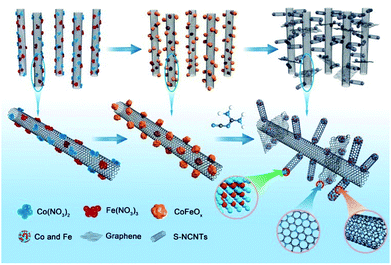
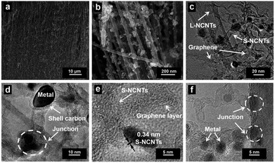
The fabrication process of the hierarchical structure of h-NCNTs/Gr/TM was illustrated in Fig. 1. Firstly, a super hydrophilic aligned L-NCNTs forest was synthesized by pyrolysing ferrocene and pyridine on layered vermiculite (VMT) (Fig. S1a and b†), via chemical vapor deposition (CVD), which is followed by acid (HCl and HF) treatment to remove VMT (Fig. S1c and d†).26 Secondly, Co3O4/Fe3O4 NPs were loaded on the aligned L-NCNTs by immersing the as-prepared aligned L-NCNTs into a mixed solution of Co(NO3)2 and Fe(NO3)3 for 0.5 h and then heating in air at 300 °C for 8 h. Lastly, S-NCNTs grow on the catalytic sites of Co3O4/Fe3O4 NPs with the formation of graphene at the interconnection between S-NCNTs and L-NCNTs. DCDA plays a bifunctional role in the fabrication process, which act not only as both carbon source and nitrogen source for the growth of nitrogen-doped S-NCNTs and Gr, but also as a reductant to reduce Co3O4/Fe3O4 NPs into CoFe alloy nanoparticles.The scanning electron microscopy (SEM) image shown in Fig. 2a reveals the successful synthesis of large-area L-NCNTs forests. Fig. 2b shows the SEM image of the composites of Co3O4/Fe3O4 NPs on L-NCNTs, in which the metal oxide nanoparticles with size of about 20–40 nm that would be reduced to CoFe alloy nanoparticles as catalysts for further carbon material growth. The morphology of h-NCNTs/Gr/TM was shown in Fig. 2c. As we can see, S-NCNTs with diameter of about 10 nm rooted from the CoFe catalyst nanoparticles. Graphene layers were also observed to encapsulate the CoFe alloy nanoparticles and also to interconnect between S-NCNTs and L-NCNTs. The hierarchical structure of h-NCNTs/Gr/TM hybrid was further shown Fig. 2d to f. Fig. 2d also shows an junction between the primary L-NCNTs and secondary S-NCNTs. Interestingly, the obtained S-NCNTs in the resulting h-NCNTs/Gr/TM exhibit a bamboo-like structure (Fig. 2d), which is mainly due to the incorporation of nitrogen atom into CNTs.15 The adjacent interlayer distance of S-NCNTs is about 0.34 nm. The diameter of CoFe NPs is about 10 nm, which is caged by thin carbon film shown in Fig. 2d and f. The mole ratio of Co![[thin space (1/6-em)]](https://www.rsc.org/images/entities/char_2009.gif) :
:![[thin space (1/6-em)]](https://www.rsc.org/images/entities/char_2009.gif) Fe in h-NCNTs/Gr/TM is about 1
Fe in h-NCNTs/Gr/TM is about 1![[thin space (1/6-em)]](https://www.rsc.org/images/entities/char_2009.gif) :
:![[thin space (1/6-em)]](https://www.rsc.org/images/entities/char_2009.gif) 1, as shown in Fig. S2.† For comparison, the short NCNTs sample (denoted as S-NCNTs-C) were also prepared by heating the mixture of ferrocene and dicyandiamide with similar procedure and same parameters (800 °C, 2 h), which contained L-NCNTs agglomerated together with an average diameter of 50 nm (Fig. S1f†).
1, as shown in Fig. S2.† For comparison, the short NCNTs sample (denoted as S-NCNTs-C) were also prepared by heating the mixture of ferrocene and dicyandiamide with similar procedure and same parameters (800 °C, 2 h), which contained L-NCNTs agglomerated together with an average diameter of 50 nm (Fig. S1f†).
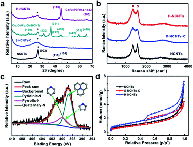
X-ray diffraction (XRD) patterns for the obtained samples are shown in Fig. 3a. Three typical diffraction peaks of graphitic carbon at 2θ = 26.2, 43.0 and 44.6 deg were observed for L-NCNTs, indicating the existence of CNTs (PDF#41-1487). After loading metal oxides onto the surface of the L-NCNTs, new diffraction peaks attributed to Co3O4 (PDF#43-1003) and Fe3O4 (PDF#26-1136) were detected. These peaks were not observed in the XRD pattern of h-NCNTs/Gr/TM, and a series of diffractions of CoFe (PDF#44-1433) were detected, suggesting a total reduction of the metal oxides. Raman spectra were used to determine the bonding features of carbon materials in the composites. As shown in Fig. 3b, the D- and G-bands of carbon for all three samples appear at 1353 and 1584 cm−1, respectively, which could be assigned to the defects and disorder-induced mode and in-planar E2g zone-center mode.27,28 There is no obvious shift of the D- and G-bands of h-NCNTs/Gr/TM hybrid after the growth of S-NCNTs. The intensity ratios of the D- and G-bands (ID/IG) for L-NCNTs and h-NCNTs/Gr/TM are 0.94 and 1.07, respectively, indicating a higher degree of defects in h-NCNT/Gr/TM hybrid. The surface chemistry of h-NCNTs/Gr/TM hybrids was further evaluated by X-ray photoelectron spectroscopy (XPS). As displayed in Fig. S3 and Table S1,† five types of elements, C, O, N, Co and Fe were detected and N content increased from 8.0 at% for L-NCNTs to 10.0 at% for h-NCNTs/Gr/TM hybrids. Moreover, the Fe, Co content in h-NCNTs/Gr/TM hybrids is 0.97 at% and 1.22 at%, respectively. The high resolution XPS spectra of N 1s (Fig. 3c) show peaks around 398.8, 400.1 and 401.2 eV, which indicate the presence of three types of N species as pyridinic, pyrrolic and quaternary N, respectively.29,30 In addition, the contents of pyridinic N were found to increase with the increasing N content from L-NCNTs to the h-NCNTs/Gr/TM.
The N2-adsorption/desorption measurements were carried out to study the surface area and porosity of h-NCNTs/Gr/TM hybrid, with pristine L-NCNTs and S-NCNTs-C as reference samples (Fig. 3d). Typical IV isotherms with H3-type hysteresis loops (P/Po > 0.4) are observed for the h-NCNTs/Gr/TM and S-NCNTs-C, indicating the presence of a mesoporous structure. This type of hysteresis loops does not exhibit any limiting adsorption at high P/Po region, which is commonly attributed to particle aggregates with slit-shaped pores. Moreover, the h-NCNTs/Gr/TM with the hierarchical structure exhibits a large apparent specific surface area (95 m2 g−1) and total pore volume (0.25 cm3 g−1) calculated by the Brunauer–Emmett–Teller (BET) method, which is much higher than that of the other two samples (Table S2, ESI†). By virtue of its large surface area and the unique hierarchical porous structure, the h-NCNTs/Gr/TM composite material may provide more active site for electrocatalysis.
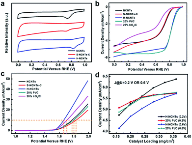
The electrocatalytic ORR and OER activities of these samples were evaluated in a three-electrode electrochemical cell with a rotating ring-disk electrode (RRDE) as the working electrode under O2-saturated conditions. Fig. 4a shows the cyclic voltammetry (CV) curves of L-NCNTs, S-NCNTs-C and h-NCNTs/Gr/TM in a 0.1 M KOH solution. For L-NCNTs and S-NCNTs-C electrodes, a single cathodic reduction peak was present at 0.74 V and 0.72 V (vs. RHE), respectively. In contrast, the h-NCNTs/Gr/TM hybrids showed more positive reduction peak potential (0.82 V) and higher peak current density than that of L-NCNTs and S-NCNTs-C electrodes. To gain further insights into the ORR performance of these samples, LSV measurements were also performed on RRDE at a rotation rate of 1600 r.p.m. As shown in Fig. 4b, the h-NCNTs/Gr/TM has higher steady-state diffusion limiting current than that of the L-NCNTs and S-NCNTs-C, which is consistent with the above CV results. In addition, the onset potential and current density for h-NCNTs/Gr/TM is close to that of a commercial Pt/C catalyst (20 wt%) as shown in Fig. 4b. The polarization curves were depicted into Tafel plots as presented in Fig. S4a.† The Tafel slope of h-NCNTs/Gr/TM is 58.1 mV dec−1, which is close to 20% Pt/C (59.5 mV dec−1), and is much lower than the that of 20% IrO2/C (87.5 mV dec−1), L-NCNTs (74.6 mV dec−1) and S-NCNTs-C (93.8 mV dec−1). Koutecký–Levich (K–L) plots of j−1 versus ω−1/2 derived from the polarization curves at the rotating speed ranging from 400 to 2500 r.p.m. is linear, suggesting first-order reaction kinetics toward the concentration of dissolved oxygen (Fig. S4c and d†).31 According to the K–L equation, the average electron number (ne) per oxygen molecule transferred during ORR was calculated to be around 4.0 at the potential ranging from 0.75 to 0.85 V, which indicates that the ORR by using h-NCNTs/G/TM follows a four-electron-transfer reaction to reduce oxygen directly into OH−.32
The OER activity of h-NCNTs/Gr/TM was also examined in a 0.1 M KOH solution. As shown in Fig. 4c, the h-NCNTs/Gr/TM sample exhibits the best OER performance among all the tested electrocatalysts. The formation of hierarchical structure with heteroatom doping and uniformly distributed CoFe NPs in h-NCTs/Gr/TM obviously improve the catalytic activity as compared to L-NCNTs and S-NCNTs-C. Moreover, h-NCNTs/Gr/TM hybrid is even superior to the IrO2/C catalyst, demonstrating better OER catalytic activity in alkaline electrolyte. The OER kinetics of L-NCTs, S-NCTs-C and h-NCNTs/Grr/TM were further evaluated by their corresponding Tafel plots. Fig. S4b† shows that the Tafel slope of h-NCNTs/Gr/TM (82.6 mV dec−1) is lower than other samples. The small Tafel slope reveals that the incorporation of CoFe NPs and short S-NCNTs can effectively promote the OER kinetics, which is further verified by the electrochemical impedance spectra (EIS). As shown in Fig. S5,† the charge transfer resistance (Rct) in the lower frequency region and interfacial impedance (Ri) in the higher frequency region of h-NCNTs/Gr/TM are obviously decreased as compared with L-NCTs and S-NCTs-C.
The active area of catalyst and transportation of dissolved O2 in the catalyst layer are important for ORR at a given rotation rate (schematically shown in Fig. S6†). The densely packed diffusion layer in Pt/C catalyst makes it only have few voids as electrolyte reservoir. It is also very hard for ions to penetrate electrode within the poor porous structure, therefore, only a small amount of catalyst surface would contribute to the ORR due to O2 and ions deficiency. In the contrast, the naturally formed void space between mutual supporting hierarchical structures of h-NCNTs/Gr/TM could reserve a lot of electrolyte as reservoir and provide broad pathways for dissolved O2. In order to investigate the importance of hierarchical structures in catalyst membrane layer, catalytic activities of different catalyst loadings were investigated. Fig. S7a† displays the ORR performance of Pt/C catalyst at different catalyst loadings. The diffusion limiting current densities of Pt/C catalyst demonstrate major advances at low catalyst loading of 0.16 and 0.20 mg cm−2, but decline after the areal loading slightly increased over 0.28 mg cm−2. On the contrary, the hierarchical h-NCNTs/Gr/TM sample, which is capable of reserving channels for ion and O2 transport at very high catalyst loading densities, suffers negligible current density payoff until areal catalyst loading reaching as high as 0.32 mg cm−2, as shown in Fig. S7b.† Remarkably, the current densities of h-NCNTs/Gr/TM and Pt/C electrodes both increase gradually at low catalyst loadings; but the current density of Pt/C electrode trend to level off with catalyst loading at 0.24 and 0.28 mg cm−2 while current of h-NCNTs/Gr/TM keep increasing (Fig. 4d, S7c and d), which further highlight the advantages of the hierarchical structures in h-NCNTs/Gr/TM.
The stability and possible crossover effects of electrocatalysts are both important parameters for the practical use in fuel cells or water electrolysis.33–36 The chronoamperometric result of h-NCNTs/Gr/TM for ORR exhibits a very slow attenuation, and 93.9% of catalytic current still retains after 10![[thin space (1/6-em)]](https://www.rsc.org/images/entities/char_2009.gif) 000 s. Furthermore, the chronoamperometric study of the electrocatalysts for OER shows that the stability of the h-NCNTs/G/TM is better than that of IrO2/C (20%), showing a very slow attenuation and 96.5% of current retention after 10
000 s. Furthermore, the chronoamperometric study of the electrocatalysts for OER shows that the stability of the h-NCNTs/G/TM is better than that of IrO2/C (20%), showing a very slow attenuation and 96.5% of current retention after 10![[thin space (1/6-em)]](https://www.rsc.org/images/entities/char_2009.gif) 000 s (Fig. 5b).37 Thereafter, methanol was introduced into the O2-saturated electrolyte for both h-NCNTs/Gr/TMs and a commercial Pt/C catalyst.38 It can be seen from Fig. 5a that there is no noticeable change in the ORR current of the h-NCNTs/Gr/TM electrode after the addition of 1.5 ml of methanol at 5000 s. In contrast, the ORR current of the Pt/C catalyst decreases sharply, which indicate that h-NCNTs/Gr/TM has high ORR selectivity, and a strong ability of avoiding crossover effect. These results further confirm the potential of h-NCNTs/Gr/TM in the application of direct methanol and alkaline fuel cells.
000 s (Fig. 5b).37 Thereafter, methanol was introduced into the O2-saturated electrolyte for both h-NCNTs/Gr/TMs and a commercial Pt/C catalyst.38 It can be seen from Fig. 5a that there is no noticeable change in the ORR current of the h-NCNTs/Gr/TM electrode after the addition of 1.5 ml of methanol at 5000 s. In contrast, the ORR current of the Pt/C catalyst decreases sharply, which indicate that h-NCNTs/Gr/TM has high ORR selectivity, and a strong ability of avoiding crossover effect. These results further confirm the potential of h-NCNTs/Gr/TM in the application of direct methanol and alkaline fuel cells.
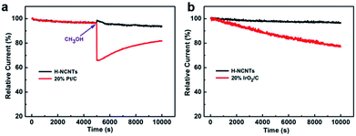 | ||
| Fig. 5 The stability and methanol tolerance tests for ORR (a), and durability tests for OER (b) of h-NCNTs/Gr/TM at 1600 r.p.m. speed of rotating disc electrode in 0.1 M KOH solution. | ||
The overvoltage between ORR and OER indicates the loss of efficiency and it is an important parameter to evaluate the bifunctional electrocatalytic activity (Table 1).39 The ORR activities of the catalysts were derived at a potential corresponding to −3 mA cm−2 of the current density, while the OER performance were measured by the potential at a current density of 10 mA cm−2. The potential difference between OER and ORR of h-NCNTs/Gr/TM is just 0.845 V, which is much smaller than that in Pt/C (1.001 V) and IrO2/C (1.26 V). The excellent bifunctional performance of h-NCNTs/Gr/TM implies its great potential in the applications for metal–air batteries, fuel cells and water splitting.
| Catalysts | EORR/V (−3 mA cm−2) | EOER/V (10 mA cm−2) | ΔE/V (EOER − EORR) |
|---|---|---|---|
| h-NCNTs/Gr/TM | 0.815 | 1.660 | 0.845 |
| L-NCNTs | 0.665 | 1.775 | 1.110 |
| S-NCNTs-C | 0.665 | 1.830 | 1.165 |
| Pt/C | 0.816 | 1.817 | 1.001 |
| IrO2/C | 0.445 | 1.705 | 1.260 |
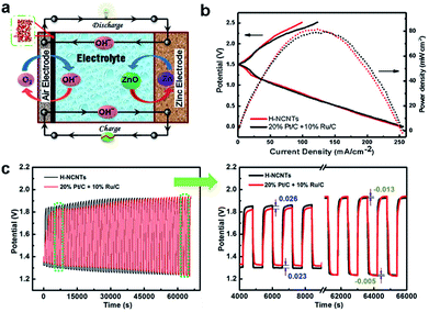
Encouraged by the excellent bifunctional performance of h-NCNTs/Gr/TM in ORR and OER, a prototype of Zn–air battery was assembled to examine the practical capability of h-NCNTs/Gr/TM electrode (Fig. 6a). Ambient air was used in our experiments other than pure O2, which is more acceptable to practical applications. The charge and discharge polarization behavior was firstly measured with reference to the 20% Pt/C + 10% Ru/C catalytic electrode. As displayed in Fig. 6b, the battery performance of h-NCNTs/Gr/TM is comparable to that of the 20% Pt/C + 10% Ru/C cathode at 1.0–1.5 V (up to 57 mA cm−2) for discharging and 1.5–2.2 V (up to 42 mA cm−2) for charging. In addition, a power density of 81.76 mW cm−2 is exhibited by h-NCNTs/Gr/TM, which is higher than 78.42 mW cm−2 for the reference. The cycling tests of rechargeable Zn–air batteries using h-NCNTs/Gr/TM or 20% Pt/C + 10% Ru/C were shown in Fig. 6c. After 110 cycles in 6.0 M KOH, the final charge/discharge potentials of h-NCNTs/Gr/TM and 20% Pt/C + 10% Ru/C are 1.92/1.23 and 1.94/1.22 V, respectively, whereas the initial values are 1.84/1.32 and 1.86/1.35 V, respectively. The primary zinc–air batteries were also examined by the galvanostatic discharge curves. The results shown in Fig. S8a† clearly reveal that battery with h-NCNTs/Gr/TM has higher voltage plateau (ca. 1.25 V) than that of battery with 20% Pt/C + 10% Ru/C (ca. 1.15 V) at the current density of 7 mA cm−2.40 When normalized to the mass of consumed Zn, the battery with h-NCNTs/Gr/TM cathode exhibit a specific capacity of 618 mA h gZn−1 at current densities of 7 mA cm−2 (Fig. S8b†), corresponding to a gravimetric energy density of 741 W h gZn−1. The performance of our Zn–air battery was again compared to some carbon based systems reported recently (see the ESI, Table S3† for details). The advanced electrochemical performances of h-NCNTs/Gr/TM for both ORR and Zn–air battery can be attributed to the factors that transition metal embedded in the N doped carbon with high activity and the three dimensional structure of CNT/Gr hybrids provides efficient mass and electron transference.
Conclusions
In summary, hierarchical electrocatalyst composing N doped carbon nanotube/graphene/transition-metal hybrid (h-NCNTs/G/TM) was successfully fabricated. The transition-metal nanoparticles are used to catalyze the growth of short NCNTs and also for providing catalytically active sits. The graphene was in situ and interconnect between S-NCNTs and L-NCNTs. This hierarchical structure shows excellent OER and ORR performance, and further makes it an efficient bifunctional catalyst for Zn–air batteries with reduced overpotential of 0.69 V after 110 cycles at 5 mA cm−2. We believe that the hierarchical structure design with functional building blocks can facilitate the preparation of other advanced functional materials, which combing the advantages of the properties of functional components, for wide applications as Li-ion batteries, supercapacitors, sensors, catalysis for fuel cells, and clean energy storage.Conflicts of interest
There are no conflicts to declare.Acknowledgements
The authors thank Prof. Liming Dai for his helpful discussion. This work was supported by NSFC, Beijing Natural Science Foundation (2172042), 973 Program (2014CB932104), National Key Research and Development Project (2016YFF0204402, 2016YFC0801302), the Program for Changjiang Scholars, and Innovative Research Team in the University, the Fundamental Research Funds for the Central Universities, Beijing Engineering Center for Hierarchical Catalysts, the long term subsidy mechanism from the Ministry of Finance and the Ministry of Education of PRC, and Petro China Innovation Foundation.Notes and references
- J. Park, M. Park, G. Nam, J. Lee and J. Cho, Adv. Mater., 2015, 27, 1396 CrossRef PubMed.
- Y. J. Wang, N. Zhao, B. Fang, H. Li and X. T. Bi, Chem. Rev., 2015, 115, 3433 CrossRef PubMed.
- M. F. L. De Volder, S. H. Tawfick, R. H. Baughman and A. J. Hart, Science, 2013, 339, 535 CrossRef PubMed.
- Y. Yan, Y. X. Yin, Y. G. Guo and L. J. Wan, Adv. Energy Mater., 2014, 4, 1079 Search PubMed.
- X. Huang, X. Qi, F. Boey and H. Zhang, Chem. Soc. Rev., 2012, 41, 666 RSC.
- Q. Shi, Y. D. Wang, Z. M. Wang, Y. P. Lei, B. Wang, N. Wu, C. Han, S. Xie and Y. Z. Gou, Nano Res., 2016, 9, 317 CrossRef.
- C. Zhou, J. Kong, E. Yenilmez and H. Dai, Science, 2000, 290, 1552 CrossRef PubMed.
- K. Gong, F. Du, Z. Xia, M. Durstock and L. Dai, Science, 2009, 323, 760 CrossRef PubMed.
- L. Song, Z. Liu, A. L. M. Reddy, N. T. Narayanan, J. Taha-Tijerina, J. Peng, G. H. Gao, J. Lou, R. Vajtai and P. M. Ajayan, Adv. Mater., 2012, 24, 4878 CrossRef PubMed.
- G. Wu, K. L. More, C. M. Johnston and P. Zelenay, Science, 2011, 332, 443 CrossRef PubMed.
- H. T. Chung, J. H. Won and P. Zelenay, Nat. Commun., 2013, 4, 54 Search PubMed.
- S. Lu and Z. Zhuang, Sci. China Mater., 2016, 59, 217 CrossRef.
- C. Tang, Q. Zhang, M. Zhao, J. Huang, X. Cheng, G. Tian, H. Peng and F. Wei, Adv. Mater., 2014, 26, 6100 CrossRef PubMed.
- X. Gui, Z. Zeng, Y. Zhu, H. Li, Z. Lin, Q. Gan, R. Xiang, A. Cao and Z. Tang, Adv. Mater., 2014, 26, 1248 CrossRef PubMed.
- H. Hu, Z. B. Zhao, W. B. Wan, Y. Gogotsi and J. S. Qiu, Adv. Mater., 2013, 25, 2219 CrossRef PubMed.
- Z. L. Dong, C. C. Jiang, H. H. Cheng, Y. Zhao, G. Q. Shi, L. Jiang and L. T. Qu, Adv. Mater., 2012, 24, 1856 CrossRef PubMed.
- M. A. Worsley, P. J. Pauzauskie, T. Y. Olson, J. Biener, J. H. Satcher and T. F. Baumann, J. Am. Chem. Soc., 2010, 132, 14067 CrossRef PubMed.
- W. Wang, I. Ruiz, S. Guo, Z. Favors, H. H. Bay, M. Ozkan and C. S. Ozkan, Nano Energy, 2014, 3, 113 CrossRef.
- M. Q. Zhao, Q. Zhang, J. Q. Huang and F. Wei, Adv. Funct. Mater., 2012, 22, 675 CrossRef.
- U. N. Maiti, W. J. Lee, J. M. Lee, Y. Oh, J. Y Kim, J. E. Kim, J. Shim, T. H. Han and S. O. Kim, Adv. Mater., 2014, 26, 40 CrossRef PubMed.
- L. Sun, W. Kong, Y. Jiang, H. Wu, K. Jiang, J. Wang and S. Fan, J. Mater. Chem. A, 2014, 3, 5305 RSC.
- Y. Ito, Y. Tanabe, H. J. Qiu, K. Sugawara, S. Heguri, N. H. Tu, K. K. Huynh, T. Fujita, T. Takahashi, K. Tanigaki and M. Chen, Angew. Chem., Int. Ed., 2014, 53, 4822 CrossRef PubMed.
- W. Tian, H. Li, B. Qin, Y. Xu, Y. Hao, Y. Li, G. Zhang, J. Liu, X. Sun and X. Duan, J. Mater. Chem. A, 2017, 5, 7103 RSC.
- Y. Ding, P. Kopold, K. Hahn, P. A. van Aken, J. Maier and Y. Yu, Adv. Funct. Mater., 2015, 26, 1681 Search PubMed.
- S. K. Singly, V. M. Dhavale and S. Kurungot, ACS Appl. Mater. Interfaces, 2015, 7, 442 CrossRef PubMed.
- Z. Yang, X. H. Chen, H. G. Nie, K. Zhang, W. H. Li and B. Yi, Nanotechnology, 2008, 19, 2905 Search PubMed.
- S. Deng, Y. Zhang, A. H. Brozena, M. L. Mayes, P. Banerjee, W. A. Chiou, G. W. Rubloff, G. C. Schatz and Y. Wang, Nat. Commun., 2011, 2, 3821 Search PubMed.
- C. H. Kuo, W. Li, W. Song, Z. Luo, A. S. Poyraz, Y. Guo, A. W. K. Ma, S. L. Suib and J. He, ACS Appl. Mater. Interfaces, 2014, 6, 11311 CrossRef PubMed.
- J. Song, T. Xu, M. L. Gordin, P. Zhu, D. Lv, Y. B. Jiang, Y. Chen, Y. Duan and D. Wang, Adv. Funct. Mater., 2014, 24, 1243 CrossRef.
- R. M. Yadav, J. Wu, R. Kochandra, L. Ma, C. S. Tiwary, L. Ge, G. Ye, R. Vajtai, J. Lou and P. M. Ajayan, ACS Appl. Mater. Interfaces, 2015, 7, 11991 CrossRef PubMed.
- Y. Meng, D. Voiry, A. Goswami, X. Zou, X. Huang, M. Chhowalla, Z. Liu and T. Asefa, J. Am. Chem. Soc., 2014, 136, 13554 CrossRef PubMed.
- G. Zhang, Y. Xu, L. Wang, J. Wang, Y. Kuang and X. Sun, Sci. China Mater., 2015, 58, 534 CrossRef.
- S. Chen, J. Duan, M. Jaroniec and S. Z. Qiao, Adv. Mater., 2014, 26, 2925 CrossRef PubMed.
- Z. Wen, S. Ci, Y. Hou and J. Chen, Angew. Chem., Int. Ed., 2014, 53, 6496 CrossRef PubMed.
- C. Tian, Q. Zhang, B. Zhang, Y. Jin, J. Huang, D. S. Su and F. Wei, Adv. Funct. Mater., 2014, 24, 5956 CrossRef.
- Y. Zhao, R. Nakamura, K. Kamiya, S. Nakanishi and K. Hashimoto, Nat. Commun., 2013, 4, 105 Search PubMed.
- S. Liu, L. Li, H. S. Ahnb and A. Manthiram, J. Mater. Chem. A, 2015, 3, 11615 RSC.
- Z. Liu, G. Zhang, Z. Lu, X. Jin, Z. Chang and X. Sun, Nano Res., 2013, 6, 293 CrossRef.
- A. Aijaz, J. Masa, C. Rosler, W. Xia, P. Weide, A. J. Botz, R. A. Fischer, W. Schuhmann and M. Muhler, Angew. Chem., Int. Ed., 2016, 55, 4087 CrossRef PubMed.
- X. Liu, M. Park, M. G. Kim, S. Gupta, G. Wu and J. Cho, Angew. Chem., Int. Ed., 2015, 54, 9654 CrossRef PubMed.
Footnote |
| † Electronic supplementary information (ESI) available. See DOI: 10.1039/c8ra03994a |
| This journal is © The Royal Society of Chemistry 2018 |

