 Open Access Article
Tuning the mechanical properties of silicene nanosheet by auxiliary cracks: a molecular dynamics study†
Shahriar Muhammad Nahida,
Shahriar Nahiana,
Mohammad Motalab *a,
Tawfiqur Rakibb,
Satyajit Mojumder
 a and
Md Mahbubul Islam
 c
c
aDepartment of Mechanical Engineering, Bangladesh University of Engineering and Technology, Dhaka-1000, Bangladesh. E-mail: abdulmotalab@me.buet.ac.bd
bDepartment of Mechanical and Chemical Engineering, Islamic University of Technology, Board Bazar, Gazipur-1704, Bangladesh
cSchool of Materials Engineering, Purdue University, West Lafayette, IN-47907, USA
First published on 28th August 2018
Abstract
Silicene has become a topic of interest nowadays due to its potential application in various electro-mechanical nanodevices. In our previous work on silicene, fracture stresses of single crystal and polycrystalline silicene have been investigated. Existence of defects in the form of cracks reduces the fracture strength of silicene nanosheets to a great extent. In this study, an engineering way has been proposed for improving the fracture stress of silicene nanosheets with a pre-existing crack by incorporating auxiliary cracks symmetrically in a direction perpendicular to the main crack. We call this mechanism the “Failure shielding mechanism”. An extensive molecular dynamics simulation based analysis has been performed to capture the atomic level auxiliary crack-main crack interactions. It is found that the main crack tip stress distribution is significantly changed with the presence of auxiliary cracks for loading along both armchair and zigzag directions. The effects of temperature and the crack propagation speed of silicene have also been studied. Interestingly, in the case of loading along the zigzag direction, SW defect formation is observed at the tip of main crack. This leads to a reduction of the tip stress resulting in a more prominent failure shielding in case of zigzag loading than in armchair loading. Moreover, the position and length of the cracks as well as the loading directions have significant impacts on the tip stress distribution. Finally, this study opens the possibilities of strain engineering for silicene by proposing an engineering way to tailor the fracture strength of silicene.
1. Introduction
Two dimensional (2D) materials are a matter of interest nowadays because of their exceptional and novel physical properties.1–5 After the rise of graphene,6 the exceptional mechanical,7,8 thermal9 and electrical properties10–14 of 2D materials, due to their two dimensional π bonding network, have spurred tremendous research interest.6,15 Silicene, a monolayer of silicon (Si) atoms arranged in hexagonal honeycomb lattice, is a 2D analogue of graphene.16,17Previously, density functional theory (DFT) calculations have been used to investigate the stability of the 2D honeycomb lattice of Si atoms.18–20 Besides, silicene has been synthesized on Ag, ZrB2 and Ir substrates by depositing Si atoms.21–25 Likewise, silicene is also a semiconductor with zero band gap.26 However, π electrons of silicene are more active than graphene. Therefore, electronic properties of silicene can be tuned by applying strain to design highly productive nanodevices.27 Therefore, it is of a great importance to investigate the mechanical behavior of silicene under applied strain.
Even though the pristine structure of silicene has a very high fracture strength,28,29 fracture toughness of silicene is significantly lower than most of the conventional engineering materials.30 This offers a challenge in the fabrication of silicene based nanoelectronic devices. In general, fabrication of 2D materials involve various structural flaws such as defects and cracks.16,31,32 These inherent flaws significantly reduce the ultimate stress of the materials because of the high local stress concentration region.29,30,33,34 Numerous investigations have been conducted to probe the fracture mechanism of 2D nanosheets with pre-existing cracks.7,35 Specifically, the failure mechanism of single crystal and nanocrystalline silicene have been extensively studied30,36 due to the challenge concerning the fabrication method. Yuan et al.29 investigated the mechanical properties of armchair silicene nanoribbons containing an edge crack using molecular dynamics (MD) simulations. The effects of edge crack length, strain rate, temperature on the fracture strength have been studied. Ding et al.33 investigated the effects of defects such as vacancies, crack and grain boundaries on the mechanical properties of silicene sheet. They found a linear decreasing relationship between the strength of silicene sheet and the defect parameters. From these studies, it is inevitable that the mechanical properties of silicene at nanoscale are significantly affected by the presence of pre-existing cracks. Therefore, it greatly necessitates to focus on finding an engineering solution to compensate for the decrement of mechanical properties. Previously, very few studies have been performed to elucidate various processes to increase the fracture strength of graphene by lattice trapping or crack arresting. These processes involve introduction of various topological defects in the structure37–41 which has a major drawback due to their inapplicability in the perfect lattices.19,20,42 Also, the fracture behavior of silicene is much different than graphene. Previously, Rakib et al.30 investigated the comparative mechanical properties and fracture toughness of graphene, silicene and hexagonal boron nitride. Chung et al.43 showed that unlike graphene, the stress in the silicene nanosheet is non-uniformly distributed due to the rearrangement of atoms in the silicene nanosheet via ring reorientation under applied strain. They also described the difference in crack propagation direction between silicene and graphene nanosheet.
In continuum fracture mechanics, it is well established that interactions of micro-cracks and voids with the crack can significantly alter the stress concentration around the crack tip.44,45 However, atomistic studies on multiple crack interaction are quite limited. Liu et al.46 investigated the crack void interaction in α-Fe and Dewapriya et al. showed that lattice trapping of graphene can be achieved by placing holes and multiple cracks around the crack tip.47,48 However, to the best of our knowledge, no such study has been conducted to provide any solution to increase the mechanical properties of silicene nanosheet containing pre-existing crack.
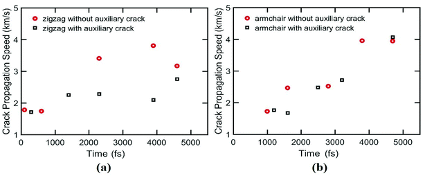
Again, the crack propagation speed of other 2D materials such as graphene,49 hexagonal boron nitride50 and MoS2 (ref. 51) have been investigated previously. But in case of silicene, to the best of our knowledge, no such study is done.
In this study, for the first time, a practically feasible way is presented to increase the ultimate stress of silicene nanosheet containing a main central crack by symmetrically placing auxiliary cracks around the crack tip. The enhancement of the ultimate stress is demonstrated by applying uniaxial load on silicene using MD simulation. In this work, we placed the auxiliary cracks in different positions and we found that these cracks can shield or amply the crack propagation in silicene nanosheet. The effects of temperature on the sheet containing auxiliary cracks are studied. The crack propagation speed of silicene and the effect of auxiliary crack on this speed is investigated. The size effects of auxiliary cracks are also studied for both armchair and zigzag loading condition. Finally, we analyzed the failure resisting and crack arresting phenomena for both armchair and zigzag loading conditions which provides new insights on the possibilities of strain engineering of silicene as well as adopting unique ways to improve the mechanical properties of silicene nanosheet which may lead to a better fabrication process of silicene based nanodevices.
2. Methodology
At first, a 300 Å × 300 Å nanosheet is constructed for uniaxial tensile test simulation. Then cracks of different lengths (approximately 10 Å, 20 Å, 30 Å, 40 Å and 50 Å) are introduced either along armchair or zigzag direction of the nanosheet to investigate the effects of crack length on fracture strength of silicene. The cracks are created by deleting a few rows of atoms. Similar approach for creating initial cracks has been employed in previous studies.30,36,47,48 The size of nanosheet is taken such a way that the sample size effect remains insignificant while keeping computational time within reasonable limit. Note that, the crack lengths are chosen such that the length and width of the nanosheet are at least ten times larger than half crack length in order to avoid the effects of finite dimension.52,53In order to investigate the interaction between main crack and auxiliary cracks, one main crack at the center and four auxiliary symmetric cracks at different positions (Fig. 1) are introduced in the nanosheet. The size of the auxiliary cracks are kept equal to that of the main crack and they are always oriented perpendicularly to the direction of the main crack. Fig. 1 shows the relative position of auxiliary cracks and the main crack in cartesian and polar co-ordinate system. Because of the symmetry, only the co-ordinates of the auxiliary crack positioned in the first quadrant is used to define the positions of all the auxiliary cracks as shown in Fig. 1. To describe the atomistic phenomenon of fracture and investigate the mechanical properties, molecular dynamics simulations are used extensively for silicene.28,30,33,36,54–61 All the simulations are performed in LAMMPS62 software package where periodic boundary conditions were incorporated along the in plane directions (x and y) of the sheet. In order to eliminate the effects of free edges,63 the size of the simulation box was taken as an exact multiple of a unit cell in both directions. The systems were first relaxed using conjugate gradient (CG) minimization scheme. Then NVE ensemble was used to equilibrate the systems which was followed by isothermal-isobaric (NPT) simulations at 300 K temperature and atmospheric pressure. Next, a constant strain rate of 109 s−1 is applied along the y direction which is relatively higher compared to the practical cases. However, such a high strain rate—allows to perform simulations with a reasonable computational resource—have been commonly used in atomistic scale simulations to investigate the material failure phenomena.30,36,64 Atomic stresses under deformation is described by the following equation65
 | (1) |
![[u with combining dot above]](https://www.rsc.org/images/entities/i_char_0075_0307.gif) i is the time derivative of the displacement, rij denotes the position vector and fij denotes the interatomic force applied on atom i by atom j. The thickness of the silicene nanosheet is taken as 3.13 Å.
i is the time derivative of the displacement, rij denotes the position vector and fij denotes the interatomic force applied on atom i by atom j. The thickness of the silicene nanosheet is taken as 3.13 Å.
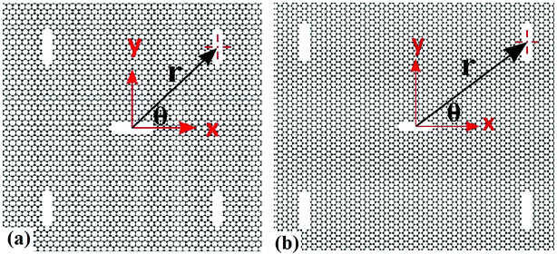 | ||
| Fig. 1 Silicene nanosheets containing four auxiliary cracks and one main crack in (a) zigzag, (b) armchair direction. Uniaxial tension is applied along perpendicular direction to the main crack. | ||
In order to describe the interactions between silicon atoms in the nanosheet, an optimized Stillinger–Weber (SW)66 potential is used. This potential is incorporated because of its successful use in describing thermal67 and mechanical properties30,36 of silicene previously. Furthermore, the obtained buckling height (0.44 Å) after relaxation is in good agreement with DFT calculations.68 The SW potential consists of a two body term and a three body term describing the bond stretching and bond breaking interactions respectively. The mathematical expressions of these interactions are described below-
 | (2) |
 | (3) |
 | (4) |
In order to validate the current method, the fracture strength of a 300 Å × 300 Å silicene nanosheet has been compared with the literature.30 Uniaxial tension is applied in either armchair or zigzag direction at 100 K temperature. The comparison between the values are shown in Table 1. The close proximity of the values obtained by our simulation method and existing literature verifies our method and adopted potential to describe the interactions in silicene nanosheet.
| Ultimate Stress (GPa) | Ultimate Strain (%) | |||
|---|---|---|---|---|
| Direction | Armchair | Zigzag | Armchair | Zigzag |
| Present study | 28.5 | 30.8 | 27.1 | 31 |
| Ref. 30 | 27.8 | 30.6 | 27 | 31 |
3. Results and discussions
3.1 Stress–strain relationships for pre-cracked silicene
We investigate the effects of central crack length on the ultimate stress of silicene nanosheet. Fig. 2 describes the effect of crack length on the ultimate stress of silicene nanosheet containing a central crack. It is evident from the figure that higher crack length reduces the ultimate stress and material failure occurs at relatively lower strain values for both armchair and zigzag loading conditions. This phenomena is quite expected as higher crack length induces more localized stress around the crack tip.69,70 We observe that, for the same crack lengths, the armchair loading direction fails at lower ultimate strains compared to the zigzag loading direction. This phenomenon is observed and explained in previous studies.28,30 In the case of armchair loading direction, one third of the total bonds are parallel to the loading direction. So, the local bond strain in silicon atoms is proportional to the global strain and failure occurs at such global strain when the stretched bond length exceeds the value of critical bond length. However, in case of zigzag loading direction, the bonds are at either 30° or 90° angle with the loading direction. Hence, to reach the critical bond length, much larger stretching of the bond is needed resulting in much higher global strain. So, properties are slightly better when the silicene nanosheet is loaded in zigzag direction.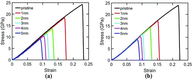 | ||
| Fig. 2 Stress–strain relationships for silicene nanosheet containing a central crack of different lengths. Uniaxial tensile load is applied in (a) zigzag direction, (b) armchair direction. | ||
3.2 The effects of auxiliary cracks
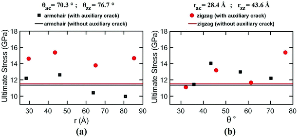 | ||
| Fig. 3 Variation of ultimate stress in the cracked silicene nanosheet with (a) distance (r) and (b) angle (θ) of the auxiliary crack. | ||
Interestingly, for zigzag loading condition, the shielding effects are very prominent due to a unique bond rotation phenomenon at the crack tip leading to the formation of a SW defect at the tip and thus reducing the tip stress (see ESI Video.† The rotation of bond is indicated by the red atoms). This type of atomic fracture process involving the formation of SW defect have also been observed earlier for graphene71 and silicon.72 This unique phenomenon does not occur without the presence of auxiliary cracks. However, the rotation of the bond is facilitated if the atomic movements at the tips are directed towards the loading direction73 which only happens in case of zigzag loading.
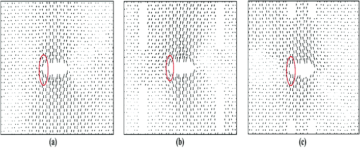
Fig. 4 depicts the displacements of the atoms near the crack tips for different positions of auxiliary cracks from their initial unstressed condition at about 9% strain. Because of the presence of the auxiliary cracks, the atomic movements change as shown in Fig. 4(b) and (c). For θ = 76.7° and r = 43.6 Å, atomic movements are parallel (Fig. 4(c)) to the loading direction facilitating the bond rotation process.
Furthermore, the SW defect formation is found to be independent of the value of r. For this reason, for θ = 76.7°, SW defect is formed near the tip irrespective of r which increases the ultimate stress (Fig. 3(a)). The slight variations of the ultimate stresses in Fig. 3(a) are due to the time of evolution of the defect. If the defect is formed at a lower strain, the ultimate stress is higher and vice versa. On the contrary, the SW defect formation is highly dependent on the angular position of the auxiliary cracks. Fig. 3(b) illustrates the dependency of the ultimate stress on the variation of angular position of the auxiliary cracks. For θ = 32.2° and θ = 61.3°, the pattern of the atomic movements are at an angle to the direction of loading (Fig. 4(b)) which impedes the rotation of the bond at the crack tip and ultimate stress becomes lower. This mechanism is further explained in Section 3.3.2.
For armchair loading direction, ultimate stress is the lowest for the lowest crack length. Because at a particular position, the lower the crack length, the higher the distance between the tips of main crack and auxiliary crack. Thus, the unstressed zone ahead of the auxiliary crack tip remains smaller and cannot provide enough shielding for the main crack and failure initiates from the crack tip (Fig. 4(c)). However, if the auxiliary crack length gets too large, plastic deformations becomes more pronounced ahead of the central crack tip and failure initiates ahead of the crack tip rather than at the tip because of the high plasticity (Fig. 5(b)).
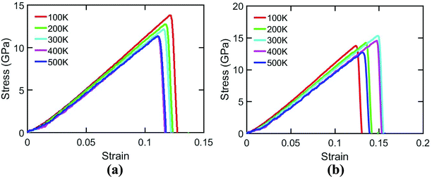 | ||
| Fig. 7 Variation of fracture strength of silicene nanosheet containing auxiliary cracks with the variation of temperature and loaded in (a) armchair, (b) zigzag direction. | ||
In case of zigzag loading condition, MD simulation results shows interesting phenomena. It is clear from the figure that fracture strength increases with temperature upto 300 K temperature and then decreases. This is due to the crack shielding mechanism of silicene nanosheet. The crack propagation at 300 K temperature is mainly suppressed by the rotation of bonds at the crack tips. At this temperature, instead of bond breaking, this bond rotation phenomena occurs due to the energetic and kinetic favorability.71 On the other hand, at lower temperature, the bond rotation phenomenon is not favored due to the lower energy available. Therefore, bond breaking occurs which leads to failure at a lower ultimate stress. However, with the increase of temperature above 300 K, the fracture strength of the sheet decreases again despite of the occurrence of bond rotation process. This is due to the higher atomic movements at these elevated temperatures leading to higher fluctuation in the bond length.59 Therefore, some of the bond lengths exceed the critical bond length and material failure occurs at a lower ultimate stress and strain.
3.3 Crack arresting mechanism
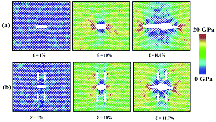
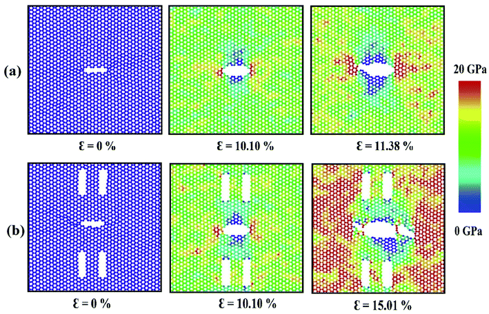
To elucidate the reason behind the increment of the ultimate stress of the sheet, the comparative stress distribution of the silicene nanosheet with and without auxiliary cracks are shown in Fig. 9 at different strains. As the instantaneous stress of an atom fluctuates very rapidly,65 time averaging is needed to gain the stress distribution of the nanosheet at any instant.47,48 To illustrate the stress distribution at a particular instant, we averaged the stresses of every atom for the last 100 timesteps to show the stress distribution. Fig. 9(a) shows the failure mechanism of the silicene nanosheet containing a 30 Å central crack. From the figure, one can see that stress accumulation near the crack is the primary reason of failure for pre-cracked silicene nanosheet. At about 10% strain, the stress of the crack tip begins to exceed the maximum stress needed to break the Si–Si bond which is reported as 25 GPa.30 However, presence of the auxiliary cracks significantly alters the stress distribution around the crack tip due to the interaction between main and auxiliary cracks. The stress accumulation is also higher without auxiliary cracks than that with auxiliary cracks. Although the configuration of the main crack is kept same for both the cases, plastic deformation is more prominent in the latter case at higher strain due to the presence of the auxiliary cracks at such close proximity with the main crack ultimately leading to a change in the crack configuration. This plastic deformation enlarges the width as well as blunts the tips of the central crack. This type of crack configuration disfavors the higher stress concentration around the tips and failure is restricted until higher strain is applied.
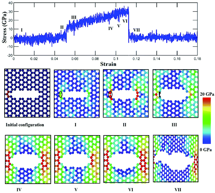
This mechanism can be further explained with the help of Fig. 11 and 12 which show the variation of average atomic stress of the crack tip atoms at the left with the increase of global strain in silicene nanosheet without and with auxiliary cracks. The atomic snapshots around the crack are also shown at different strain levels. Initial atomic structure at the crack tip changes after relaxation by the formation of a weak bond adjacent to the tip as shown in Fig. 11(I). For this reason, the tip atoms do not get stressed at this stage until the breaking of this weak bond as shown in Fig. 11(I) and (II). Sudden jump of the tip stress is observed at about 5% strain which corresponds to the breaking of the weak bond (Fig. 11(III)). The tip stress increases with the increase of global strain and finally failure initiates by the crack propagation as shown in Fig. 11(IV)–(VII).
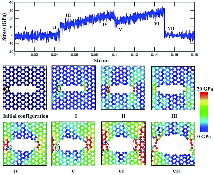
In Fig. 12, it is observed that a weak bond near the tip is formed and atomic stress increase with a sudden jump because of the rupture of the weak bond with the applied strain in a similar way as in the case without auxiliary crack. At higher strain, the bond rotation occurs near the tip which reduces the stress of the tip atoms as shown in Fig. 12(V). Similar occurrences are observed for right crack tip as well. As a result, comparatively higher strain is required to initiate the failure of the material (Fig. 12(VI)). The reason of this bond rotation is behind the alteration of the pattern of the atomic movements. Atomic movements becomes parallel to the loading direction when the strain exceeds about 5%. This type of displacement of atoms has the ability to sustain both bond rotation and bond stretching process.73 Previously, it is reported that two competing process of fracture, either bond rotation or bond breaking at the tip, can occur during the fracture process depending on the energetic and kinetic favorability.71 It is also reported for graphene nanosheet and nanotube that the formation of defect is more energetically favorable at higher strain as this configuration can reduce tensile strain due to the ability of heptagonal configuration of bonds to be stretched more than hexagonal configuration.77,78 The atomic movements at the crack tip are found to be parallel with the loading direction whereas the movement is at an angle without the presence of auxiliary cracks (Fig. 4). This type of atomic movement accompanied by high strain kinetically and energetically favors the bond rotation process. For this reason, the fracture strength of silicene becomes more enhanced by the presence of auxiliary cracks in case of zigzag loading.
4. Conclusion
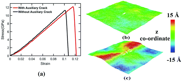
In this research, atomistic simulations have been carried out to investigate the effects of auxiliary cracks on the fracture strength of silicene. It has been observed that the fracture strength of silicene nanosheet in both loading directions increases significantly with the incorporation of auxiliary cracks, and it is more prominent in case of zigzag loading direction than the armchair loading direction. The crack propagation speed and the effects of temperature on the silicene nanosheet containing auxiliary cracks are also studied. The fracture strength shows an interesting increasing–decreasing trend with the increase of temperature. Moreover, in case of zigzag loading direction, for some specific locations of the auxiliary cracks, the atomic movements at the central crack tips have been observed parallel to the loading direction which leads to the occurrence of a bond rotation at the crack tip that in turn increases the fracture strength of the silicene nanosheet significantly. It is also observed that the presence of the auxiliary cracks invokes out of plane deformation of the silicene sheet. Finally, this study sheds light on understanding the failure mechanism of silicene nanosheet more extensively. Also this study opens a new possibility for tailoring the fracture strength of silicene nanosheet. Again the increased resistance to fracture may lead to possible strain engineering of silicene. Alongside the improvement of mechanical properties and possibility of strain engineering, the bond rotation due to the applied strain along zigzag direction might enable the alteration of local electronic properties of silicene nanosheet which may lead to noble applications.Conflicts of interest
There are no conflicts to declare.Acknowledgements
The authors of this paper would like to express their gratitude to the Department of Mechanical Engineering, BUET for providing the computational facilities. They would also like to acknowledge Multiscale Mechanical Modelling and Research Network (MMMRN) group for the technical support to conduct the research.References
- X. Gu and R. Yang, arXiv preprint arXiv:1509.07762.
- B. Zhu, X. Chen and X. Cui, Sci. Rep., 2015, 5, 9218 CrossRef PubMed.
- H.-P. Komsa and A. V. Krasheninnikov, Phys. Rev. B, 2012, 86, 241201 CrossRef.
- M. M. Ugeda, A. J. Bradley, S.-F. Shi, F. H. da Jornada, Y. Zhang, D. Y. Qiu, W. Ruan, S.-K. Mo, Z. Hussain, Z.-X. Shen, F. Wang, S. G. Louie and M. F. Crommie, Nat. Mater., 2014, 13, 1091–1095 CrossRef PubMed.
- T. Borzda, C. Gadermaier, N. Vujicic, P. Topolovsek, M. Borovsak, T. Mertelj, D. Viola, C. Manzoni, E. A. A. Pogna, D. Brida, M. R. Antognazza, F. Scotognella, G. Lanzani, G. Cerullo and D. Mihailovic, arXiv:1412.5338 [cond-mat].
- A. K. Geim and K. S. Novoselov, Nat. Mater., 2007, 6, 183–191 CrossRef PubMed.
- D. Akinwande, C. J. Brennan, J. S. Bunch, P. Egberts, J. R. Felts, H. Gao, R. Huang, J.-S. Kim, T. Li, Y. Li, K. M. Liechti, N. Lu, H. S. Park, E. J. Reed, P. Wang, B. I. Yakobson, T. Zhang, Y.-W. Zhang, Y. Zhou and Y. Zhu, Extreme Mech. Lett., 2017, 13, 42–77 CrossRef.
- J. A. Jackman, N.-J. Cho, M. Nishikawa, G. Yoshikawa, T. Mori, L. K. Shrestha and K. Ariga, Chem.–Asian J., 2018 Search PubMed , just accepted.
- A. Gupta, T. Sakthivel and S. Seal, Prog. Mater. Sci., 2015, 73, 44–126 CrossRef.
- G. R. Bhimanapati, Z. Lin, V. Meunier, Y. Jung, J. Cha, S. Das, D. Xiao, Y. Son, M. S. Strano, V. R. Cooper, L. Liang, S. G. Louie, E. Ringe, W. Zhou, S. S. Kim, R. R. Naik, B. G. Sumpter, H. Terrones, F. Xia, Y. Wang, J. Zhu, D. Akinwande, N. Alem, J. A. Schuller, R. E. Schaak, M. Terrones and J. A. Robinson, ACS Nano, 2015, 9, 11509–11539 CrossRef PubMed.
- S. Z. Butler, S. M. Hollen, L. Cao, Y. Cui, J. A. Gupta, H. R. Gutiérrez, T. F. Heinz, S. S. Hong, J. Huang, A. F. Ismach, E. Johnston-Halperin, M. Kuno, V. V. Plashnitsa, R. D. Robinson, R. S. Ruoff, S. Salahuddin, J. Shan, L. Shi, M. G. Spencer, M. Terrones, W. Windl and J. E. Goldberger, ACS Nano, 2013, 7, 2898–2926 CrossRef PubMed.
- Y. Han, Y. Ge, Y. Chao, C. Wang and G. G. Wallace, J. Energy Chem., 2018, 27, 57–72 CrossRef.
- A. H. Khan, S. Ghosh, B. Pradhan, A. Dalui, L. K. Shrestha, S. Acharya and K. Ariga, Bull. Chem. Soc. Jpn., 2017, 90, 627–648 CrossRef.
- B. Anasori, M. R. Lukatskaya and Y. Gogotsi, Nat. Rev. Mater., 2017, 2, 16098 CrossRef.
- A. H. Castro Neto, F. Guinea, N. M. R. Peres, K. S. Novoselov and A. K. Geim, Rev. Mod. Phys., 2009, 81, 109–162 CrossRef.
- P. Vogt, P. De Padova, C. Quaresima, J. Avila, E. Frantzeskakis, M. C. Asensio, A. Resta, B. Ealet and G. Le Lay, Phys. Rev. Lett., 2012, 108, 155501 CrossRef PubMed.
- P. De Padova, C. Quaresima, C. Ottaviani, P. M. Sheverdyaeva, P. Moras, C. Carbone, D. Topwal, B. Olivieri, A. Kara, H. Oughaddou, B. Aufray and G. Le Lay, Appl. Phys. Lett., 2010, 96, 261905 CrossRef.
- K. Takeda and K. Shiraishi, Phys. Rev. B, 1994, 50, 14916–14922 CrossRef.
- G. G. Guzmán-Verri and L. C. Lew Yan Voon, Phys. Rev. B, 2007, 76, 075131 CrossRef.
- S. Cahangirov, M. Topsakal, E. Aktürk, H. Şahin and S. Ciraci, Phys. Rev. Lett., 2009, 102, 236804 CrossRef PubMed.
- C.-L. Lin, R. Arafune, K. Kawahara, M. Kanno, N. Tsukahara, E. Minamitani, Y. Kim, M. Kawai and N. Takagi, Phys. Rev. Lett., 2013, 110, 076801 CrossRef PubMed.
- M. Rachid Tchalala, H. Enriquez, A. J. Mayne, A. Kara, S. Roth, M. G. Silly, A. Bendounan, F. Sirotti, T. Greber, B. Aufray, G. Dujardin, M. Ait Ali and H. Oughaddou, Appl. Phys. Lett., 2013, 102, 083107 CrossRef.
- W. Zhang, L. Sun, J. M. V. Nsanzimana and X. Wang, Adv. Mater., 2018, 30(15), 1705523 CrossRef PubMed.
- P. De Padova, H. Feng, J. Zhuang, Z. Li, A. Generosi, B. Paci, C. Ottaviani, C. Quaresima, B. Olivieri, M. Krawiec and Y. Du, J. Phys. Chem. C, 2017, 121, 27182–27190 CrossRef.
- A. Fleurence, R. Friedlein, T. Ozaki, H. Kawai, Y. Wang and Y. Yamada-Takamura, Phys. Rev. Lett., 2012, 108, 245501 CrossRef PubMed.
- T. H. Osborn and A. A. Farajian, J. Phys. Chem. C, 2012, 116, 22916–22920 CrossRef.
- R. Qin, C.-H. Wang, W. Zhu and Y. Zhang, AIP Adv., 2012, 2, 022159 CrossRef.
- T. Botari, E. Perim, P. a. S. Autreto, A. C. T. van Duin, R. Paupitz and D. S. Galvao, Phys. Chem. Chem. Phys., 2014, 16, 19417–19423 RSC.
- X. Yuan, G. Lin and Y. Wang, Mol. Simul., 2016, 42, 1157–1164 CrossRef.
- T. Rakib, S. Mojumder, S. Das, S. Saha and M. Motalab, Phys. B, 2017, 515, 67–74 CrossRef.
- B. Feng, Z. Ding, S. Meng, Y. Yao, X. He, P. Cheng, L. Chen and K. Wu, Nano Lett., 2012, 12, 3507–3511 CrossRef PubMed.
- H. Jamgotchian, B. Ealet, Y. Colignon, H. Maradj, J.-Y. Hoarau, J.-P. Biberian and B. Aufray, J. Phys.: Condens. Matter, 2015, 27, 395002 CrossRef PubMed.
- N. Ding, H. Wang, X. Chen and C.-M. L. Wu, RSC Adv., 2017, 7, 10306–10315 RSC.
- S. M. Nahid, F. H. Bhuiyan, T. Rakib and S. Mojumder, Effects of Defects on the Fracture Strength of Hexagonal Boron Nitride, unpublished Search PubMed.
- T. Zhang, X. Li and H. Gao, Int. J. Fract., 2015, 196, 1–31 CrossRef.
- T. Rakib, S. Saha, M. Motalab, S. Mojumder and M. M. Islam, Sci. Rep., 2017, 7, 14629 CrossRef PubMed.
- T. Zhang, X. Li and H. Gao, J. Mech. Phys. Solids, 2014, 67, 2–13 CrossRef.
- T. Zhang, X. Li and H. Gao, Extreme Mech. Lett., 2014, 1, 3–8 CrossRef.
- F. Meng, C. Chen and J. Song, J. Phys. Chem. Lett., 2015, 6, 4038–4042 CrossRef PubMed.
- G. Rajasekaran and A. Parashar, Diamond & Related Materials, 2017, Complete, pp. 90–99 Search PubMed.
- E. Sandoz-Rosado, T. D. Beaudet, R. Balu and E. D. Wetzel, Nanoscale, 2016, 8, 10947–10955 RSC.
- X. Yang and J. Ni, Phys. Rev. B, 2005, 72, 195426 CrossRef.
- J.-Y. Chung, V. Sorkin, Q.-X. Pei, C.-H. Chiu and Y.-W. Zhang, J. Phys. D: Appl. Phys., 2017, 50, 345302 CrossRef.
- S. X. Gong and S. A. Meguid, Int. J. Mech. Sci., 1992, 34, 933–945 CrossRef.
- K. X. Hu, A. Chandra and Y. Huang, Int. J. Solids Struct., 1993, 30, 1473–1489 CrossRef.
- T. Liu and S. Groh, Mater. Sci. Eng., 2014, 609, 255–265 CrossRef.
- M. A. N. Dewapriya and S. A. Meguid, Carbon, 2017, 125, 113–131 CrossRef.
- M. A. N. Dewapriya and S. A. Meguid, Comput. Mater. Sci., 2018, 141, 114–121 CrossRef.
- P. R. Budarapu, B. Javvaji, V. K. Sutrakar, D. Roy Mahapatra, G. Zi and T. Rabczuk, J. Appl. Phys., 2015, 118, 064307 CrossRef.
- R. Abadi, R. P. Uma, M. Izadifar and T. Rabczuk, Comput. Mater. Sci., 2017, 131, 86–99 CrossRef.
- H. Bao, Y. Huang, Z. Yang, Y. Sun, Y. Bai, Y. Miao, P. K. Chu, K. Xu and F. Ma, J. Phys. Chem. C, 2018, 122, 1351–1360 CrossRef.
- A. Mattoni, L. Colombo and F. Cleri, Phys. Rev. Lett., 2005, 95, 115501 CrossRef PubMed.
- C. Fabrizio, R. Phillpot Simon, W. Dieter and Y. Sidney, J. Am. Ceram. Soc., 2005, 81, 501–516 CrossRef.
- S. Rouhi, Comput. Mater. Sci., 2017, 131, 275–285 CrossRef.
- R. E. Roman and S. W. Cranford, Comput. Mater. Sci., 2014, 82, 50–55 CrossRef.
- A. İnce and Ş. Erkoç, Phys. Status Solidi B, 2012, 249, 74–81 CrossRef.
- Y. Jing, Y. Sun, H. Niu and J. Shen, Phys. Status Solidi B, 2013, 250, 1505–1509 CrossRef.
- R. Ansari, S. Rouhi and S. Ajori, Superlattices Microstruct., 2014, 65, 64–70 CrossRef.
- Q.-X. Pei, Z.-D. Sha, Y.-Y. Zhang and Y.-W. Zhang, J. Appl. Phys., 2014, 115, 023519 CrossRef.
- M. R. Chávez-Castillo, M. A. Rodríguez-Meza and L. Meza-Montes, RSC Adv., 2015, 5, 96052–96061 RSC.
- M.-Q. Le and D.-T. Nguyen, Appl. Phys. A, 2015, 118, 1437–1445 CrossRef.
- S. Plimpton, J. Comput. Phys., 1995, 117, 1–19 CrossRef.
- M. A. N. Dewapriya, A. S. Phani and R. K. N. D. Rajapakse, Modell. Simul. Mater. Sci. Eng., 2013, 21, 065017 CrossRef.
- T. H. Pial, T. Rakib, S. Mojumder, M. Motalab and M. A. S. Akanda, Phys. Chem. Chem. Phys., 2018, 20, 8647–8657 RSC.
- D. H. Tsai, J. Chem. Phys., 1979, 70, 1375–1382 CrossRef.
- F. H. Stillinger and T. A. Weber, Phys. Rev. B, 1985, 31, 5262–5271 CrossRef.
- X. Zhang, H. Xie, M. Hu, H. Bao, S. Yue, G. Qin and G. Su, Phys. Rev. B, 2014, 89, 054310 CrossRef.
- Q. Peng, X. Wen and S. De, RSC Adv., 2013, 3, 13772–13781 RSC.
- T. L. Anderson, Fracture Mechanics: Fundamentals and Applications, CRC Press, 4th edn, 2017 Search PubMed.
- G. Pluvinage and L. Milovic, Fracture at all Scales, Springer International Publishing, 2017 Search PubMed.
- S. S. Terdalkar, S. Huang, H. Yuan, J. J. Rencis, T. Zhu and S. Zhang, Chem. Phys. Lett., 2010, 494, 218–222 CrossRef.
- S. Huang, S. Zhang, T. Belytschko, S. S. Terdalkar and T. Zhu, J. Mech. Phys. Solids, 2009, 57, 840–850 CrossRef.
- F. Liu, P. Ming and J. Li, Phys. Rev. B, 2007, 76, 064120 CrossRef.
- M. A. N. Dewapriya, R. Rajapakse and A. S. Phani, in ICF13, 2013 Search PubMed.
- V. B. Shenoy, C. D. Reddy, A. Ramasubramaniam and Y. W. Zhang, Phys. Rev. Lett., 2008, 101, 245501 CrossRef PubMed.
- Q. Lu and R. Huang, Phys. Rev. B, 2010, 81, 155410 CrossRef.
- J. da Silva-Araújo, A. J. M. Nascimento, H. Chacham and R. W. Nunes, Nanotechnology, 2013, 24, 035708 CrossRef PubMed.
- M. Buongiorno Nardelli, B. I. Yakobson and J. Bernholc, Phys. Rev. B, 1998, 57, R4277–R4280 CrossRef.
Footnote |
| † Electronic supplementary information (ESI) available. See DOI: 10.1039/c8ra04728f |
| This journal is © The Royal Society of Chemistry 2018 |

