
 Open Access Article
 This Open Access Article is licensed under a
 Creative Commons Attribution 3.0 Unported Licence
Template conversion of MoO3 to MoS2 nanoribbons: synthesis and electrochemical properties†
Luciana Vieira‡
*a,
Jose de Ribamar Martins Netob,
Odair Pastor Ferreirac,
Roberto Manuel Torresib,
Susana Ines Cordoba de Torresi b and
Oswaldo Luiz Alves*a
b and
Oswaldo Luiz Alves*a
aLaboratory of Solid State Chemistry (LQES), Institute of Chemistry, University of Campinas (UNICAMP), Campinas, São Paulo, Brazil. E-mail: luciana.vieira@igb.fraunhofer.de; oalves@iqm.unicamp.br
bDept. Química Fundamental, Instituto de Química, Universidade de São Paulo, São Paulo, Brazil
cLaboratório de Materiais Funcionais Avançados (LaMFA), Departamento de Física, Universidade Federal do Ceará, Fortaleza, Brazil
First published on 28th August 2018
Abstract
Hydrothermally synthesized α-MoO3 nanoribbons were converted to MoS2 whilst retaining the same morphology by a solid–gas reaction at 800 °C in a H2S/H2/N2 atmosphere. In order to keep the nanoribbon morphology from the oxide in the sulfide, it was crucial to have a H2S stream during the whole heating process. Thereby, the first layer of sulfide is formed as soon as the oxide is activated avoiding coalescence of the nanoribbons. Afterwards, the sulfidization takes place from the outer shell to the inner core of the nanoparticles. Both α-MoO3 and MoS2-NR were investigated for the electrochemical intercalation of lithium-ions. The electrochemical insertion and removal of lithium in the molybdenum oxide are accompanied by a change of color, which was measured by in situ UV-Vis. Spectroelectrochemical experiments showed a distinguished electrochromic behavior with a significant potential-dependent change in absorbance at 660 nm upon Li+ insertion. Analysis of in situ voltammetry revealed the presence of three active sites for lithium insertion in the MoO3-NRs, which are accompanied by only two chromophores in the same potential range. Voltammetric measurements of the MoS2 nanoribbons presented a reversible reduction of MoS2 to LixMoS2, followed by Mo and Li2S, which can be further reduced to Li and S at more negative potentials. Such sulfide materials are highly promising for lithium batteries. This template synthesis is a simple method to obtain high purity MoS2 nanoparticles with a controlled morphology of nanoribbons.
1 Introduction
Materials with the capacity of simultaneously changing the electrical and optical properties upon insertion or removal of ions are known as electrochromic materials. These materials have promising applications such as electrochromic windows, lithium-ion batteries, catalysis and sensors.1–4For instance, tungsten oxides have been widely investigated for their electrochromic properties.1 Likewise, molybdenum oxides also show pronounced electrochemical5 and electrochromic properties.1 Orthorhombic α-MoO3, for example, consists of a layered structure of covalently bonded MoO6 octahedra connected at the edges and corners forming channels,6 which allow the intercalation of ions to form molybdenum bronzes MxMoO3 (M = H+, Li+, Na+, K+, Mg2+).6 This ion insertion in the α-MoO3 channels is accompanied by a change in coloration from pale to dark-blue.7 Nanostructured α-MoO3 with morphologies such as nanoparticles8 and nanorods9–11 are expected to have an improved electrochromic response due to their smaller diffusion path3 and increased surface area.5
Molybdenum sulfides have been noted for their superior performance for energy storage applications such as lithium-ion batteries (LIB).12–14 Different nanostructures including nanorods15 and single layered MoS2 (ref. 16) have been investigated with respect to their electrochemical properties. Therefore, several attempts of preparing uniform MoO3 nanorods as precursors for MoS2 with the same morphology have been reported.15,17–23
One of the methods to prepare nanostructured MoS2 is the solid–gas reaction of bulk α-MoO3 in an H2S/H2/N2 atmosphere at 800 °C.24 The oxide nanoparticles are formed in situ in the gas phase and the oxide-to-sulfide reaction takes place from the outer layer to the inner core of the oxide nanoparticles.25 Consequently, the size and shape of the oxide normally determine the morphology of the final sulfide materials.25–28 Hence, oxide nanorods usually generate sulfide nanotubes (NT) whereas spherical nanoparticles generate inorganic fullerene-like (IF) MoS2.28 Nevertheless, because the preparation of the molybdenum oxide nanoparticle takes place in the gas-phase at 800 °C,25 it is rather challenging to control the morphology of the oxide and consequently, that of the sulfide.24 Thus, for most of the solid–gas preparation methods described so far, a mixture of nanotubes and spherical fullerene-like MoS2 nanoparticles is obtained.28
Alternatively, several attempts of preparing uniform MoO3 nanorods as precursors for MoS2 with the same morphology have been reported.15,17–23 Hydrothermal treatment of sodium molybdate15,17,18 or acidified ammonium heptamolybdate22,23 led to uniform MoO3 nanorods. Thermolysis of ammonium molybdate generated a mixture of spherical and rod-shaped MoO3.21 These oxide nanoparticles were converted to MoS2 using H2 as a reducing agent and H2S19–23 or S15,17 as the sulfur source. However, many of the attempts of sulfidizing MoO3 nanorods was not successful for the homogeneity of the final product, resulting in mixtures of MoS2 nanotubes and fullerene-like nanoparticles,21 mixtures of MoS2 nanorods with nanoparticles,19 MoS2 nanorods with an oxide core due to incomplete sulfidization23 and in certain cases the sufidization led to a complete loss of the original oxide morphology.19,20,29
In this work, we contribute to the development of novel synthetic methods for the preparation of MoS2 with a high morphological yield of nanoribbons. α-MoO3-NR synthesized by a hydrothermal method was used as the precursor for the synthesis of MoS2-NR at 800 °C under a stream of H2S and H2/N2 since the beginning of the heating ramp. With this strategy, we were able to retain the oxide nanoribbon morphology in the sulfide product. A mechanism for the oxide-to-sulfide conversion has been proposed. We investigated the electrochemical behavior toward lithium insertion and removal of both oxide and sulfide nanostructures and we show that the MoO3 nanoribbons have a pronounced electrochromic behavior, whereas MoS2 present a reversible electrochemical behavior, making the oxide and sulfide good candidates for electrochromic devices and LIBs, respectively.
2 Experimental
2.1 Preparation of MoO3 nanoribbons
MoO3 nanoribbons were prepared by a previously described hydrothermal method.30 In a typical procedure, 310 mg of previously prepared molybdic acid31 was added to 0.7 mL of glacial acetic acid (Chemco, 99.7%) and 1.8 mL of deionized water in a 45 mL capacity Teflon-sealed stainless steel autoclave. Hydrothermal treatment was performed at 180 °C for 7 days. After cooling to room temperature, the product was filtered and washed stepwise with water, ethanol and ether. The pale-blue powder obtained was vacuum dried with a final yield of 93%.2.2 Preparation of MoS2 nanoribbons
The prepared MoO3 nanoribbons were dispersed carefully in a boat quartz plate and subsequently placed in a tubular furnace. After purging with N2 (100 mL min−1), the gas stream was replaced by 5/95% H2/N2 (96 mL min−1) and 99.9% H2S (6 mL min−1). Subsequently, the quartz tube was heated to 800 °C with a heating ramp of 30 °C min−1 and kept at the final temperature for 30 min. After cooling to room temperature, a dark powder of MoS2 was removed from the oven.2.3 Electrochemical characterization
Glasses covered with a conductive coating of indium-tin oxide (ITO, Delta Technologies, sheet resistance 15–25 Ω sq−1) with dimensions of 7 × 50 × 0.7 mm were used as substrates for electrochemical measurements. A dispersion of the MoO3 nanoribbons was prepared by sonicating 1 mg of MoO3 in 1 mL of methanol for 10 min. Thin films of the oxide were prepared by drop-casting this dispersion onto the substrates. A platinum sheet and silver wire were used as counter and quasi-reference electrode, respectively. The electrolyte was 1 mol L−1 LiClO4 in propylene carbonate (PC).Electrochemical measurements were carried out using an autolab PGSTAT 30 potentiostat/galvanostat (Eco Chemie). Simultaneous transmittance measurements were recorded at 660 nm using a solid-state light source (World Precision Instruments). The light passed through an electrochemical cell and was transported with optical fibers to a photodiode amplifier PDA1 (World Precision Instruments), linked to the ADC port in the potentiostat. UV-Vis spectra at different applied potentials were registered with an HP8453 Spectrophotometer.
The dispersion of MoS2 was prepared by sonicating 1 mg of MoS2 in 1 mL of acetonitrile. Thin films were also prepared onto ITO by drop-casting. Electrochemical measurements of the MoS2 film were carried out in an argon-filled glove box hooked up to an autolab PGSTAT 30 (Eco Chemie). Lithium sheets were used as the reference and counter electrode in an electrolyte of 1 mol L−1 bis(trifluoromethane)-sulfonimide lithium (LiTFSI) in PC.
2.4 Nanoparticles characterization
X-ray powder diffraction (XRD) patterns were obtained using a Shimadzu XRD7000 diffractometer, operating with CuKα radiation, at 30 mA and 40 kV and a 1° min−1 scan rate. Scanning electron microscope (SEM) images were obtained using a JEOL 6360LV instrument and transmission electron microscope (TEM) images were obtained using a Carl Zeiss CEM-902. Thermogravimety and differential thermal analysis (TG and DTA) were carried out using a TA equipment, model SDTQ600. Fourier transform infrared (FTIR) spectroscopy of the sample prepared as KBr wafers were recorded on a Bomen FTLA 2000 spectrophotometer. Each spectrum was measured with a total of 32 scans and a resolution of 4 cm−1. Raman spectra were recorded at an ambient temperature on a Renishaw system 3000 Raman imaging microscope (ca. 1 μm spatial resolution) using a He–Ne laser (1.96 eV) with a 632.8 nm excitation line. The laser power density was optimized in order to avoid overheating of the nanoparticle samples by the laser beam.3 Results and discussion
3.1 Synthesis of molybdenum oxide and sulfide nanoribbons
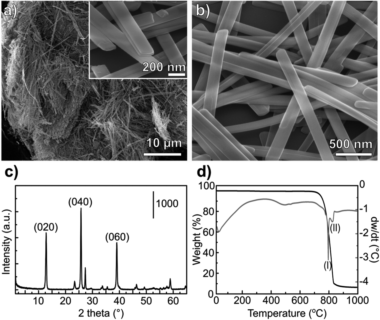 | ||
| Fig. 1 Morphological and physicochemical characterization of the α-MoO3-NR. SEM images at different magnifications are shown in (a) and (b). The XRD pattern of the as-synthesized MoO3-NR is shown in (c) and the thermogravimetry, with weight loss (black) and differential weight loss (gray) are shown in (d). | ||
During the hydrothermal synthesis, MoO3 nanostructures precipitate from MoO3·2H2O dissolved in acidic media, without the formation of intermediate phases.34 The complete conversion of MoO3·2H2O to α-MoO3 is supported by the TG and DSC profile (Fig. 1d). The release of adsorbed water occurs until 100 °C and the absence of any signal related to coordinated water – that should appear up to 400 °C (ref. 35) – confirms the formation of the stable orthorhombic structure.
The morphology of the MoO3 nanoribbons is quite sensitive to the annealing temperature. At around 550–600 °C the nanoribbons can collapse forming large plates.36 The DTA curve shows an endothermic wave at around 550 °C (Fig. 1c), which could be correlated with this morphology loss, also visible by Raman spectroscopy.36 The collapsing of the nanoribbons morphology is a critical point for converting the oxides to sulfides while maintaining the morphology. For a successful template sulfidization, a first outer sulfide layer must be formed below 500 °C, as it will be discussed in the following session. Sublimation of the oxide starts after 700 °C, noticed by the abrupt weight loss and the endothermic peak at 795 °C. Almost all of the oxide mass is volatilized at 850 °C.
Both Raman and infrared spectra (Fig. 2) show characteristic stretching modes of the crystalline orthorhombic α-MoO3.36–41 α-MoO3 consists of distorted MoO6 octahedra with the Mo–O bond length varying between 167 and 233 pm.38 The oxygen atoms in the MoO6 octahedra can be divided into three types: (i) terminal Mo–O from unshared oxygen, (ii) Mo2–O edge-shared oxygen in common with two or three octahedra, i.e. bound to two metal atoms and (iii) Mo3–O, an oxygen atom bound to 3 metals.40,41 These three stretching modes are observed in both Raman and IR spectra (Fig. 2) at (i) 996, (ii) 826 and (iii) 667 cm−1;42 and (i) 998, (ii) 868 and (iii) 560 cm−1,40 respectively.
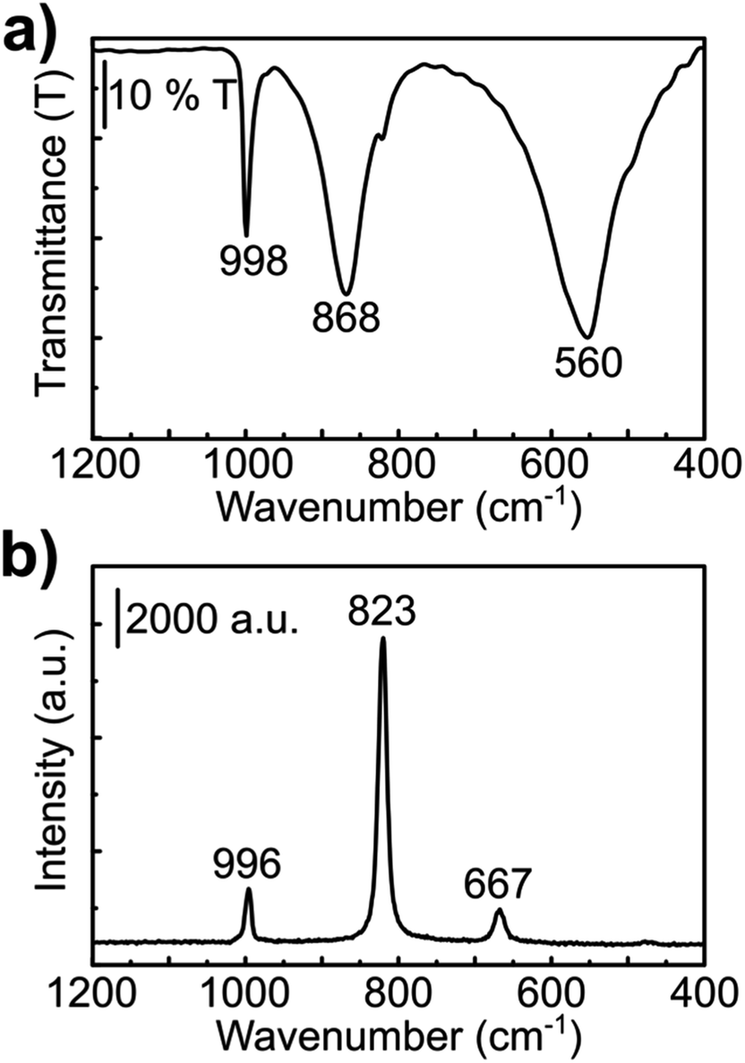 | ||
| Fig. 2 Spectroscopic analyses of the as-synthesized α-MoO3 nanoribbons. (a) FTIR and (b) Raman spectra. | ||
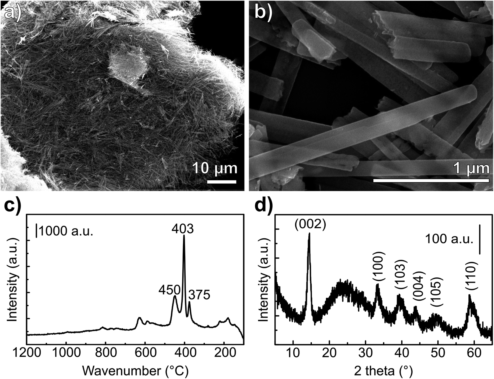 | ||
| Fig. 3 Morphological and physicochemical characterization of the MoS2-NR. (a and b) SEM images, (c) Raman spectrum and (d) XRD pattern. The broad peak at 25° in the XRD pattern is originated from the glass substrate. | ||
Raman spectra of nanoribbons, nanotubes and bulk MoS2 (ref. 43) showed that the nanoribbon Raman bands are shifted downward and more similar to the spectrum of the bulk sulfide when compared to the Raman spectrum of MoS2 nanotubes. The wavenumbers, as well as the band relative intensities for the Raman spectrum of the prepared material (Fig. 3c) are consistent with the spectrum reported for MoS2 nanoribbons.43 The in-plane displacement E12g of Mo–S is observed at 375 cm−1 whereas the out-of-plane A1g has a very intense band at 403 cm−1.44 The weak band at 450 cm−1 corresponds to the second order zone-edge phonon 2LA(M) of MoS2.44,45 Moreover, no bands of MoO2 or MoO3 were observed, consistently with the XRD observations.
The mechanism of sulfidization of MoO3 to MoS2-IF and -NT described in the literature24–27 consists of a gas-phase reaction involving three steps: firstly MoO3 powder is sublimed at 800 °C under N2 atmosphere generating oxide nanoparticles (5–300 nm). Subsequently, the oxide vapor is reduced to MoO3−x under a flow of 5% H2/95% N2 at 820 °C. Finally, the sub-oxide is converted to sulfide upon a stream of H2S at 840 °C, generating MoS2 inorganic fullerenes (IF) and/or nanotubes (NT). According to this mechanism, the size and shape of the original oxide nanoparticle is maintained after the conversion to the sulfide.25,26 Yet, as this method for the preparation of the oxide nanoparticle takes place in the gas-phase, it is rather difficult to control the morphology of the oxide and consequently of the sulfide. Hence, a mixture of IF and NT-MoS2 is obtained.
In this work, we suggest a new synthetic approach for preparing MoS2 with nanoribbon morphology. It involves first preparing the precursor material – molybdenum oxide – already with the desired final morphology of nanoribbons. Then, we provide a sulfur source for the conversion of MoO3 to MoS2 from a stream of H2S, and we thermally treat the material heating from room temperature up to 800 °C. By streaming H2S from the beginning of the heating ramp, the collapsing of the MoO3-NR is successfully avoided and MoS2 with nanoribbons morphology is obtained (Fig. 4). The formation of an outer-shell of MoS2 onto the MoO3-NR is likely to be formed immediately during heating of the oxide and hinders the coalescence – at 500 °C (ref. 36) – and the sublimation of the oxide nanoparticle. Experiments performed with an H2S stream that starts only when the heating treatment reaches 400 °C exhibited loss of nanoribbon morphology (Fig. SI4†), similarly to the results reported elsewhere for sulfidization of MoO3 nanoribbons under H2S.20 Our results suggest that the reaction takes place from the outer shell to the inner core of the nanoparticle. The reaction is limited by the slow diffusion of H2S into the oxide core27 and the nanoribbon morphology of the oxide precursor is well maintained in the final sulfide (Fig. 4). MoS2 nanoparticles obtained have 1D morphology, with 200 nm diameter and up to several μm lengths. The obtained 1D-MoS2 have no oxide or hollow core, different from the reports where nanotubes17,21 or nanorods with an oxide core23 were produced from the sulfidization of molybdenum oxide nanorods.
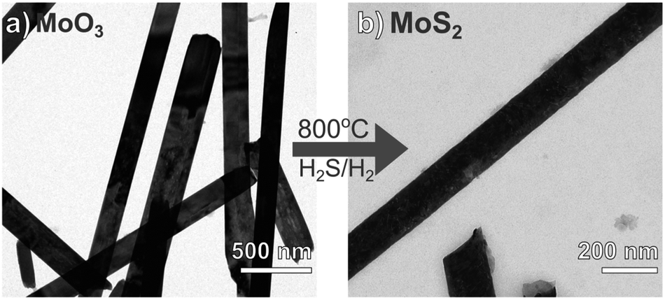 | ||
| Fig. 4 TEM characterization of the synthesized nanoribbons. (a) α-MoO3 and (b) MoS2 generated from sulfidization of the oxide in N2/H2/H2S atmosphere at 800 °C. | ||
3.2 Electrochemical characterization of nanoribbons
Starting at open circuit potential (+0.4 V) with a negative sweep direction, three well-defined reduction peaks are observed at −0.25, −0.37 and −0.65 V vs. Ag/Ag+ (Fig. 5a). These cathodic peaks are characteristics for Li+ intercalation into the molybdenum oxide structure, forming molybdenum bronze (LixMoO3).6 In the anodic scan, de-intercalation of lithium is identified by the oxidation wave at −0.3 V, followed by two small anodic peaks at −0.1 and +0.05 V vs. Ag/Ag+. Multiple reduction peaks in α-MoO3 films are attributed to the insertion of Li+ in distinct energetic sites from the oxide structure.46,47 However, part of the inserted Li+ ions can be trapped into the cavities of the layered structure6 and, consequently, the intercalation/de-intercalation redox reaction is not fully reversible.7 In this case, the current diminishes in the subsequent voltammetric cycles, as observed from the first to the third cycles (Fig. 5a). The coulombic efficiency is also quite low: 85, 70 and 52% from the first to the third voltammetric cycle, respectively. The background CV of an ITO film without MoO3 shows that the electro-decomposition of the PC electrolyte in this potential region is minimal. Thus, the low efficiency should be mostly attributed to the irreversible formation of bronzes such as LixMoIV–VIO3.7 This irreversible intercalation can be even more drastic with ions larger than Li+ such as Mg2+.6 Voltammetric experiments in a PC solution containing MgClO4 (Fig. SI3†) showed that the insertion of Mg2+ is totally irreversible with no anodic peaks at all, due to the entrapment of Mg2+ ions within the oxide interlayer space.6
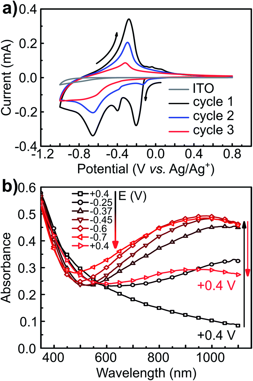 | ||
| Fig. 5 Cyclic voltammetry and potential-dependent UV-Vis of α-MoO3-NR films. (a) Three first CVs at 10 mV s−1 scan rate starting negatively from OCP (+0.4 V) and (b) UV-Vis spectra of a MoO3 film on ITO at different applied potentials. The indicated potential was held for 15 s before each measurement. Electrolytic solution: 1 mol L−1 LiClO4. | ||
The electrochemical insertion of Li+ with the formation of LixMoO3 bronzes (eqn (1)) is accompanied by a change in coloration from pale-blue MoO3 to dark-blue LixMoO3.1 The absorbance change in the visible region was monitored as a function of the applied potential (Fig. 5b). When stepping the potential down, from +0.4 to −0.7 V, a significant increase in absorbance is observed. This absorbance change is corresponding to the change of color in the oxide from pale to dark blue. Moreover, as already pointed out that the electrochemical lithium insertion is not totally reversible, the absorbance change is consistently not completely reversible when stepping back to the initial potential (+0.4 V).
| MoO3 + xLi+ + xe− → LixMoO3 | (1) |
The transmittance change at a single wavelength (660 nm) was monitored simultaneously with cyclic voltammetry (Fig. 4). I/E (Fig. 6a) and A/E (Fig. 6b) potentio-dynamic profiles of a MoO3 film were started at +0.8 V with a negative sweep direction. A remarkable increase in absorption is observed at potentials more negative than −0.1 V (Fig. 6b). Scanning back to positive potentials causes the absorption to decrease, yet not to the starting point. This hysteresis can be correlated with an irreversible lattice expansion during insertion and kinetically slow de-intercalation of lithium during bleaching.7
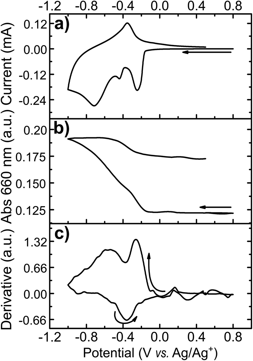 | ||
| Fig. 6 Spectroelectrochemical measurement of α-MoO3-NR films at 660 nm. (a) Cyclic voltammetry at 10 mV s−1, (b) in situ absorbance and (c) differentiate of absorbance in function of potential applied to MoO3 film on ITO in 1 mol L−1 LiClO4. | ||
The differential curve of absorbance versus potential (dA/dt vs. E, Fig. 6c) shows two changes of optical density with potential, which take place simultaneously with two of the three cathodic peaks. The simultaneous coloration and electrochemical change, occurring at the same rate, indicate the presence of two chromogenic species in the molybdenum oxide, which are correlated to the intercalation of Li+ at a different energetic interlayer spacing of the MoO6 octahedron layers.7 As for the oxidation, only one chromogenic process is observed in the differential spectrum, which superposes the main oxidation wave at −0.35 V.
The CV of the MoS2-NR (Fig. 7) starting at +1.2 V with a cathodic scan direction, shows two cathodic peaks rising at +0.7 and +0.3 V. On the anodic scan, two well-defined oxidation peaks are observed at +0.4 and +0.7 V, followed by a broad wave from +1.3 to +2.5 V centered at ca. +1.5 V. The coulombic efficiency of the lithium insertion/de-insertion is 95.5% (whole anodic over cathodic charge), which is considerably higher than that observed for lithium intercalation/de-intercalation in the molybdenum oxide (85%).
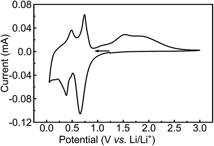 | ||
| Fig. 7 Cyclic voltammetry of MoS2-NR films in ITO at 0.05 mV s−1 scan rate. Electrolytic solution: 1 mol L−1 LiTFSI in PC. | ||
The electrochemical lithium insertion in MoS2-NRs is consistent with the CVs described in the literature for MoS2 with different morphologies: nanorods,15 nanoflakes,49 nanoflowers,50,51 MoS2/graphene composites,52,53 mesoporous MoS2 (ref. 54) and commercial bulk MoS2.14 The first cathodic peak at +0.7 V is attributed to the Li+ insertion in the interlayer sites of MoS2 forming LixMoS2,15 with the correspondent dislodging at +0.7 V.15 The second and more negative peak at +0.3 V can be attributed to the formation of Mo and Li2S from LixMoS2, as suggested from in situ XRD of bulk MoS2 in 1 mol L−1 LiPF6 1![[thin space (1/6-em)]](https://www.rsc.org/images/entities/char_2009.gif) :1 ethylene carbonate:dimethyl carbonate,14 with the correspondent anodic process taking place at +0.4 V. The small cathodic wave at +0.2 V could be attributed to the more negative reduction of Li2S to Li and S.15
:1 ethylene carbonate:dimethyl carbonate,14 with the correspondent anodic process taking place at +0.4 V. The small cathodic wave at +0.2 V could be attributed to the more negative reduction of Li2S to Li and S.15
4 Conclusions
α-MoO3 nanoribbons with high purity of phase and morphology were prepared by a hydrothermal method from MoO3·2H2O. The molybdenum oxide was converted into MoS2 retaining the same nanoribbons morphology by solid–gas reaction with H2 and H2S. Streaming H2S from the beginning of the thermal treatment was a key factor in maintaining the nanoribbons morphology from the oxide in the final MoS2 product. A protective MoS2 outer layer is formed in the oxide preventing the collapsing of the nanoribbons morphology. MoO3 nanoribbons showed distinct electrochromic performance for Li+ insertion, changing coloration from pale to dark blue upon changing the potential negatively. Spectroelectrochemical measurements with a laser in 660 nm showed the presence of two chromophores correspondent to three cathodic peaks and the formation of LixMoO3. Lithium removal from the oxide is however not totally reversible and a hysteresis in absorption as well as in the charge consumed is observed. The voltammetric behavior of MoS2 shows that lithium can be intercalated within the interlayer spacing this material forming LixMoS2, which can be removed in the anodic scan. This template synthesis is a simple method to obtain MoS2 nanoribbons with a controlled morphology (100% of nanoribbons).Conflicts of interest
The authors declare no conflicts of interest.Acknowledgements
The authors acknowledge funding from Brazilian agencies FAPESP Proc. 2015/26308-7, CNPq, the Millennium Institute of Complex Materials (PADCT/MCT) and Rede Nacional de Nanotubos (CNPq/MCT). LV acknowledges the scholarship from FAPESP and the visiting researcher grant from NanoBioss/CNPq (Proc. 402280/2013-0). OPF is grateful for the support from CAPES-PROCAD 2013 Grant 183995. We are indebted to Dr Carlos A. P. Leite and Dr Carla Verissimo for assistance with the TEM and FE-SEM images. LV thanks Dr Juliana Martins de Souza e Silva and Sumanth Ranganathan for comments and discussions, as well as Prof. Cruywagen for sending a hard copy of his paper.References
- P. Monk, R. Mortimer and D. Rosseinsky, Electrochromism and Electrochromic Devices, Cambridge University Press, 2007 Search PubMed.
- D. R. Rosseinsky and R. J. Mortimer, Adv. Mater., 2001, 13, 783–793 CrossRef.
- A. C. Dillon, A. H. Mahan, R. Deshpande, P. A. Parilla, K. M. Jones and S.-H. Lee, Thin Solid Films, 2008, 516, 794–797 CrossRef.
- Z. Wei, L. Wang, M. Zhuo, W. Ni, H. Wang and J. Ma, J. Mater. Chem. A, 2018, 6, 12185–12214 RSC.
- V. S. Saji and C.-W. Lee, ChemSusChem, 2012, 5, 1146–1161 CrossRef PubMed.
- M. E. Spahr, P. Novák, O. Haas and R. Nesper, J. Power Sources, 1995, 54, 346–351 CrossRef.
- T. M. McEvoy, K. J. Stevenson, J. T. Hupp and X. Dang, Langmuir, 2003, 19, 4316–4326 CrossRef.
- C.-S. Hsu, C.-C. Chan, H.-T. Huang, C.-H. Peng and W.-C. Hsu, Thin Solid Films, 2008, 516, 4839–4844 CrossRef.
- L. Cheng, M. Shao, X. Wang and H. Hu, Chem.–Eur. J., 2009, 15, 2310–2316 CrossRef PubMed.
- M. Dhanasankar, K. K. Purushothaman and G. Muralidharan, Solid State Sci., 2010, 12, 246–251 CrossRef.
- M. Wang and K. J. Koski, ACS Nano, 2015, 9, 3226–3233 CrossRef PubMed.
- M.-R. Gao, Y.-F. Xu, J. Jiang and S.-H. Yu, Chem. Soc. Rev., 2013, 42, 2986–3017 RSC.
- T. Stephenson, Z. Li, B. Olsen and D. Mitlin, Energy Environ. Sci., 2014, 7, 209–231 RSC.
- X. Fang, C. Hua, X. Guo, Y. Hu, Z. Wang, X. Gao, F. Wu, J. Wang and L. Chen, Electrochim. Acta, 2012, 81, 155–160 CrossRef.
- U. K. Sen and S. Mitra, J. Solid State Electrochem., 2014, 18, 2701–2708 CrossRef.
- J. Feng, K. Liu, M. Graf, M. Lihter, R. D. Bulushev, D. Dumcenco, D. T. Alexander, D. Krasnozhon, T. Vuletic, A. Kis and A. Radenovic, Nano Lett., 2015, 15, 3431–3438 CrossRef PubMed.
- X. L. Li and Y. D. Li, Chem.–Eur. J., 2003, 9, 2726–2731 CrossRef PubMed.
- G. A. Camacho-Bragado and M. Jose-Yacaman, Appl. Phys. A, 2006, 82, 19–22 CrossRef.
- M. G. Sibi, B. S. Rana, L. N. S. Konathala, G. D. Thakre, S. Saran and A. K. Sinhaa, J. Mater. Res., 2013, 28, 1962–1971 CrossRef.
- G. A. Camacho-Bragado, J. L. Elechiguerra, A. Olivas, S. Fuentes, D. Galvan and M. J. Yacaman, J. Catal., 2005, 234, 182–190 CrossRef.
- H. A. Therese, N. Zink, U. Kolb and W. Tremel, Solid State Sci., 2006, 8, 1133–1137 CrossRef.
- X. W. Lou and H. C. Zeng, Chem. Mater., 2002, 14, 4781–4789 CrossRef.
- M. A. Albiter, R. Huirache-Acua, F. Paraguay-Delgado, J. L. Rico and G. Alonso-Nuez, Nanotechnology, 2006, 17, 3473–3481 CrossRef PubMed.
- Y. Feldman, E. Wasserman, D. J. Srolovitz and R. Tenne, Science, 1995, 267, 222–225 CrossRef PubMed.
- A. Zak, Y. Feldman, V. Alperovich, R. Rosentsveig and R. Tenne, J. Am. Chem. Soc., 2000, 122, 11108–11116 CrossRef.
- Y. Feldman, G. L. Frey, M. Homyonfer, V. Lyakhovitskaya, L. Margulis, H. Cohen, G. Hodes, J. L. Hutchison and R. Tenne, J. Am. Chem. Soc., 1996, 118, 5362–5367 CrossRef.
- Y. Feldman, V. Lyakhovitskaya and R. Tenne, J. Am. Chem. Soc., 1998, 120, 4176–4183 CrossRef.
- R. Rosentsveig, A. Margolin, A. Gorodnev, R. Popovitz-Biro, Y. Feldman, L. Rapoport, Y. Novema, G. Naveh and R. Tenne, J. Mater. Chem., 2009, 19, 4368–4374 RSC.
- G. A. Camacho-Bragado, J. L. Elechiguerra and M. J. Yacaman, Mater. Charact., 2008, 59, 204–212 CrossRef.
- G. R. Patzke, A. Michailovski, F. Krumeich, R. Nesper, J. D. Grunwaldt and A. Baiker, Chem. Mater., 2004, 16, 1126–1134 CrossRef.
- J. J. Cruywagen and J. B. B. Heyns, S. Afr. J. Chem., 1981, 34, 118–120 Search PubMed.
- S. Balendhran, S. Walia, H. Nili, J. Z. Ou, S. Zhuiykov, R. B. Kaner, S. Sriram, M. Bhaskaran and K. Kalantar-zadeh, Adv. Funct. Mater., 2013, 23, 3952–3970 CrossRef.
- Y. P. Chen, C. L. Lu, L. Xu, Y. Ma, W. H. Hou and J. J. Zhu, CrystEngComm, 2010, 12, 3740–3747 RSC.
- A. Michailovski and G. R. Patzke, Chem.–Eur. J., 2006, 12, 9122–9134 CrossRef PubMed.
- A. Chithambararaj and A. C. Bose, J. Alloys Compd., 2011, 509, 8105–8110 CrossRef.
- J. V. Silveira, L. L. Vieira, J. Mendes Filho, A. J. C. Sampaio, O. L. Alves and A. G. Souza Filho, J. Raman Spectrosc., 2012, 43, 1407–1412 CrossRef.
- J. V. Silveira, L. L. Vieira, A. L. Aguiar, P. T. C. Freire, J. Mendes Filho, O. L. Alves and A. G. Souza Filho, Spectrochim. Acta, Part A, 2018, 193, 47–53 CrossRef PubMed.
- Q. P. Ding, H. B. Huang, J. H. Duan, J. F. Gong, S. G. Yang, X. N. Zhao and Y. W. Du, J. Cryst. Growth, 2006, 294, 304–308 CrossRef.
- D. Liu, W. W. Lei, J. Hao, D. D. Liu, B. B. Liu, X. Wang, X. H. Chen, Q. L. Cui, G. T. Zou, J. Liu and S. Jiang, J. Appl. Phys., 2009, 105, 0235131–0235137 Search PubMed.
- L. Seguin, M. Figlarz, R. Cavagnat and J.-C. Lassègues, Spectrochim. Acta, Part A, 1995, 51, 1323–1344 CrossRef.
- S.-H. Lee, M. J. Seong, C. E. Tracy, A. Mascarenhas, J. R. Pitts and S. K. Deb, Solid State Ionics, 2002, 147, 129–133 CrossRef.
- G. Mestl, N. F. D. Verbruggen, E. Bosch and H. Knözinger, Langmuir, 1996, 12, 2961–2968 CrossRef.
- M. Virsek, A. Jesih, I. Milosevic, M. Damnjanovic and M. Remskar, Surf. Sci., 2007, 601, 2868–2872 CrossRef.
- B. Windom, W. G. Sawyer and D. Hahn, Tribol. Lett., 2011, 42, 301–310 CrossRef.
- G. L. Frey, R. Tenne, M. J. Matthews, M. S. Dresselhaus and G. Dresselhaus, Phys. Rev. B: Condens. Matter Mater. Phys., 1999, 60, 2883–2892 CrossRef.
- U. K. Sen and S. Mitra, RSC Adv., 2012, 2, 11123–11131 RSC.
- T. Brezesinski, J. Wang, S. H. Tolbert and B. Dunn, Nat. Mater., 2010, 9, 146–151 CrossRef PubMed.
- T. Stephenson, Z. Li, B. Olsen and D. Mitlin, Energy Environ. Sci., 2014, 7, 209–231 RSC.
- C. Feng, J. Ma, H. Li, R. Zeng, Z. Guo and H. Liu, Mater. Res. Bull., 2009, 44, 1811–1815 CrossRef.
- H. Li, W. Li, L. Ma, W. Chen and J. Wang, J. Alloys Compd., 2009, 471, 442–447 CrossRef.
- U. K. Sen and S. Mitra, ACS Appl. Mater. Interfaces, 2013, 5, 1240–1247 CrossRef PubMed.
- K. Chang and W. Chen, ACS Nano, 2011, 5, 4720–4728 CrossRef PubMed.
- L. Ma, G. Huang, W. Chen, Z. Wang, J. Ye, H. Li, D. Chen and J. Y. Lee, J. Power Sources, 2014, 264, 262–271 CrossRef.
- H. Liu, D. Su, R. Zhou, B. Sun, G. Wang and S. Z. Qiao, Adv. Energy Mater., 2012, 2, 970–975 CrossRef.
Footnotes |
| † Electronic supplementary information (ESI) available. See DOI: 10.1039/c8ra05988h |
| ‡ Current address: Fraunhofer Institute for Interfacial Engineering and Biotechnology IGB, Assistant Bio, Electro and Chemocatalysis BioCat, Straubing branch, Schulgasse 11a, 94315 Straubing, Germany. |
| This journal is © The Royal Society of Chemistry 2018 |