 Open Access Article
Bio-inspired antifogging PDMS coupled micro-pillared superhydrophobic arrays and SiO2 coatings†
Zhiwu Han a,
Xiaoming Fenga,
Zhibin Jiaoa,
Ze Wanga,
Junqiu Zhangab,
Jie Zhao
 a,
Shichao Niu
 *a and
Luquan Rena
aKey Laboratory of Bionic Engineering, Ministry of Education, Jilin University, Changchun 130022, China. E-mail: niiushichao@jlu.edu.cn
bDepartment of Mechanical Engineering, Columbia University, New York 10027, USA
First published on 25th July 2018
Abstract
In this work, inspired by some typical creatures from nature with superhydrophobic surfaces, a bio-inspired antifogging PDMS is designed and fabricated successfully using UV lithography and a template method. First, we fabricated an SU-8 layer with a bio-inspired micro-pillared array (MPA) using traditional UV lithography. Then, it was used as a template to fabricate a PDMS film (PF). After that, it was chemically modified with SiO2 coatings. It was found that the PF coupled with sprayed SiO2 coatings and a MPA have a higher water contact angle (CA) of 158° and a lower contact angle hysteresis (CAH) of less than 2°. Water drops can be separated from this bio-inspired PDMS surface within 86.8 ms. More importantly, this film’s antifogging property is superior, with a recovery time of less than 13 s, which is significantly superior to that of the flat PF and the PF with the MPA. Afterwards, FTIR was applied to analyse the surface chemistry features and suggested that the bio-inspired PF has extremely low surface tension. So, it can be confirmed that an excellent superhydrophobic antifogging property has been achieved on the surface of the PF. Meanwhile, the microscopic and macroscopic dynamic movement behaviour of the fog drops was further observed. Then, the underlying antifogging mechanism was also revealed. These properties mainly benefit from the coupling effect of intermolecular attraction of droplets, chemical compositions (nanometre roughness SiO2) and the physical structures (MPA). The investigations offer a promising way to handily design and fabricate multiscale hierarchical structures on polymers and other materials. More importantly, these findings suggest great potential value for specific antifogging applications in display devices, transport, agricultural greenhouses, food packaging and solar products, especially in continuous harsh fogging conditions.
1. Introduction
Fog formation and accumulation on the surfaces of equipment, such as eyeglasses, windshields, goggles, lenses and display devices in analytical and medical instruments, are known to cause serious economic and safety problems.1–3 The fundamental principle of antifogging materials is to regulate the interaction between water drops and the solid surface via surface chemical composition as well as the rough features’ size and geometry to ensure appropriate wettability.4,5 Antifogging surfaces with hydrophilic or even superhydrophilic wetting behaviour have drawn wide attention due to their ability to significantly reduce light scattering by only allowing fog droplets to condensate in a film-like form.6–9 However, under harsh fogging conditions, these surfaces may exhibit frost formation or excess and inhomogeneous water condensation, which would cause irreversible catastrophic results, such as ceasing the operation, impairing the efficiency or even paralyzing the entire system, especially when considering applications in aircrafts, wind turbines, high-voltage power transmission, telecommunications equipment and heat exchangers.1 Superhydrophobic-induced antifogging behaviour not only can improve the evaporation rate of fog because of its high CA to the tiny water droplets,10 but can also induce tiny condensed droplets to merge with each other easily and then shed from the surface. This prevents moisture or microscale fog droplets from nucleating on a surface and so that the surface remains dry.11–13Bio-inspired micro-/nanopatterned structures combined with a variety of material substrates can improve the water repellency performance, even leading to the enhancement of the antifogging ability.14–17 Compared with these materials, polymer materials have lots of peculiar attributes, such as low cost, good deformability and ease of fabrication and so they have broader application prospects.18,19 Polydimethylsiloxane (PDMS) is typical example of these materials.20,21 PDMS is inherently water repellent and one of the frequently-used surface modifiers to create superhydrophobic surfaces.22 Introducing different surface textures such as microwell arrays,23 femtosecond parallel arrays24 or other 3D pattern dependent structures25 into PDMS surfaces can create some chemistry/topography-combined superhydrophobic surfaces. However, a plausible issue has recently arisen. Superhydrophobicity is not the only criteria for generating high-performance antifogging or even anti-ice surfaces.26 Besides, most of the methods are not scalable for industrial level. In fact, PDMS microscale pillar arrays can achieve higher CAs over 150° without further coatings or treatment steps,27,28 but their antifogging ability is not obvious because of the good adhesion to droplets of PDMS itself. Some investigations on antifogging function involving PDMS have been reported, for example, the involved PDMS layer was treated with O2 plasma to convert into highly porous silica films,29 or as a “seed layer” by photochemical oxidation,30 the common purpose was to result in a superhydrophilic antifogging layer. In addition, Zheng and co-workers11 first designed a composite micro/nanostructure surface using a polyvinylidene difluoride polymer as the substrate, showing excellent antifogging and icing-delay properties. Next they presented a series of surfaces combined with nanohairs and micropillar arrays using PDMS as a negative replica and then epoxy as the substrate, demonstrating the excellent anti-icing abilities of the surface.15 This provides the inspiration for our work as, to the best of our knowledge, the antifogging performance using PDMS directly as the substrate has rarely been characterized in detail.
Herein, we designed the surface asperities to take the form of a regular micro-pillared array (MPA) using a PDMS film (PF) in combination with a silicon dioxide (SiO2) modification. In this fabrication, an SU-8 mold of negative well arrays was obtained using traditional UV lithography, then a soft replication method was adopted to obtain a PF with a MPA as the substrate. Subsequent SiO2 nanometer coatings were sprayed on the surface of the PF with the MPA. Depositing a layer of SiO2 on the surface of the PF with the MPA using a spray coating technique makes PDMS with a superhydrophobic antifogging property. The dimensional uniformity and quality of the as-prepared PF was characterized with the help of field emission scanning electronic microscopy (FESEM). Fourier transform infrared spectroscopy (FTIR) results indicated that both the functional groups of –CH2 and –CH3 existed on the surfaces of the bio-inspired PF samples, which not only increases their hydrophobicity dramatically, but also decreases their water adhesion performance. So, the superhydrophobic antifogging performance of the bio-inspired PF is ensured. Meanwhile, a set of optimized models were generated to illustrate the fabrication process. Moreover, the final antifogging behaviors were also revealed. The antifogging properties of the PF were characterized experimentally using a spray simulation system and an optical CA measuring device. The time-lapse transmittance measurements demonstrated that the as-prepared PF possessed a superior fogging recovery property because it can reach a plateau in far less time (<13 s). It also suggested a reliable optical performance in practical outdoor conditions. Furthermore, the dynamic antifogging behaviors of the PF coupled with SiO2 coatings and the MPA were observed carefully, verifying that the MPA can get dry and the fog drops can drop from the as-modified PF. It was confirmed that PF coupled with sprayed SiO2 coatings and the MPA possesses excellent superhydrophobicity and antifogging behaviors.
2. Results and discussion
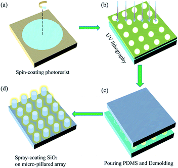
In this work, we designed a matrix of geometries made of periodic structures on a PDMS substrate. The overall process of preparation is shown in Fig. 1. Briefly, a clean glass slide was spin-coated with a negative photoresist SU-8, the spinning speed determined the thickness of the SU-8 coating; a photomask containing the circle-shaped arrays was utilized in traditional UV lithography; the unexposed SU-8 was flushed off in the developer, leaving the circular micro-hole arrays standing on the glass slide; a mixture of the PDMS pre-polymer and curing agent in a 10![[thin space (1/6-em)]](https://www.rsc.org/images/entities/char_2009.gif) :
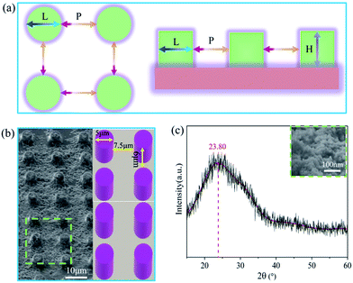
:![[thin space (1/6-em)]](https://www.rsc.org/images/entities/char_2009.gif) 1 mixture (by weight) was degassed using a vacuum chamber and carefully poured onto the SU-8 masters; after curing at 80 °C for 1 h, the PDMS sample was gently peeled from the mold; the commercial SiO2 coating agent was sprayed on top of the as-prepared PDMS. As illustrated in Fig. 2a, the side length of the pillar (L) is about 5 μm, the pitch between neighboring pillars (P) is about 7.5 μm and the nominal height of the pillar (H) is about 6 μm. The quality and uniformity of the pillars were inspected using FESEM. The FESEM sample was titled at 45° to reveal the actual structures. Fig. 2b shows the PDMS coating has a negligible effect on the global structure of the MPA, though the individual micro-pillar was coated with nanoscale SiO2 (Fig. 2c). The FESEM results indicate that the as-prepared PF possessed a rough surface and contained many bumps.
1 mixture (by weight) was degassed using a vacuum chamber and carefully poured onto the SU-8 masters; after curing at 80 °C for 1 h, the PDMS sample was gently peeled from the mold; the commercial SiO2 coating agent was sprayed on top of the as-prepared PDMS. As illustrated in Fig. 2a, the side length of the pillar (L) is about 5 μm, the pitch between neighboring pillars (P) is about 7.5 μm and the nominal height of the pillar (H) is about 6 μm. The quality and uniformity of the pillars were inspected using FESEM. The FESEM sample was titled at 45° to reveal the actual structures. Fig. 2b shows the PDMS coating has a negligible effect on the global structure of the MPA, though the individual micro-pillar was coated with nanoscale SiO2 (Fig. 2c). The FESEM results indicate that the as-prepared PF possessed a rough surface and contained many bumps.
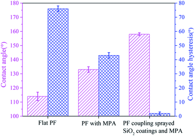
The wettability properties of the flat PF, PF with the MPA and PF coupled with sprayed SiO2 coatings and the MPA were examined separately via an optical CA measuring device based on a sessile drop technique. An average of five measurements on each sample is effective. Fig. 3 shows the water CA of the three PFs was linearly increased and the hydrophobicity of flat PF and PF with the MPA was compared, exhibiting water CAs of 114° and 133°, respectively. The PF coupled with sprayed SiO2 coatings and the MPA was found to be superhydrophobic, showing an average water CA of 158°. This indicated that the change in surface structure results from the MPA significantly increasing the water CA, rendering the surface superhydrophobic. The superhydrophobic property was elucidated using the Cassie–Baxter model,31 suggesting that the microstructure on a low-surface-energy material significantly improved the superhydrophobicity of the surface.
The effective CA of the droplets can be regulated by the equation cos![[thin space (1/6-em)]](https://www.rsc.org/images/entities/char_2009.gif) θc = fs
θc = fs![[thin space (1/6-em)]](https://www.rsc.org/images/entities/char_2009.gif) cos
cos![[thin space (1/6-em)]](https://www.rsc.org/images/entities/char_2009.gif) θs + fv
θs + fv![[thin space (1/6-em)]](https://www.rsc.org/images/entities/char_2009.gif) cos
cos![[thin space (1/6-em)]](https://www.rsc.org/images/entities/char_2009.gif) θv, where θs and θv are the CA of the liquid contacting with solid and vapor parts and fs and fv are the area fractions of the solid and vapor on the surface. If rough structures on a surface can generate entrapped air pockets, in such circumstance, fs + fv = 1 and θv = 180°. θc can be calculated by the following equation,
θv, where θs and θv are the CA of the liquid contacting with solid and vapor parts and fs and fv are the area fractions of the solid and vapor on the surface. If rough structures on a surface can generate entrapped air pockets, in such circumstance, fs + fv = 1 and θv = 180°. θc can be calculated by the following equation,
cos![[thin space (1/6-em)]](https://www.rsc.org/images/entities/char_2009.gif) θc = fs(cos θc = fs(cos![[thin space (1/6-em)]](https://www.rsc.org/images/entities/char_2009.gif) θs + 1) − 1 θs + 1) − 1
| (1) |
In addition, a superhydrophobic surface with low adhesion to droplets is a crucial index of antifogging materials. It is found that the water adhesion on both the flat PF and the PF with the MPA was high. Therefore, our starting surface was hydrophobic with high adhesion. Amazingly, the PF coupled with sprayed SiO2 coatings and the MPA had a low CAH of less than 2°. From a thermodynamic point of view, eliminating a liquid from its solid substrate requires the energy to overcome the adhesion.32 The basic relation between the work of adhesion and surface wettability is given by the Dupre–Yong equation,33
We = γlv(1 + cos![[thin space (1/6-em)]](https://www.rsc.org/images/entities/char_2009.gif) θc) θc)
| (2) |
The water droplet bounce behaviors on the as-prepared PF were recorded with the help of a high-speed video camera when a 15.6 μL water droplet was dropped from a height of 54.8 mm (see ESI Video S2†). The dropping height was determined by the maximum height avoiding droplet fragmentation upon impact with the surface, ensuring maximum droplet momentum. This droplet volume (≈16 μL) was found to be optimum as the droplet could be replicated easily and fell under its own weight when dropped from a 23 gauge dispensing tip. As shown in Fig. 4, the water droplet deformed quickly after contact with the as-prepared PF. The initial impacting velocity of the droplet was 0.94 ms−1. At 3.1 ms, the spherical water droplet reached a disc-like form. Then, the water drop began to bounce twice and finally completely separated from surface of the as-prepared PF within 86.8 ms, which further illustrates the excellent superhydrophobic and low adhesion properties.
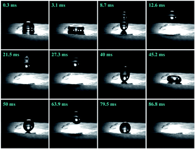 | ||
| Fig. 4 Bounce dynamics of a water droplet impacting with the PF coupled with sprayed SiO2 coatings and the MPA surface. | ||
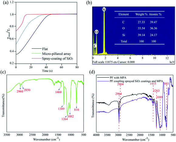
Furthermore, since fogging results in a certain degree of transmittance loss, we quantified the response of the flat PF, PF with the MPA and PF coupled with sprayed SiO2 coatings and the MPA to fogging at regular intervals (Tt) until the original transmittance (Tmax) was restored. In order to characterize the antifogging recovery property, the variation trends of the time-lapse transmittance measurements of the three PFs were performed after being sprayed by the generated fog. For this purpose, we built a spray simulation system to characterize their antifogging properties.34 The PF was fixed by a clip which was adjusted to be perpendicular to the light beam. As shown in Fig. 5a, recovery from fogging was much faster for the PF coupled with sprayed SiO2 coatings and the MPA, with Tmax/Tt reaching a plateau in far less time than the others. It was confirmed that the PF coupled with sprayed SiO2 coating and the MPA possesses a superior ability for antifogging recovery, especially in wet and humid environments.35
In order to clarify the reasons that the PF coupled with sprayed SiO2 coating and the MPA possessed the superhydrophobic-antifogging function we investigated the chemical composition of the as-prepared PF surface. Fig. 5b shows the EDS spectra of the as-prepared PF and the results indicated that the fabricated PF is composed of three elements, carbon (C), silicon (Si) and oxygen (O). FTIR spectra of the commercial SiO2 coating agent, the PF with the MPA and the PF coupled with sprayed SiO2 coatings and the MPA were obtained. The FTIR spectrum of the commercial SiO2 coating agent is shown in Fig. 5c. The peak at 810 cm−1 is due to Si–O–Si symmetric stretching, and the Si–O–Si asymmetric vibration is at 1082 cm−1. The peaks at 1264 and 2960 cm−1 correspond to the symmetric bending vibration of Si–CH3 and symmetric stretching vibration of Si–CH3, respectively. The peaks at 850 and 1405 cm−1 are due to the Si–C bending and Si–C stretching vibrations, respectively. The Si–CH2 stretching band is at 2850 cm−1 and the peaks at 1389 and 1460 cm−1 are due to the bending vibration of Si–CH2.36 The FTIR spectrum of the PF with the MPA and the PF coupled with sprayed SiO2 coatings and the MPA is shown in Fig. 5d. The peak at 1089 is attributed to the Si–O–Si stretching vibration. The peaks at around 1263 and 803 cm−1 are assigned to the Si–C groups. Other characteristic peaks in the spectrum are assigned to the –CH, –CH2 and –CH3 groups of the polymer backbone (2964 cm−1, 2904 cm−1 and 1415 cm−1, respectively). It could be observed that the FTIR spectrum of the modified PF is consistent with the FTIR spectrum of the untreated PF.37 The above results not only suggest the commercial SiO2 coating agent without any impurities, but also the as-prepared PF, was enriched with extreme superhydrophobicity and low adhesion, due to the hydrophobic functional groups (–CH2 and –CH3) of the SiO2 coating.
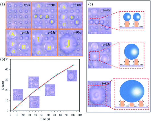
To examine the antifogging property more intuitively, a 3D ultra-depth stereoscopic microscope was used to observe the micro-dynamic behaviour of fog drops on the PF coupled with sprayed SiO2 coatings and the MPA surface (see ESI Video S3†). First, many individual fog drops with a spherical appearance were occurring on the top of the micropillars. As time went on, we found some tiny fog drops began to merge with each other and form new fog drops. As shown in Fig. 6, fog drops A–E were growing smoothly (t = 20 s). Subsequently, fog drops B and C coalesced into larger fog drop F (t = 30 s), fog drops D and E coalesced into larger fog drop H (t = 45 s) and fog drops A and F coalesced into larger droplet I (t = 55 s). Then, fog drops H and I merged with fog drop G and formed fog drop J (t = 90 s). This indicated that the condensed fog drops can be in Cassie’s state. We theorised that a de-wetting transition phenomenon may occur on the surface,38 then the released surface energy can propel the fog drop jumping or self-removal from the surface.39,40 Furthermore, when this flying fog drop touched another constrained fog drop, a transition would again be stimulated. Due to the occurrence of the de-wetting transitions and the self-removal phenomenon, the MPA can get dry and the fog drops can drop from the PF by means of the low surface adhesion.
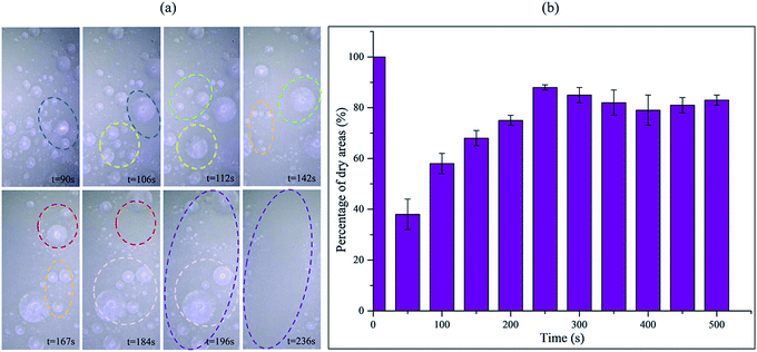
In order to verify our hypothesis about antifogging behaviour on the PF coupled with sprayed SiO2 coatings and the MPA surface, the macro-dynamic process of fog drop movement was recorded using a 3D ultra-depth stereoscopic microscope (see ESI Video S4†). As shown in Fig. 7a, the fog spray was applied to the surfaces, some tiny fog drops initially condensed on the surface and subsequently the fog drops became gradually larger. As time went on, we amazingly found the same phenomenon as Fig. 6, that some tiny fog drops began to merge with each other and form larger fog drops (see the same color circles from t = 90 s to t = 196 s). In addition, when the fog drops grew to a certain size, the same phenomenon occurred as in ESI Video S5,† that these fog drops began to roll off suddenly. It is interesting that this roll-off performance removed some circumjacent tiny fog drops, sweeping the surface clean and keeping the area dry (see purple circle at t = 236 s). This is consistent with our previous conjecture and demonstrated the excellent antifogging property of the as-prepared PF surface. To evaluate the antifogging ability of the PF coupled with sprayed SiO2 coatings and the MPA surface, we estimated the percentage of dry areas versus time, as shown in Fig. 7b, at ∼50 s, the percentage was lower, but the percentage increased suddenly after ∼200 s, and the percentage was maintained at ∼83% from ∼250 to 500 s on the whole. This demonstrated the superior antifogging property of the PF coupled with sprayed SiO2 coatings and the MPA surface.
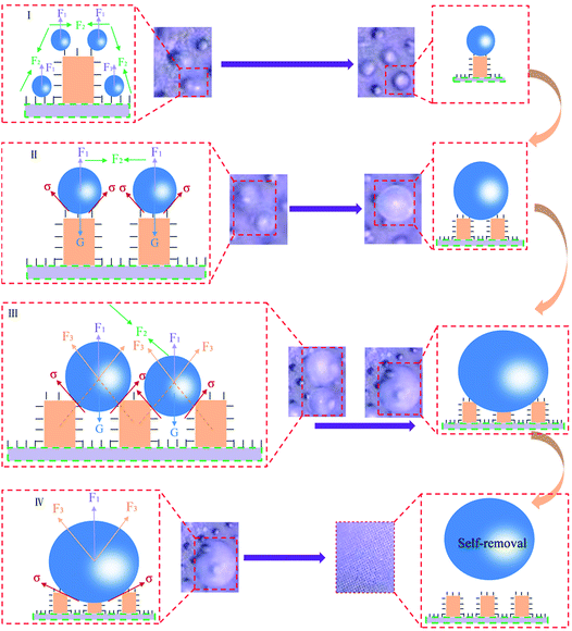
In order to further reveal the internal antifogging mechanism of the PF coupled with sprayed SiO2 coating and the MPA, one possible reasonable explanation for these findings was that the synergistic effect of the droplets intermolecular attraction, chemical compositions and the MPA was the key factor in realizing the superhydrophobic antifogging property. On one hand, the low surface energy methylated (–CH3 and –CH2) components resulted from the SiO2 nanometer coatings, which further increased the PF surface hydrophobicity and dramatically decreased the PF surface adhesion to water droplets. Indeed, the sliding angle for the water drops occurred for a CAH of less than 2°. Since the water drops rolled off easily on the PF surface, we can assume that the water drops stayed on the top of the MPA without penetrating the interpillar areas, and then induced tiny condensed droplets to merge with each other easily until shed from the surface. Moreover, the evaporation rate of fog drops was also improved.41 Physically, the fog drops would remain repulsive to the MPA due to the surface forces having sufficient magnitude to suspend liquid against the downward pull of gravity (or other body forces) (see ESI Videos S6 and S7†). As a whole, the water molecules were affected by a repulsion force of the material itself (F1), intermolecular attraction (F2), a repulsion force of micro-pillared arrays (F3), surface tension (σ) and their own gravity (G) (Fig. 8).
On the other hand, it is a universal strategy to construct a superhydrophobic surface by creating surface roughness onto a low surface energy material. Interestingly, the SiO2-sprayed MPA played a significant role in amplifying the PF’s intrinsic hydrophobicity, which dramatically increased the surface roughness. Specifically, the pillars retained their microscale geometrical characteristics and also exhibited nanometer roughness due to the presence of the SiO2 coating. The combination of the micro/nano-roughness as well as the well-known water-repellent chemical properties of the PDMS made the patterned surfaces superhydrophobic. Previous researchers have reported that the relationships between CA and roughness ratio in two different wettability states were quantitatively described as the Wenzel model and the Cassie–Baxter model42 which indicated that the true CA of a flat hydrophobic surface would be lower with the increase in surface asperities. The very low water adhesion was due to the inherent property of the SiO2 coatings in combination with the geometrical features of the MPA. Apparently, it was the hierarchical amplification effect of SiO2-sprayed MPA that brought big rewards for the achievement of the superhydrophobic antifogging surface. In addition, with the increase in the hydrophobic specific surface that arose from the SiO2-sprayed MPA, the PF surface free energy was obviously reduced. According to energy minimization theory,43 once a droplet coalesces with the adjacent droplets, the released surface energy will overcome droplet adhesion, which may induce the fog drops from a Wenzel state to a Cassie–Baxter state,31 so that coalescing fog droplets can self-remove from PF surfaces. Consequently, the transmittance of the PF coupled with sprayed SiO2 coatings and the MPA would recover to the initial state. These were exactly consistent with the results of the transmittance spectra.
3. Conclusions
In summary, an antifogging PDMS, inspired by some typical creatures from nature with superhydrophobic surfaces, was designed and fabricated successfully via traditional UV lithography combined with a soft replication and subsequent spray coating technique. First, the dimensional uniformity and quality of the bio-inspired PF was characterized using FESEM. It was confirmed that this bio-inspired PF had a coupling surface structure integrated MPA and functionalized SiO2 coating. FTIR results indicated that both the functional groups of –CH2 and –CH3 existed on the surfaces of the bio-inspired PF samples.It not only increased its hydrophobicity dramatically, but also decreased its water adhesion property, ensuring the PF surface achieved superhydrophobic antifogging performance. Meanwhile, a set of optimized models were generated to illustrate the fabrication process. Moreover, the final antifogging behaviors were also revealed. The antifogging properties of PF coupled with sprayed SiO2 coating and the MPA were characterized experimentally using a spray simulation system and optical CA measuring devices. The time-lapse transmittance measurements demonstrated that the bio-inspired PF also possessed superior fogging recovery property (less than 13 s). It confirmed the reliable optical performance of this advanced antifogging material in practical outdoor conditions. Furthermore, dynamic antifogging behaviors of the bio-inspired PF coupled with sprayed SiO2 coatings and the MPA were also observed carefully. It can be confirmed that the bio-inspired PF possesses excellent superhydrophobicity and antifogging behaviours. It is anticipated that the findings reported here provide direct guidance for the future design of superhydrophobic antifogging materials on polymers and other material substrates, and suggest great potential value for specific antifogging applications, such as solar cell panels and window buildings.
4. Experimental section
4.1 Materials and chemical reagents
Acetone, anhydrous ethanol and deionized water were purchased from commercial sources in the highest available purity. The negative photoresist SU-8 2005 and its developer were obtained from MicroChem Corp. Glass slides were used for the substrates. The elastomer PDMS Sylgard 184 was purchased from Dow Corning. The SiO2 coating agent was purchased from Changzhou Nanocoatings Co., Ltd.4.2 Preparation of the CMHA
The procedures were performed as follows: first, glass slides (approximately 4 × 3 cm2) were cleaned for 10 min. The substrate was dried at 200 °C for 30 min. Next, SU-8 photoresist was dispensed on a glass slide through a spin-coating program (500 rpm for 10 s and 3000 rpm for 30 s). The substrate was soft baked on a level hotplate at 103 °C for 6 min. In addition, the substrate was treated using traditional UV lithography and UV exposure (exposure energy at 158 mJ cm−2 for 10 s) was performed perpendicularly to a photomask of circle-shaped array patterns. Then a post exposure bake step was carried out at 98 °C for 5 min to harden the SU-8 layer. The thickness of the resulting film was approximately 6 μm. Finally, the substrate was immersed in the developer for 30 s. The solution was agitated using a tweezer to obtain the uniform SU-8 CMHA on the glass substrate.4.3 Preparation of the micro-pillared array (MPA)
The CMHA on the glass substrate was used as a master pattern. The procedures were performed as follows: first, the pre-polymer and the curing agent were mixed uniformly and stirred in a glass beaker to synthesize the PDMS. Second, the PDMS was poured over the photoresist layer gently and the assembly was moved into the vacuum chamber for 40 min to remove air bubbles, next it was heated in a drying oven at 80 °C for 1 h to completely cure the PDMS. Last, the solidified PDMS was peeled off from the glass substrate and the MPA was transferred to the PF.4.4 Preparation of the sprayed SiO2 coatings on the MPA
A commercial SiO2 coating agent was sprayed on top of the as-prepared PDMS. A spray coating setup was used to deposit the particles. The distance between the sample and the nozzle head was approximately 15 cm. The samples were baked in a drying oven at 80 °C for 20 min. The spray coating and heating processes were performed twice.4.5 Characteristics of the prepared samples
The uniformity and quality of the fabricated sample was inspected with the help of FESEM (JSM-6700F, JEOL) at an accelerating voltage of 2.0 kV. The static water CAs of the sample surfaces were estimated with an optical CA measuring device (OCA20 data physics, Germany). The advancing contact angles (ACAs) and receding contact angles (RCAs) were tested using a method in which the droplets were enlarged from 7 to 14 μL to obtain ACAs and shrunk from 14 to 7 μL to obtain RCAs. The CAH was measured by inclining the sample until the droplet start rolling. An XRD sample was fixed on the sample stage to keep it even. The commercial SiO2 coating agent was characterized using an X-ray diffractometer (Rigaku). The experiment data were collected from 15 to 60°. The compositions and distributions of the main elements in the PF coupled with sprayed SiO2 coating and the MPA were measured using EDS (OXFORD X-MaxN 150). The chemical bonds of the samples were examined using FTIR spectroscopy (IRAffinity-1S). The transmittance spectra of the three PFs were obtained using a miniature fiber-optic spectrometer (Ocean Optics USB 4000) and the light spot size of the incident beam was about 5 mm in diameter. The spectrometer was carefully calibrated with STD-WS, a standard white board certified by the National Institute of Metrology of China.4.6 Observation of fog drops condensation
The samples were fixed horizontally on the object stage. The spray of a humidifier was used to generate condensed fog drops on the sample surface. After the surfaces were sprayed, the microscopic and macroscopic dynamic behaviour of the movement of the fog drops on the PF coupled with sprayed SiO2 coating and the MPA surface were simultaneously observed using the 3D ultra-depth stereoscopic microscope (KEYENCE VHX-5000). The condensation experiments were repeated several times. The laboratory temperature was measured at 29 °C with a relative humidity of 40%.4.7 Spray simulation
The spray simulation system includes a tungsten-halogen lamp (Ocean Optics LS-1-LL), optical fiber, ultrasonic humidifier (YADU YC-X100E), optical-collimated bracket, a spectrograph (Ocean Optics USB 4000) and a laptop computer.Conflicts of interest
There are no conflicts to declare.Acknowledgements
This work was supported by the National Natural Science Foundation of China (No. 51325501, 51505183 and 51675220), JLU Science and Technology Innovative Research Team (No. 2017TD-04), Joint Construction Project of Jilin University and Jilin Province (No. SF2017-3-4), Graduate Innovation Fund of Jilin University (No. 2017010), Special Funding from China Postdoctoral Science Foundation (No. 2018T110246) and Outstanding Young Talent Fund of Jilin Province (No. 20170520095JH).References
- Q. Zhang, B. Jin, B. Wang, Y. Fu, X. Zhan and F. Chen, Ind. Eng. Chem. Res., 2017, 56, 2754–2763 CrossRef.
- T. Zhang, Q. Yu, J. Wang and T. Wu, Ind. Eng. Chem. Res., 2018, 57, 4577–4584 CrossRef.
- F. Wang and H. Liu, J. Phys. Chem. C, 2018, 122, 3434–3442 CrossRef.
- Z. Han, X. Feng, Z. Guo, S. Niu and L. Ren, Adv. Mater., 2018, 30, 1704652 CrossRef PubMed.
- T. Mouterde, G. Lehoucq, S. Xavier, A. Checco, C. T. Black, A. Rahman, T. Midavaine, C. Clanet and D. Quéré, Nat. Mater., 2017, 16, 658–663 CrossRef PubMed.
- J. Zhao, A. Meyer, L. Ma and W. Ming, Chem. Commun., 2013, 49, 11764–11766 RSC.
- F. Xu, X. Li, Y. Li and J. Sun, ACS Appl. Mater. Interfaces, 2017, 9, 27955–27963 CrossRef PubMed.
- F. Liu, J. Shen, W. Zhou, S. Zhang and L. Wan, RSC Adv., 2017, 7, 15992–15996 RSC.
- Z. Bai, Y. Hu, S. Yan, W. Shan and C. Wei, RSC Adv., 2017, 7, 1966–1974 RSC.
- Q. Shang and Y. Zhou, Ceram. Int., 2016, 42, 8706–8712 CrossRef.
- M. Wen, L. Wang, M. Zhang, L. Jiang and Y. Zheng, ACS Appl. Mater. Interfaces, 2014, 6, 3963–3968 CrossRef PubMed.
- R. Wen, S. Xu, D. Zhao, Y.-C. Lee, X. Ma and R. Yang, ACS Appl. Mater. Interfaces, 2017, 9, 44911–44921 CrossRef PubMed.
- P. Zhang, Y. Maeda, F. Lv, Y. Takata and D. Orejon, ACS Appl. Mater. Interfaces, 2017, 9, 35391–35403 CrossRef PubMed.
- M. He, Y. Ding, J. Chen and Y. Song, ACS Nano, 2016, 10, 9456–9462 CrossRef PubMed.
- W. Shi, L. Wang, Z. Guo and Y. Zheng, Adv. Mater. Interfaces, 2015, 2, 1500352 CrossRef.
- H. K. Raut, S. S. Dinachali, Y. C. Loke, R. Ganesan, K. K. Ansah-Antwi, A. Gora, E. H. Khoo, V. A. Ganesh, M. S. Saifullah and S. Ramakrishna, ACS Nano, 2015, 9, 1305–1314 CrossRef PubMed.
- J. Lomga, P. Varshney, D. Nanda, M. Satapathy, S. Mohapatra and A. Kumar, J. Alloys Compd., 2017, 702, 161–170 CrossRef.
- L. Ai, J. Zhang, X. Li, X. Zhang, Y. Lu and W. Song, ACS Appl. Mater. Interfaces, 2018, 10, 4993–4999 CrossRef PubMed.
- S. Das, S. Kumar, S. K. Samal, S. Mohanty and S. K. Nayak, Ind. Eng. Chem. Res., 2018, 57, 2727–2745 CrossRef.
- K. H. Oh, H. S. Kang, M. J. Choo, D. H. Jang, D. Lee, D. G. Lee, T. H. Kim, Y. T. Hong, J. K. Park and H. T. Kim, Adv. Mater., 2015, 27, 2974–2980 CrossRef PubMed.
- I. Hwang, D. Choi, S. Lee, J. H. Seo, K.-H. Kim, I. Yoon and K. Seo, ACS Appl. Mater. Interfaces, 2017, 9, 21276–21282 CrossRef PubMed.
- M. J. Nine, M. A. Cole, L. Johnson, D. N. Tran and D. Losic, ACS Appl. Mater. Interfaces, 2015, 7, 28482–28493 CrossRef PubMed.
- J. Yong, F. Chen, Q. Yang, D. Zhang, H. Bian, G. Du, J. Si, X. Meng and X. Hou, Langmuir, 2013, 29, 3274–3279 CrossRef PubMed.
- J. Yong, F. Chen, Q. Yang, D. Zhang, G. Du, J. Si, F. Yun and X. Hou, J. Phys. Chem. C, 2013, 117, 24907–24912 CrossRef.
- J. Yong, Q. Yang, F. Chen, D. Zhang, G. Du, H. Bian, J. Si, F. Yun and X. Hou, Appl. Surf. Sci., 2014, 288, 579–583 CrossRef.
- S. Kulinich, S. Farhadi, K. Nose and X. Du, Langmuir, 2010, 27, 25–29 CrossRef PubMed.
- J. B. Lee, H. R. Gwon, S. H. Lee and M. Cho, Mater. Trans., 2010, 51, 1709–1711 CrossRef.
- J. Yeo, M. J. Choi and D. S. Kim, J. Micromech. Microeng., 2010, 20, 025028 CrossRef.
- D. M. Sim, M. J. Choi, Y. H. Hur, B. Nam, G. Chae, J. H. Park and Y. S. Jung, Adv. Opt. Mater., 2013, 1, 428–433 CrossRef.
- S. S. Chae, K. H. Kim, J. H. Park, K. H. Lee, S. W. Han, J. Y. Oh, H. K. Baik and Y. S. Kim, Adv. Mater. Interfaces, 2016, 3, 1500725 CrossRef.
- C. Lv, X. Zhang, F. Niu, F. He and P. Hao, Sci. Rep., 2017, 7, 42752 CrossRef PubMed.
- Z. Pan, W. Zhang, A. Kowalski and B. Zhao, Langmuir, 2015, 31, 9901–9910 CrossRef PubMed.
- A. J. Meuler, J. D. Smith, K. K. Varanasi, J. M. Mabry, G. H. McKinley and R. E. Cohen, ACS Appl. Mater. Interfaces, 2010, 2, 3100–3110 CrossRef PubMed.
- Z. Han, Z. Mu, B. Li, Z. Wang, J. Zhang, S. Niu and L. Ren, ACS Nano, 2016, 10, 8591–8602 CrossRef PubMed.
- X. Gao, X. Yan, X. Yao, L. Xu, K. Zhang, J. Zhang, B. Yang and L. Jiang, Adv. Mater., 2007, 19, 2213–2217 CrossRef.
- X. Zou, C. Tao, K. Yang, F. Yang, H. Lv, L. Yan, H. Yan, Y. Li, Y. Xie and X. Yuan, Appl. Surf. Sci., 2018, 440, 700–711 CrossRef.
- Z. Han, B. Li, Z. Mu, M. Yang, S. Niu, J. Zhang and L. Ren, Appl. Surf. Sci., 2015, 355, 290–297 CrossRef.
- C. Lv, P. Hao, X. Zhang and F. He, ACS Nano, 2015, 9, 12311–12319 CrossRef PubMed.
- M. He, Q. Zhang, X. Zeng, D. Cui, J. Chen, H. Li, J. Wang and Y. Song, Adv. Mater., 2013, 25, 2291–2295 CrossRef PubMed.
- M. Cao, D. Guo, C. Yu, K. Li, M. Liu and L. Jiang, ACS Appl. Mater. Interfaces, 2015, 8, 3615–3623 CrossRef PubMed.
- G. McHale, S. Aqil, N. Shirtcliffe, M. Newton and H. Y. Erbil, Langmuir, 2005, 21, 11053–11060 CrossRef PubMed.
- B. He, N. A. Patankar and J. Lee, Langmuir, 2003, 19, 4999–5003 CrossRef.
- R. Wen, Z. Lan, B. Peng, W. Xu, R. Yang and X. Ma, ACS Appl. Mater. Interfaces, 2017, 9, 13770–13777 CrossRef PubMed.
Footnote |
| † Electronic supplementary information (ESI) available. See DOI: 10.1039/c8ra04699a |
| This journal is © The Royal Society of Chemistry 2018 |

