DOI:
10.1039/C8RA04674C
(Paper)
RSC Adv., 2018,
8, 30239-30247
Flexible solid-like electrolytes with ultrahigh conductivity and their applications in all-solid-state supercapacitors
Received
31st May 2018
, Accepted 18th July 2018
First published on 28th August 2018
Abstract
All-solid-state supercapacitors (ASSS) with solid-state electrolytes (SSEs) can be used to overcome the liquid leakage problem in devices. However, ionic conduction in solid electrolytes is one of the barriers to further improvements in ASSS. This paper describes the fabrication of a flexible SSE composed of poly(vinylidene fluoride-co-hexafluoropropylene), 1-butyl-3-methylimidazolium bis(trifluoromethylsulfonyl)imide, and ethylene carbonate, which demonstrates an ultrahigh conductivity of 8.52 mS cm−1 and a wide 5 V operation voltage window of −2 to +3 V. Electrodes composed of active carbon, multiwall carbon nanotubes, and polyvinylidene fluoride were used as both anode and cathode to assemble a symmetrical supercapacitor. The resultant supercapacitor exhibits a maximum power density of 3747 W kg−1 at an energy density of 7.71 W h kg−1 and a maximum energy density 17.1 W h kg−1 at a power density of 630 W kg−1. It displays excellent cycling stability with 91.3% of the initial specific capacitance after 3000 charging/discharging cycles. This flexible SSE in this study demonstrates a high potential for use in energy storage, conversion, and wearable device applications.
Introduction
With the advancement of technology, devices that improve convenience and quality of life, such as wearable devices, are being developed. However, these devices suffer from considerable latent crises such as energy shortage and environmental pollution, which must be addressed urgently. All-solid-state supercapacitors (ASSS) can be an energy storage device used in solar batteries to overcome the problems of oil exhaustion, air pollution, global warming, and liquid leakage in the electrolyte. Mauger et al. reviewed the challenges and problems concerning solid-state rechargeable energy storage devices.1 Developing an energy storage device with high mechanical strength and an electrolyte with high conductivity is one of the challenges that has delayed the commercial use of rechargeable devices. Several studies have focused on improving the conductivity of electrolytes.2–10 In general, electrolytes can be classified into three groups, namely liquid electrolytes, gel polymer electrolytes (GPEs), and solid polymer electrolytes (SPEs). Liquid electrolytes have advantages of high ionic conductivity, high diffusion rate, and low viscosity; however, they also have several disadvantages such as high volatility, expansion through heat absorption, corrosion of electrodes leading to serious safety concerns, narrow operation temperature range, and difficulty in packaging. Moreover, the assembly of supercapacitors requires the use of an ion-selective membrane and a five-layer sandwiched structure (electrode/electrolyte/separator/electrolyte/electrode). SPEs comprise polymers, salts, and additives. They can separate the anode and cathode electrodes of the cell to prevent a short circuit. SPEs should have a polymer with a donor group. In addition, they should not only have a low glass-transition temperature but also low resistance to bond formation to facilitate easy segmental motion.11 Although cations and anions can be mobile through the conducting pathway, the ionic conductivity of the SPEs is low (the order of 10−5 to 10−7 S cm−1) because of few amorphous parts to provide transfer spaces. To overcome the problems of liquid leakage of electrolytes and low conductivity of SPEs, the development of GPEs has become crucial in recent years. The GPEs are synthesized by mixing polymers with ionic salts and plasticizers. The plasticizers can improve the flexibility of polymer chains, resulting in a higher number of amorphous parts that enable the movement of ions. Such electrolytes exhibit flexibility, high ionic conductivity, and low weight. The most widely used polymers include poly(vinyl alcohol) (PVA) and poly(vinylidene fluoride) (PVDF).12
Studies have investigated several polymers for electrolytes, such as PVA, poly(acrylonitrile) (PAN), poly(ethylene oxide) (PEO), PVDF, and poly(vinylidene fluoride-co-hexafluoropropylene) (PVDF-HFP), which are classified mainly based on their structures. These polymer materials have their own advantages and disadvantages.13–16 PVA has various advantages such as nontoxicity, hydrophilicity, high dielectric constant, and high film forming ability; however, it contains several alcohol groups and can form hydrogen bonds with water.17 Because of its hydrophilic nature, the physical properties of PVA change readily with humidity because of the absorbed water. This reduces the electrolyte's environmental stability. Furthermore, PAN contains cationic carbon and anionic nitrogen, which can interact with imbibed ions. The C![[triple bond, length as m-dash]](https://www.rsc.org/images/entities/char_e002.gif) N in PAN can interact with cations and move them between sites.18 PEO exhibits a different nature ranging from viscous liquid to waxy solid with different molecular weights. It has excellent solvating properties for a wide variety salts because of the interaction of its ether oxygen with cations. The ionic conductivity of PEO is approximately 10−9 S cm−1, which can be increased to 10−7 S cm−1 by adding salt at room temperature. The PEO with lithium salts was extensively studied and applied in supercapacitors.19 Adding propylene carbonate (PC) or ethylene carbonate (EC) into a PEO-salt system can further improve its conductivity to 10−3 S cm−1. PVDF has several advantages such as corrosion resistance, high temperature resistance, oxidation resistance, and high dielectric constant. The addition of HFP to PVDF to form PVDF-HFP was investigated to modify the properties of PVDF. PVDF-HFP is a two-phase structure, with one amorphous phase and another crystalline phase. The amorphous HFP units can provide more space, enabling trapping of a large amount of liquid, and the crystalline PVDF units can act as a mechanical support.20,21 The high dielectric constant of PVDF-HFP (ε = 8.4) facilitates dissociation of the salt and higher number of charge carriers in the electrolyte.20,21
N in PAN can interact with cations and move them between sites.18 PEO exhibits a different nature ranging from viscous liquid to waxy solid with different molecular weights. It has excellent solvating properties for a wide variety salts because of the interaction of its ether oxygen with cations. The ionic conductivity of PEO is approximately 10−9 S cm−1, which can be increased to 10−7 S cm−1 by adding salt at room temperature. The PEO with lithium salts was extensively studied and applied in supercapacitors.19 Adding propylene carbonate (PC) or ethylene carbonate (EC) into a PEO-salt system can further improve its conductivity to 10−3 S cm−1. PVDF has several advantages such as corrosion resistance, high temperature resistance, oxidation resistance, and high dielectric constant. The addition of HFP to PVDF to form PVDF-HFP was investigated to modify the properties of PVDF. PVDF-HFP is a two-phase structure, with one amorphous phase and another crystalline phase. The amorphous HFP units can provide more space, enabling trapping of a large amount of liquid, and the crystalline PVDF units can act as a mechanical support.20,21 The high dielectric constant of PVDF-HFP (ε = 8.4) facilitates dissociation of the salt and higher number of charge carriers in the electrolyte.20,21
In this study, PVDF-HFP was used with ionic liquid (IL) because it provides not only mechanical strength but also an ion pathway by tuning the segment ratio of the crystalline and amorphous phases. Different ratios of PVDF-HFP, 1-butyl-3-methylimidazolium bis(trifluoromethylsulfonyl)imide (BMIM TFSI), and EC with or without LiClO4 were used for producing solid-like electrolytes and improving their properties, such as conductivity. Finally, electrodes with active carbon (AC), multiwall carbon nanotubes (MWCNTs), and PVDF were used as both the anode and cathode to assemble a symmetrical supercapacitor for application in energy storage devices.
Experimental
Preparation of PVDF-HFP/BMIMTFSI, PVDF-HFP/BMIMTFSI/organic solvent and PVDF-HFP/BMIMTFSI/organic solvent/lithium salt solid-like electrolyte films
PVDF, PVDF-HFP, BMIMTFSI, EC, PC, LiClO4, NMP, acetone, AC, and MWCNTs were purchased for direct use without further purifications. Lithium salt, LiClO4 (Sigma Aldrich), was placed in a vacuum oven and dried at 80 °C for 24 h to remove moisture. PVDF-HFP (Mw = 400![[thin space (1/6-em)]](https://www.rsc.org/images/entities/char_2009.gif) 000; Sigma Aldrich) and acetone (J. T. Baker) of ten times weight were mixed. The resulting solution was stirred at 500 rpm for 1.5 h in a reaction flask at 50 °C, and the stirring was continued for 2 h without heating until a homogenous solution was formed. Then, BMIMTFSI (Sigma Aldrich) with different weight was added to the aforementioned solution and stirred for 6 h to obtain PVDF-HFP/BMIMTFSI solution with various weight ratios. Organic solvents (EC or PC; Sigma Aldrich) at different weight ratios without and with 0.4 M LiClO4 were added into the previous BMIMTFSI solution to fabricate PVDF-HFP/BMIMTFSI/organic solvent solution and HFP/BMIMTFSI/organic solvent/LiClO4 solution, respectively. The weight ratio of the PVDF-HFP polymer and plasticizer was fixed at 1:4 in this study. The weight of the plasticizer is the sum of the weight of IL and organic solvent. Finally, the solution was poured into a glass dish and placed in an oven at 40 °C for 12 h until the acetone completely evaporated. The thickness of the resulting films was approximately 300–500 μm. The films were stored in a vacuum box to prevent adsorption of moisture.
000; Sigma Aldrich) and acetone (J. T. Baker) of ten times weight were mixed. The resulting solution was stirred at 500 rpm for 1.5 h in a reaction flask at 50 °C, and the stirring was continued for 2 h without heating until a homogenous solution was formed. Then, BMIMTFSI (Sigma Aldrich) with different weight was added to the aforementioned solution and stirred for 6 h to obtain PVDF-HFP/BMIMTFSI solution with various weight ratios. Organic solvents (EC or PC; Sigma Aldrich) at different weight ratios without and with 0.4 M LiClO4 were added into the previous BMIMTFSI solution to fabricate PVDF-HFP/BMIMTFSI/organic solvent solution and HFP/BMIMTFSI/organic solvent/LiClO4 solution, respectively. The weight ratio of the PVDF-HFP polymer and plasticizer was fixed at 1:4 in this study. The weight of the plasticizer is the sum of the weight of IL and organic solvent. Finally, the solution was poured into a glass dish and placed in an oven at 40 °C for 12 h until the acetone completely evaporated. The thickness of the resulting films was approximately 300–500 μm. The films were stored in a vacuum box to prevent adsorption of moisture.
Preparation of electrodes
The electrodes were prepared in two steps: first, 1.5 mg of PVDF (Mw = 534000; Sigma Aldrich) was mixed with 100 mg of NMP (Alfa Aesar) and stirred for 30 min until the mixture became transparent. Then, the AC and MWCNTs were mixed and ground well by using a mortar pestle, and the mixture was added carefully into the transparent PVDF and NMP mixed solution. The AC:MWCNT:PVDF weight ratio in the solution was 65:20:15. After stirring for 6 h, the solution was deposited on a 1 cm2 area of active material (AC/MWCNT/PVDF) on the bottom of a 1 × 3 cm2 graphite paper to form the anode and cathode electrodes. Finally, the electrodes were heated in a vacuum oven at 80 °C for 12 h.
Assembly of flexible all-solid-state supercapacitor devices
The appropriate sizes of the prepared electrolyte film (1.5 × 1.5 cm2) and electrodes (1 × 3 cm2; the area of active material was 1 cm2) were used to assemble the electrode/electrolyte/electrode sandwiched structure for producing the symmetrical supercapacitor.
Materials and electrochemical characterizations
Field-emission scanning electron microscopy (FE-SEM; Hitachi SU8010) with the extraction voltage of 15 kV and the working current of 10 μA and X-ray diffraction (XRD; Bede D2) using Cu-Kα radiation (λ = 0.154060 nm) with 0.3-degree beam divergence and operation configuration at 40 kV, 20 mA were performed to analyze the surface morphology and crystallization of the films, respectively. The electrical conductivity of the electrolytes was measured by using a two-point method. The samples were tested by sandwiching between two platinum electrodes without any coating. The ionic conductivity (σ) of the solid-like electrolyte was calculated by22| |
 | (1) |
where l is the film thickness measured by using an electronic screw micrometer (Mitutoyo series 293-240), A is the electrolyte–electrode contact area, and Rb is the bulk resistance obtained based on the Nyquist impedance measured using an Autolab electrochemical analyzer (FRA32M modules) with various frequencies from 0.1 to 1 MHz.
The electrochemical performance of the symmetrical solid-like electrolyte supercapacitors was analyzed in a two-electrode configuration. Cyclic voltammetry (CV), galvanostatic charge/discharge cycling (GCD or CC), and electrochemical impedance spectroscopy were performed using the Autolab electrochemical analyzer (M204 and FRA32M modules).
The values of specific capacitance (F g−1) were obtained from the GCD curve using the following equations:23
| |
 | (2) |
where
I is the discharge current, Δ
t is the time for a full discharge,
m is the active material mass, and Δ
V is the width of the potential window for a full discharge.
The energy density (E) and power density (P) of the symmetrical solid-like electrolyte supercapacitors were calculated using the following equations:23
| |
 | (4) |
| |
 | (5) |
where
E is energy density,
C is the capacitance of the cell,
V is the potential window,
P is the power density, and
t is the charging or discharging time.
Results and discussion
Materials analysis of solid-like gel electrolytes
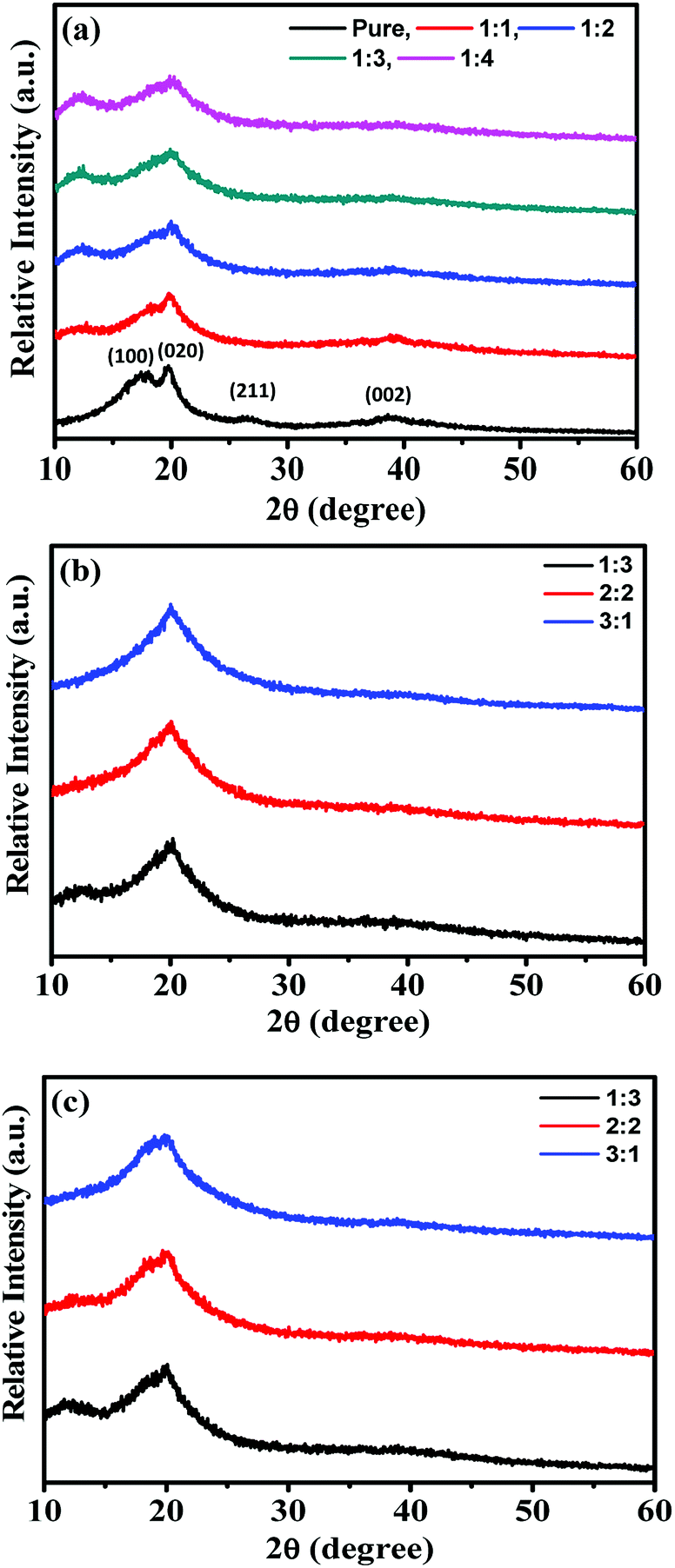
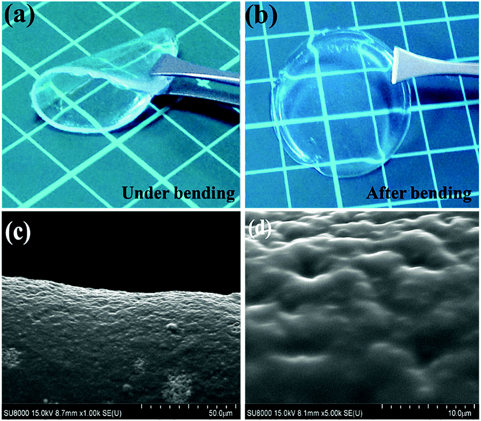
The flexible and highly conductive solid-like gel electrolytes were successfully fabricated using the solution casting method. The crystallinity was observed through the XRD spectra shown in Fig. 1. Fig. 1(a)–(c) show the XRD patterns of PVDF-HFP/BMIMTFSI, PVDF-HFP/BMIMTFSI/PC, and PVDF-HFP/BMIMTFSI/EC electrolytes, respectively. The pure PVDF-HFP film exhibited crystalline peaks at 18.07°, 19.81°, 26.15°, and 38.66°, as shown in Fig. 1(a), which were assigned to the (100), (020), (211), and (002) orientation planes, respectively.22,24,25 However, these peaks are broad and have low intensity, implying that PVDF-HFP has a semicrystalline nature.26–30 The values of full width at half maximum (FWHM) of the peak at 19.81° were 6.76°, 9.66°, 12.37°, 13.53°, and 14.41° at PVDF-HFP:BMIMTFSI ratios of 1:0 (pure PVDF-HFP), 1:1, 1:2, 1:3, and 1:4, respectively. When the BMIMTFSI was added into the PVDF-HFP polymer solution, the intensity of the XRD peaks decreased with an increase in BMIMTFSI concentration, as indicated in Fig. 1(a). Furthermore, the crystalline peaks of PVDF-HFP at 19.81° became broader. This phenomenon implies that BMIMTFSI can act as a plasticizer that increases the amorphicity of the film. In addition, such amorphous parts are beneficial for the ion-hopping mechanism, and consequently, for the ionic conductivity of the film.26–30 The BMIMTFSI content influences the ionic conductivity and strength of the electrolyte. The XRD patterns in Fig. 1(a) show a peak near 12.40° in all the PVDF-HFP/BMIMTFSI films, which may be induced by the interlayer formed between the polymer membrane and glass dish.31–34 The XRD patterns in Fig. 1(b) and (c) reveal that the peak at 12.40° became weaker or disappeared when the organic solvent was added in both cases. Clearly, the interlayer could not be formed with the organic solvent. Values of FWHM of the peak at 19.81° shown in Fig. 1(b) and (c) are (11.79°, 10.22°), (12.76°, 11.50°), and (14.45°, 12.81°) at BMIMTFSI:PC and BMIMTFSI:EC ratios of 3:1, 2:2, and 1:3, respectively. The crystalline peak at 19.81° becomes weaker and broader with an increase in the organic solvent, PC, or EC in both cases. This indicates that the organic solvent could also act as a plasticizer to reduce the crystallinity of electrolyte films35,36 because PC and EC are favorable solvents for PVDF-HFP polymer. The freestanding solid-like gel electrolyte film comprising PVDF-HFP, BMIMTFSI, and EC is shown in Fig. 2(a) and (b). The thickness of the film was approximately 436 μm, as measured by an electronic screw micrometer. The maintenance of the flexibility and shape of the film is demonstrated in Fig. 2(a) and (b), respectively. The microstructure of the film can be observed from SEM surface images (Fig. 2(c) and (d)), which reveal the morphology of the PVDF-HFP/BMIMTFSI/EC electrolyte film at different magnification scales. The film exhibits an island-like structure, which enables the ions to pass between the polymer islands. The slightly inhomogeneous surface indicates the nonuniform distribution of PVDF-HFP, BMIMTFSI, and EC because of different compatibilities between them.
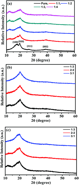 |
| | Fig. 1 XRD patterns of (a) PVDF-HFP/BMIMTFSI film with PVDF-HFP:BMIMTFSI ratios from 1:0 (pure PVDF-HFP) to 1:4, (b) PVDF-HFP/BMIMTFSI/PC film with BMIMTFSI:PC ratios from 3:1 to 1:3, and (c) PVDF-HFP/BMIMTFSI/EC film with ratios of BMIMTFSI:EC from 3:1 to 1:3. | |
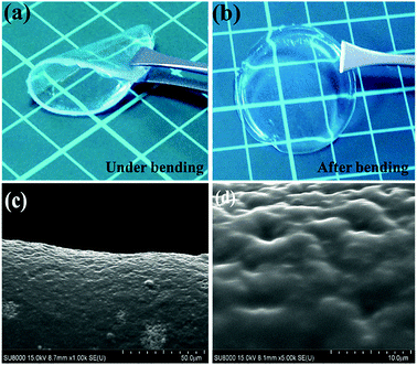 |
| | Fig. 2 Appearances (a) under and (b) after bending and (c and d) SEM surface images of the PVDF-HFP/BMIMTFSI/EC film with different magnification scales. | |
Electrochemical analysis of solid-like gel electrolytes
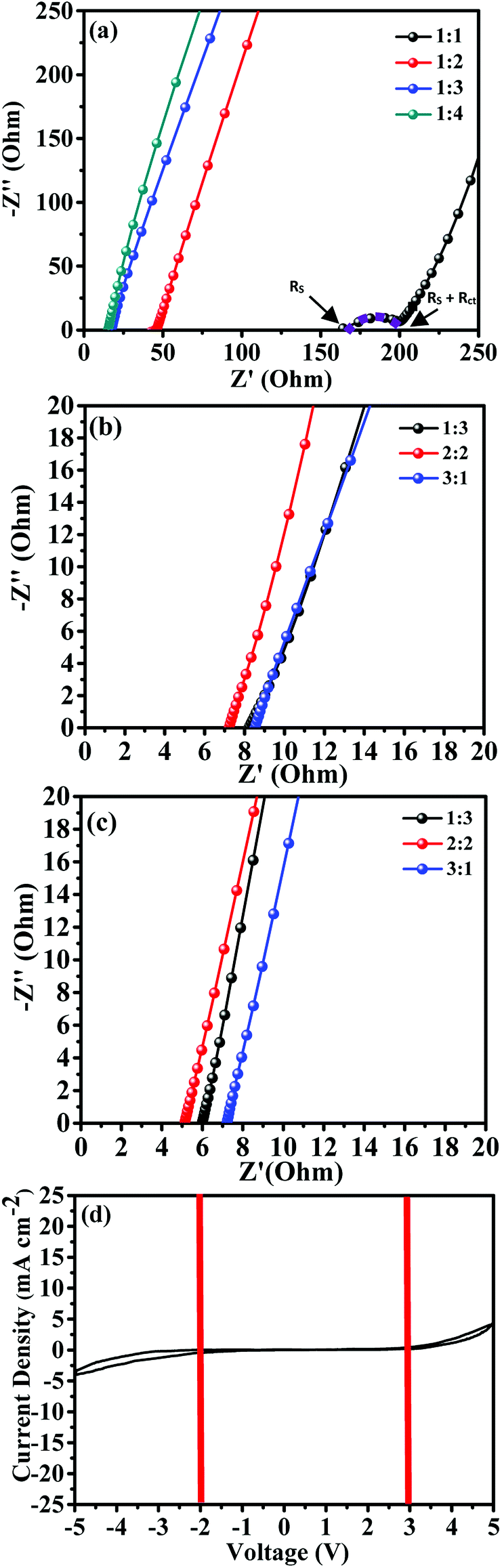
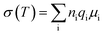
The electrical properties of the electrolyte films are shown in Fig. 3. Fig. 3(a)–(c) depict the Nyquist impedance plots of the PVDF-HFP/BMIMTFSI, PVDF-HFP/BMIMTFSI/PC, and PVDF-HFP/BMIMTFSI/EC electrolyte films, respectively. Fig. 3(d) shows the CV curve of PVDF-HFP/BMIMTFSI/EC to measure its operating voltage window at a scan rate of 10 mV s−1. Fig. 3(a) demonstrates the Nyquist impedance plots with various PVDF-HFP:BMIMTFSI ratios, indicating that the total resistance values (Rs + Rct) were 208.80, 45.78, 17.43, and 15.31 Ω for the 1:1, 1:2, 1:3, and 1:4 ratios, respectively. Rs is the solution resistance and Rct is the charge-transfer resistance. Conductivities calculated using eqn (1) were 0.25, 0.92, 2.51, and 2.74 mS cm−1 for the films with ratios of 1:1, 1:2, 1:3, and 1:4, respectively. As the BMIMTFSI weight ratio increased, the charge-transfer resistance decreased to nearly zero. Moreover, the semicircle in the plot disappears; this semicircle indicates that a transfer resistance of polymers existed when the ions move in the polymer matrix. The reason of improving conductivities is that BMIMTFSI is the ion source, which contributed to the conduction of devices, and the PVDF-HFP polymer is an insulator but provides mechanical strength to maintain the shape of the film. The higher the ratio of the BMIMTFSI, the higher is the ionic conductivity and the lower is the charge-transfer resistance of the films. Therefore, the semicircle disappears. Further raising the concentration of the BMIMTFSI, the film becomes soft gel. It is difficult to maintain its mechanical strength and shape. Thus, the 1:4 ratio of PVDF-HFP to BMIMTFSI is optimal according to these conductivity-based experimental data. To improve the conductivity further, two types of organic solvents (PC and EC) were used in this study with different ratios of BMIMTFSI to organic solvents. For maintaining the strength of the film, the ratio of PVDF-HFP to BMIMTFSI/PC or BMIMTFSI/EC was fixed at 1:4, and different weight ratios BMIMTFSI:PC and BMIMTFSI:EC of 1:3, 2:2, and 3:1 were studied. For the PVDF-HFP/BMIMTFSI/PC solid-like gel electrolyte, the series resistances shown in Fig. 3(b) are 8.27, 7.23, and 8.51 Ω for the 1:3, 2:2, and 3:1 films, respectively; that is, the conductivities are 4.66, 6.31, and 4.7 mS cm−1, respectively. For the PVDF-HFP/BMIMTFSI/EC solid-like gel electrolyte, the series resistances shown in Fig. 3(c) and resistances (conductivities) are 6.01 (8.26), 5.12 (8.52), and 7.21 Ω (6.30 mS cm−1) for the 1:3, 2:2, and 3:1 films, respectively. The conductivities improved because PC and EC have a high dielectric constant (much polar), which facilitates ions separation and increases the mobility (μ) of the ions, thereby increasing the conductivity.37,38 However, the 1:3 film exhibited a low number of ions per volume (n), resulting in a decrease in the ionic conductivity. Therefore, the 2:2 film has the best conductivity among all the aforementioned films. Compared with PC (63.9), EC exhibits a higher dielectric constant (92.8);39 thus, the performance of PVDF-HFP/BMIMTFSI/EC solid-like gel electrolyte is better than that of PVDF-HFP/BMIMTFSI/PC. Fig. 3(d) shows the CV of the PVDF-HFP/BMIMTFSI/EC gel electrolyte (the weight ratio of PVDF-HFP:BMIMTFSI:EC is 1:2:2.) measured at the scan rate of 10 mV s−1. The operation voltage obtained is from −2 V to +3 V, as indicated in Fig. 3(d). In summary, the PVDF-HFP/BMIMTFSI/EC electrolyte exhibited the maximum ionic conductivity of 8.52 mS cm−1 at a ratio of 1:2:2, and it possessed a wide 5 V operation voltage window of −2 to +3 V. From previous reports,2–21 the electrical conductivity ranges for the solid-state and gel-state electrolytes are 10−6 to 100 and 10−2 to 101 mS cm−1, respectively. The conductivity value of our solid-like gel electrolyte was close to those of reported gel-state electrolytes, but much higher than those of reported SPEs and close to the value of the pure BMIMTFSI (8.4 mS cm−1) electrolyte. Table 1 compares the conductivities obtained in this study and those of published data. The ionic conductivity for our electrolytes demonstrated considerable improvement. To realize the parameters related to conduction, the equation of electrical conductivity is given as| |
 | (6) |
where σ is the conductivity, T temperature, ni the number of the ion i per volume, qi the charge of the ion i, and μi is the mobility of ion i. As ni and μi increase, the conductivity increases.
 |
| | Fig. 3 Nyquist plots of (a) PVDF-HFP/BMIMTFSI film at PVDF-HFP:BMIMTFSI ratios from 1:0 (pure PVDF-HFP) to 1:4, (b) PVDF-HFP/BMIMTFSI/PC film with BMIMTFSI:PC ratios from 1:3 to 3:1, and (c) PVDF-HFP/BMIMTFSI/EC film with BMIMTFSI:EC ratios from 1:3 to 3:1. (d) CV curve of the PVDF-HFP/BMIMTFSI/EC electrolyte film at scan rate of 10 mV s−1. | |
Table 1 Comparison of the conductivities at room temperature between this study and review papers
| Type of electrolytes |
Compositions of electrolytes |
Conductivity (mS cm−1) |
Reference |
| Solid-like |
PVDF-HFP/BMIMTFSI |
2.74 |
This work |
| Solid-like |
PVDF-HFP/BMIMTFSI/EC |
8.52 |
This work |
| Solid-like |
PVDF-HFP/BMIMTFSI/EC/LiClO4 |
8.18 |
This work |
| Pure liquid |
BMIMTFSI |
8.4 |
40 |
| Solid-state |
PEO-PMMA-LiClO4-15 wt% PA |
1.59 × 10⁻² |
41 |
| Solid-state |
Jeffamine-based SPEs |
4.5 × 10⁻² |
42 |
| Solid-state |
PEGBCDA/SCN/LiTFSI |
∼1 |
43 |
| Solid-state |
1 M LiPF6-PC/F-EPE/FEC (60:30:10) |
5.04 |
44 |
| Solid-state |
Perfluorinated sulfonic acid polymer |
0.15 |
45 |
| Solid-state |
PEO, PPO, PVAc-Li or Na salt-with/without solvent |
10−4–1 |
9 |
| Gel-state |
Iodide based-LDH-St-5 wt% |
1.79 |
44 |
| Gel-state |
PVdF-HFP/BMIMTFSI/LiTFSI |
2 |
45 |
| Gel-state |
11PAN-12NaClO4-40EC-37PC |
4.5 |
46 |
| Gel-state |
PAN-LiClO4 with EC, PC, DMF… |
0.4–4 |
9 |
| Gel-state |
PMMA or PVA or PMMA-EC/PC-Li salt |
1–6 |
9 |
| Gel-state |
PVdF-HFP-MPII-PC/DME |
1.05 × 10⁻² |
47 |
| Gel-state |
PVdF-HFP/EC/PC/NaCF3SO3 |
2.5 |
48 |
| Gel-state |
PAN/EC/PC with iodide salt |
2 |
49 |
| Gel-state |
PMMA/EC:PC with magnesium salt |
2.43–6.08 |
50 |
| Gel-state |
PLA-EC with LiClO4 |
1.29 × 10⁻² |
51 |
| Gel-state |
PVDH-HFP/LiTFSI/LATP |
2.1 |
52 |
| Gel-state |
EC + DEC + TFEP + LiPF6 |
4.8 |
53 |
| Gel-state |
Ionic liquid-based PEO electrolytes with Li salt |
1.6 |
54 |
| Gel-state |
PVDF-HFP/EC/DEC with lithium salt |
1.06 |
55 |
| Gel-state |
PVdF-HFP-PEMA/PC with lithium salt |
3.17 |
56 |
| Gel-state |
PAN/EC/PC with sodium salt |
4.5 |
57 |
| Gel-state |
PVDF-HFP:LiBF4:EC |
1.66 |
58 |
| Gel-state |
HPC:EC:PC:NaI:MPII |
7.37 |
59 |
The ionic mobility of the liquid-state electrolyte is much larger than those of the gel-state and SSE, and the ionic mobility of the gel-state electrolyte is higher than that of the solid-state one.
Therefore, the mixture of polymer, IL and organic solvent (solid-like gel electrolyte) in this study exhibited very high conductivity.
This flexible solid-like electrolyte with ultrahigh ionic conductivity has high potential for using in energy storage, conversion, and wearable devices.
Electrochemical analysis of asymmetrical supercapacitors
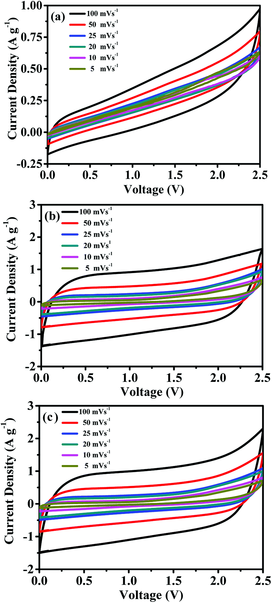
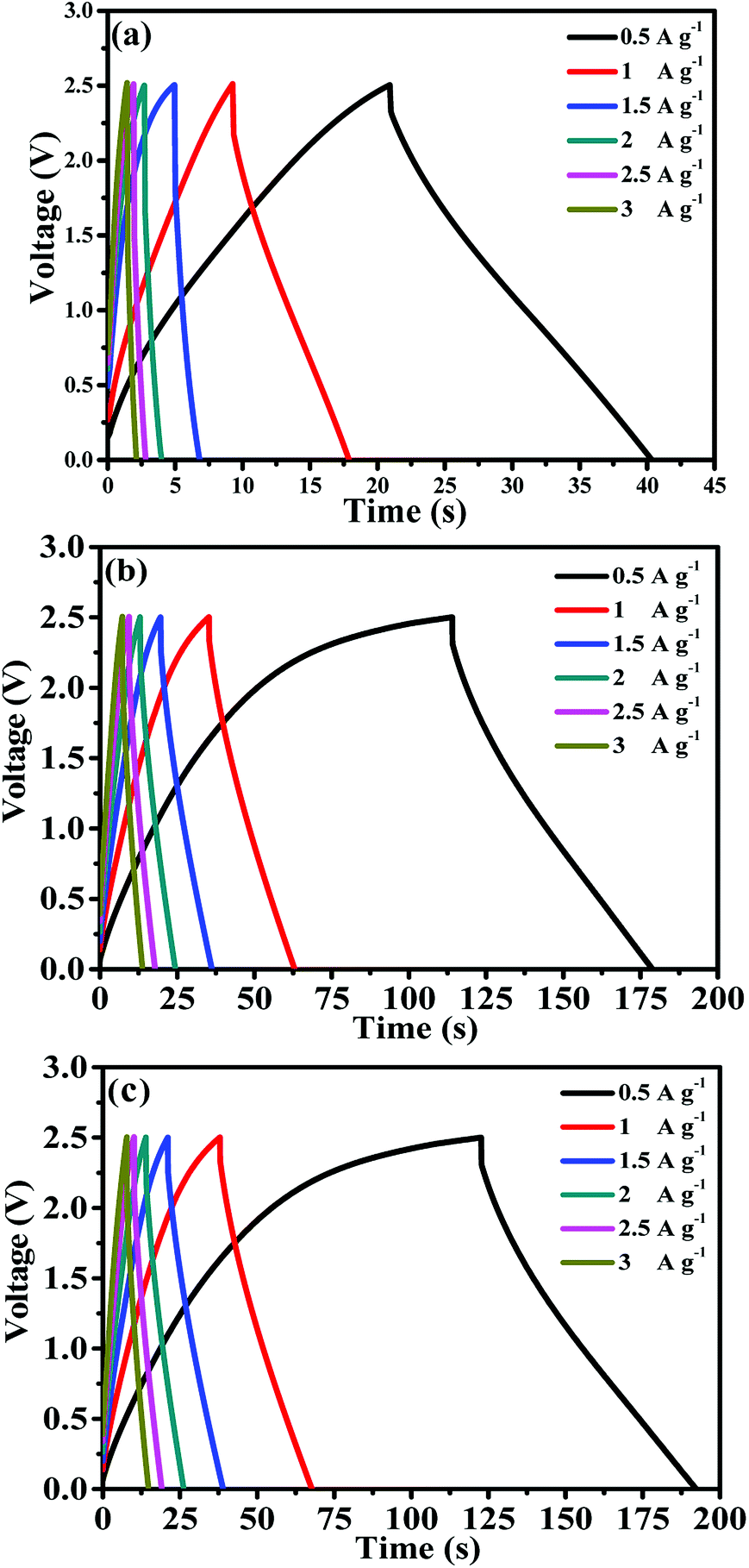
Using the aforementioned electrolytes, symmetrical supercapacitors were fabricated and their electrochemical properties were analyzed. The carbon-containing electrodes were used as both anode and cathode. These electrodes comprised AC, MWCNTs, and PVDF with a weight ratio of 65:20:15. AC provides a high surface area, thereby increasing the electric double-layer capacitance. The MWCNTs possess a highly electrolyte accessible network to form the AC/CNT 3D network. The PVDF is a binder that improves the adhesion property. Fig. 4 shows the nitrogen adsorption and desorption isotherms of the mixture of AC and MWCNTs. The specific surface area of the mixture is 508.82 m2 g−1. The high specific surface area provides large amount of adsorption sites for electrolytes to improve the capacitance of supercapacitors. The pore diameter distributes from 1 to 120 nm, and most of the pore diameter range between 20 and 80 nm. A small amount of pore diameter is below 2 nm. The fabrication process was described in the experimental section. Fig. 5 depicts the CV curves of the symmetrical supercapacitor with (a) the PVDF-HFP/BMIMTFSI electrolyte and (b) the PVDF-HFP/BMIMTFSI/EC electrolyte at various scan rates of 5–100 mV s−1. To apply to lithium batteries, lithium salt (LiClO4) was added to produce the PVDF-HFP/BMIMTFSI/EC/LiClO4 solid-like electrolyte. The detailed manufacturing procedure is presented in the experimental section. The CV curve of the PVDF-HFP/BMIMTFSI/EC/LiClO4 solid-like electrolyte is shown in Fig. 5(c). A comparison between the CV curves (Fig. 5(a)–(c)) of the PVDF-HFP/BMIMTFSI, PVDF-HFP/BMIMTFSI/EC, and PVDF-HFP/BMIMTFSI/EC/LiClO4 electrolytes reveals a rectangle-like shape for all the electrolytes. However, the CV curve of the PVDF-HFP/BMIMTFSI electrolyte is oblique, indicating that there is a large resistance that consumes energy and converts it into heat. Moreover, the CV curve of the PVDF-HFP/BMIMTFSI/EC electrolyte is more rectangular than that of the PVDF-HFP/BMIMTFSI/EC/LiClO4 electrolyte near the high voltage region (2–2.5 V). This is because the LiClO4 is an active chemical agent with many side reactions. The PVDF-HFP/BMIMTFSI/EC electrolyte is more stable than that of the PVDF-HFP/BMIMTFSI/EC/LiClO4 electrolyte. Fig. 6 shows GCD curves of the symmetrical supercapacitor with (a) the PVDF-HFP/BMIMTFSI electrolyte, (b) the PVDF-HFP/BMIMTFSI/EC electrolyte, and (c) the PVDF-HFP/BMIMTFSI/EC/LiClO4 electrolyte at various current densities from 0.5 to 3 A g−1. The specific capacitances of the electrolytes are calculated based on Fig. 6, eqn (2) and (3), and the results are shown in Fig. 7. The specific capacitance was 16.4, 72, and 78.8 F g−1 at a current density of 0.5 A g−1, and 5, 31.2, and 35.5 F g−1 at a current density of 3 A g−1 for the PVDF-HFEP/BMIMTFSI, PVDF-HFEP/BMIMTFSI/EC, and PVDF-HFP/BMIMTFSI/EC/LiClO4 electrolytes, respectively. The capacitance of the PVDF-HFP/BMIMTFSI/EC/LiClO4 electrolyte was the highest among all electrolytes. This phenomenon is because the inner pore sizes of the AC were small (0.1–2.5 nm (ref. 60)), and therefore the IL ions are difficult to transfer to the electrode inner pore structure because of their larger ionic size. However, the hydrated radius of the Li ions in the LiClO4 salt is very small, and the hydrated radius of the IL is usually larger than that of the salt. Hence, the IL ions move only on the surface of the AC; however, the Li ions move not only on the surface but also into the inner pores. Therefore, adding lithium salt increases the number of adsorption ions, thus enhancing the capacitance. LiClO4 is the electrolyte of Li-ion batteries. The solid-like electrolytes of this study can be applied to both Li-ion batteries and supercapacitors.
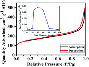 |
| | Fig. 4 Nitrogen adsorption and desorption isotherms for the mixture of AC and MWCNTs. The inset is the corresponding pore size distribution. | |
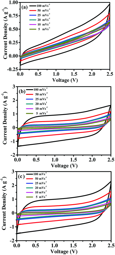 |
| | Fig. 5 CV curves of the symmetrical supercapacitor with (a) the PVDF-HFP/BMIMTFSI electrolyte, (b) the PVDF-HFP/BMIMTFSI/EC electrolyte, and (c) the PVDF-HFP/BMIMTFSI/EC/LiClO4 electrolyte. | |
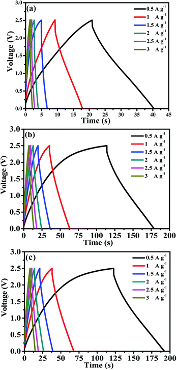 |
| | Fig. 6 GCD curves of symmetrical supercapacitors with (a) the PVDF-HFP/BMIMTFSI electrolyte, (b) the PVDF-HFP/BMIMTFSI/EC electrolyte, and (c) the PVDF-HFP/BMIMTFSI/EC/LiClO4 electrolyte. | |
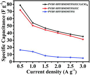 |
| | Fig. 7 Capacitance curves of the symmetric supercapacitors with the PVDF-HFP/BMIMTFSI electrolyte, the PVDF-HFP/BMIMTFSI/EC electrolyte, and the PVDF-HFP/BMIMTFSI/EC/LiClO4 electrolyte with current densities from 0.5 to 3 A g−1. | |
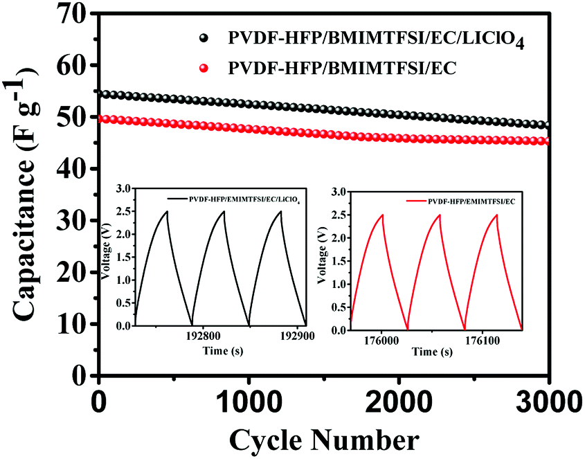
Fig. 8 illustrates the Nyquist impedance plots of symmetrical supercapacitors with the PVDF-HFP/BMIMTFSI, PVDF-HFEP/BMIMTFSI/EC, and PVDF-HFP/BMIMTFSI/EC/LiClO4 electrolytes, indicating that the series resistances (conductivities) were 6.98 Ω (6.73 mS cm−1), 5.33 Ω (8.44 mS cm−1), and 5.57 Ω (8.18 mS cm−1), respectively. Although the difference between the conductivities of the PVDF-HFP/BMIMTFSI and PVDF-HFEP/BMIMTFSI/EC was only 1.71 mS cm−1, the capacitance of the PVDF-HFP/BMIMTFSI/EC (72 F g−1) was 4.4 times that of the PVDF-HFP/BMIMTFSI (16.4 F g−1) at a current density of 0.5 A g−1. Conductivities of solid-like electrolyte are critical for improving the electrochemical properties. The supercapacitor with the PVDF-HFP/BMIMTFSI electrolyte wasted higher energy compared with another system due to higher internal resistance. On the basis of eqn (4) and (5), this flexible and all-solid-state supercapacitor exhibited a maximum power density of 747 W kg−1 at an energy density of 7.71 W h kg−1 and a maximum energy density of 17.1 W h kg−1 at an energy density of 630 W kg−1. It also displays excellent cycling stabilities with 88.9% and 91.3% of the initial specific capacitance after 3000 charging/discharging cycles for the symmetrical supercapacitors using PVDF-HFP/BMIMTFSI/EC/LiClO4 and PVDF-HFP/BMIMTFSI/EC solid-like electrolytes, respectively, as shown in Fig. 9.
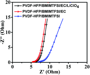 |
| | Fig. 8 EIS curves of the symmetric supercapacitor with the PVDF-HFP/BMIMTFSI electrolyte, the PVDF-HFP/BMIMTFSI/EC electrolyte, and the PVDF-HFP/BMIMTFSI/EC/LiClO4 electrolyte. | |
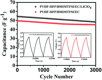 |
| | Fig. 9 The cycling stability of the symmetrical supercapacitors. The drawings in the insets are last three charging/discharging GCD curves of the symmetrical supercapacitors using PVDF-HFP/BMIMTFSI/EC/LiClO4 and PVDF-HFP/BMIMTFSI/EC solid-like electrolytes, respectively. | |
Conclusions
A high quality solid-like gel electrolyte sample was synthesized through the solution casting approach. The XRD and SEM analyses verified the morphology and the crystallinity of the solid-like gel electrolyte films. Crystallinity has been observed to influence the ionic conductivity performance. The amorphous part in films benefits the ion transfer process. The conductivity was optimized with the PVDF-HFP:BMIMTFSI:EC weight ratio of 1:2:2. The high dielectric constant of the organic solvent (EC or PC) could help ion pairs separate easily and improved the mobility of BMIMTFSI. The maximum conductivity was 8.52 mS cm−1, and the operating voltage window was 5 V (−2 to +3 V).
This solid-like polymer matrix film prevents the upper and lower electrodes from contacting by working as a separator. The review conducted by Ngai et al.10 revealed that the highest ionic conductivity of PVDF-HFP electrolyte complexes achieved at ambient temperature was 4.3 mS cm−1. The value obtained in this work was higher than this value and those of most of solid and gel electrolytes. It was also higher than the value obtained for the pure IL BMIMTFSI (8.4 mS cm−1). This film was not only an electrolyte but also a separator with high conductivity and wide operating voltage window.
Using AC, MWCNTs, and PVDF as both the anode and cathode with a solid-state electrolyte, a symmetrical supercapacitor was fabricated that exhibited a maximum power density of 747 W kg−1 at an energy density of 7.71 W h kg−1 and a maximum energy density of 17.1 W h kg−1 at an energy density of 630 W kg−1. It also exhibited excellent cycling stabilities with 88.9% and 91.3% of the initial specific capacitance after 3000 cycles for the symmetrical supercapacitors using PVDF-HFP/BMIMTFSI/EC/LiClO4 and PVDF-HFP/BMIMTFSI/EC solid-like electrolytes, respectively. The flexible and ultrahigh conductivity solid-state electrolyte in this study has high potential for use in energy storage, conversion, and wearable device applications.
Conflicts of interest
There are no conflicts to declare.
Acknowledgements
This work was supported by the Ministry of Science and Technology under contract No. 106-2221-E-009-077.
References
- A. Mauger, M. Armand, C. M. Julien and K. Zaghib, J. Power Sources, 2017, 353, 333–342 CrossRef.
- A. Manuel Stephan and K. S. Nahm, Polymer, 2006, 47, 5952–5964 CrossRef.
- O. A. Ileperuma, Mater. Technol., 2013, 28, 65–70 CrossRef.
- C. A. Angell, Electrochim. Acta, 2017, 250, 368–375 CrossRef.
- L. Yue, J. Ma, J. Zhang, J. Zhao, S. Dong, Z. Liu, G. Cui and L. Chen, Energy Storage Materials, 2016, 5, 139–164 CrossRef.
- R. Sood, S. Cavaliere, D. J. Jones and J. Rozière, Nano Energy, 2016, 26, 729–745 CrossRef.
- D. Golodnitsky, E. Strauss, E. Peled and S. Greenbaum, J. Electrochem. Soc., 2015, 162, A2551–A2566 CrossRef.
- L. Long, S. Wang, M. Xiao and Y. Meng, J. Mater. Chem. A, 2016, 4, 10038–10069 RSC.
- R. C. Agrawal and G. P. Pandey, J. Phys. D: Appl. Phys., 2008, 41, 223001 CrossRef.
- K. S. Ngai, S. Ramesh, K. Ramesh and J. C. Juan, Ionics, 2016, 22, 1259–1279 CrossRef.
- R. He and T. Kyu, Macromolecules, 2016, 49, 5637–5648 CrossRef.
- C. C. Yang, S. T. Hsu and W. C. Chien, J. Power Sources, 2005, 152, 303–310 CrossRef.
- G. Ma, J. Li, K. Sun, H. Peng, J. Mu and Z. Lei, J. Power Sources, 2014, 256, 281–287 CrossRef.
- G. P. Pandey, A. C. Rastogi and C. R. Westgate, ECS Trans., 2013, 50, 145–151 CrossRef.
- P. Sivaraman, A. Thakur, R. K. Kushwaha, D. Ratna and A. B. Samui, Electrochem. Solid-State Lett., 2006, 9, A435–A438 CrossRef.
- G. P. Pandey and S. A. Hashmi, J. Mater. Chem. A, 2013, 1, 3372–3378 RSC.
- M. Rosi, F. Iskandar, M. Abdullah and Khairurrijal, Int. J. Electrochem. Sci., 2014, 9, 4251–4256 Search PubMed.
- Z. Osman, K. B. M. Isa, A. Ahmad and L. Othman, Ionics, 2010, 16, 431–435 CrossRef.
- J. Zhou, J. Cai, S. Cai, X. Zhou and A. N. Mansour, J. Power Sources, 2011, 196, 10479–10483 CrossRef.
- N. Ataollahi, A. Ahmad, H. Hamzah, M. Y. A. Rahman and N. S. Mohamed, Int. J. Electrochem. Sci., 2012, 7, 6693–6703 Search PubMed.
- S. Ramesh and O. P. Ling, Polym. Chem., 2010, 1, 702–707 RSC.
- J. Tang, R. Muchakayala, S. Song, M. Wang and K. N. Kumar, Polym. Test., 2016, 50, 247–254 CrossRef.
- K. Yu Jin, C. Haegeun, H. Chi-Hwan and K. Woong, Nanotechnology, 2012, 23, 065401 CrossRef PubMed.
- S. Abbrent, J. Plestil, D. Hlavata, J. Lindgren and J. Tegenfeldt, Å. Wendsjö, Polymer, 2001, 42, 1407–1416 CrossRef.
- G. C. Li, P. Zhang, H. P. Zhang, L. C. Yang and Y. P. Wu, Electrochem. Commun., 2008, 10, 1883–1885 CrossRef.
- P. K. Singh, K. C. Sabin and X. Chen, Polym. Bull., 2015, 73, 255–263 CrossRef.
- Shalu, S. K. Chaurasia, R. K. Singh and S. Chandra, Thermal Stability, J. Phys. Chem. B, 2013, 117, 897–906 CrossRef PubMed.
- C. W. Liew, Y. S. Ong, J. Y. Lim, C. S. Lim, K. H. Teoh and S. Ramesh, Int. J. Electrochem. Sci., 2013, 8, 7779–7794 Search PubMed.
- Shalu, V. K. Singh and R. K. Singh, J. Mater. Chem. C, 2015, 3, 7305 RSC.
- Shalu, L. Balo, H. Gupta, V. K. Singh and R. K. Singh, RSC Adv., 2016, 6, 73028 RSC.
- P. Tamilarasan and S. Ramaprabhu, Energy, 2013, 51, 374–381 CrossRef.
- S. Bovio, A. Podestà, C. Lenardi and P. Milani, J. Phys. Chem. B, 2009, 113, 6600–6603 CrossRef PubMed.
- Y. Liu, Y. Zhang, G. Wu and J. Hu, J. Am. Chem. Soc., 2006, 128, 7456–7457 CrossRef PubMed.
- A. J. Carmichael, C. Hardacre, J. D. Holbrey, M. Nieuwenhuyzen and K. R. Seddon, Mol. Phys., 2001, 99, 795–800 CrossRef.
- S. Rajendran and P. Sivakumar, Phys. B, 2008, 403, 509–516 CrossRef.
- S. A. Mohamed, A. A. Al-Ghamdi, G. D. Sharma and M. K. El Mansy, J. Adv. Res., 2014, 5, 79–86 CrossRef PubMed.
- V. Ruiz, T. Huynh, S. R. Sivakkumar and A. G. Pandolfo, RSC Adv., 2012, 2, 5591–5598 RSC.
- R. A. Dileo, A. C. Marschilok, K. J. Takeuchi and E. S. Takeuchi, J. Electrochem. Soc., 2013, 160, A1399–A1405 CrossRef.
- M. S. Ding, Liquid Phase Boundaries, J. Electrochem. Soc., 2003, 150, A455–A462 CrossRef.
- M. C. Buzzeo, R. G. Evans and R. G. Compton, ChemPhysChem, 2004, 5, 1106–1120 CrossRef PubMed.
- B. Liang, Q. Jiang, S. Tang, S. Li and X. Chen, J. Power Sources, 2016, 307, 320–328 CrossRef.
- I. Aldalur, H. Zhang, M. Piszcz, U. Oteo, L. M. Rodriguez-Martinez, D. Shanmukaraj, T. Rojo and M. Armand, J. Power Sources, 2017, 347, 37–46 CrossRef.
- G. Fu, J. Dempsey, K. Izaki, K. Adachi, Y. Tsukahara and T. Kyu, J. Power Sources, 2017, 359, 441–449 CrossRef.
- P. Shi, S. Fang, D. Luo, L. Yang and S.-i. Hirano, J. Electrochem. Soc., 2017, 164, A1991–A1999 CrossRef.
- Y. Shi, C. Wu, L. Li and J. Yang, J. Electrochem. Soc., 2017, 164, A2031–A2037 CrossRef.
- K. Vignarooban, P. Badami, M. A. K. L. Dissanayake, P. Ravirajan and A. M. Kannan, Ionics, 2017, 23, 2817 CrossRef.
- F. Saaid, L. Rodi and T. Winie, AIP Conf. Proc., 2017, 1877, 020006 CrossRef.
- K. B. Md Isa, L. Othman, D. Hambali and Z. Osman, AIP Conf. Proc., 2017, 1877, 040001 CrossRef.
- T. M. W. J. Bandara, T. Svensson, M. A. K. L. Dissanayake, M. Furlani, W. J. M. J. S. R. Jayasundara, P. S. L. Fernando, I. Albinsson and B. E. Mellander, J. Natl. Sci. Found. Sri Lanka, 2013, 41(3), 175–184 CrossRef.
- N. H. Zainol, S. M. Samin, L. Othman, K. B. Md Isa, W. G. Chong and Z. Osman, Int. J. Electrochem. Sci., 2013, 8, 3602–3614 Search PubMed.
- K. W. Chew, T. C. Ng and Z. H. How, Int. J. Electrochem. Sci., 2013, 8, 6354–6364 Search PubMed.
- N. Aliahmad, S. Shrestha, K. Varahramyan and M. Agarwal, AIP Adv., 2016, 6, 065206 CrossRef.
- T. Hazama, K. Fujii, T. Sakai, M. Aoki, H. Mimura, H. Eguchi, Y. Todorov, N. Yoshimoto and M. Morita, J. Power Sources, 2015, 286, 470–474 CrossRef.
- E. Simonetti, M. Carewska, G. Maresca, M. De Francesco and G. B. Appetecchia, J. Electrochem. Soc., 2017, 164(1), A6213–A6219 CrossRef.
- W. Liu, X. K. Zhang, F. Wu and Y. Xiang, IOP Conf. Ser.: Mater. Sci. Eng., 2017, 213, 012036 Search PubMed.
- R. M. Ubarhande, S. Bhattacharya, M. U. Rani, R. S. Babu and S. Krishnaveni, IOP Conf. Ser.: Mater. Sci. Eng., 2017, 263, 022004 Search PubMed.
- K. Vignarooban, P. Badami, M. A. K. L. Dissanayake, P. Ravirajan and A. M. Kannan, Ionics, 2017, 23, 2817 CrossRef.
- M. Sangeetha, A. Mallikarjun, M. J. Reddy and J. S. Kumar, IOP Conf. Ser.: Mater. Sci. Eng., 2017, 225, 012049 Search PubMed.
- M. H. Khanmirzaei, S. Ramesh and K. Ramesh, Sci. Rep., 2015, 5, 18056 CrossRef PubMed.
- R. Kaiser, A. Kulczyk, D. Rich, R. J. Willey, J. Minicucci and B. MacIver, Ind. Eng. Chem. Res., 2007, 46, 6126–6132 CrossRef.
|
| This journal is © The Royal Society of Chemistry 2018 |
Click here to see how this site uses Cookies. View our privacy policy here. 
 Open Access Article
 This Open Access Article is licensed under a Creative Commons Attribution-Non Commercial 3.0 Unported Licence
 a,
Hao-Yang Lina,
Amit Kumara,
Bhaskar Pattanayaka,
Hung-Yi Tsaia,
Tan Winieb and
Tseung-Yuen Tseng
a,
Hao-Yang Lina,
Amit Kumara,
Bhaskar Pattanayaka,
Hung-Yi Tsaia,
Tan Winieb and
Tseung-Yuen Tseng