 Open Access Article
Earth-abundant and environment friendly organic–inorganic hybrid tetrachloroferrate salt CH3NH3FeCl4: structure, adsorption properties and photoelectric behavior†
Jie Yin*,
Shaozhen Shi,
Jiazhen Wei,
Guohang He,
Lin Fan,
Junxue Guo,
Kaixuan Zhang,
Wenli Xu,
Cang Yuan,
Yunying Wang,
Liwen Wang,
Xipeng Pu ,
Wenzhi Li,
Dafeng Zhang,
Jie Wang,
Xiaozhen Ren,
Huiyan Ma,
Xin Shao and
Huawei Zhou
 *
*
College of Materials Science and Engineering, Liaocheng University; School of Chemistry and Chemical Engineering, Liaocheng University, Shandong Provincial Key Laboratory of Chemical Energy Storage and Novel Cell Technology, Liaocheng 252059, China. E-mail: yinjieily@163.com; zhouhuaweiopv@163.com
First published on 30th May 2018
Abstract
Organic–inorganic hybrid-based lead perovskites show inherent and unavoidable problems such as structural instability and toxicity. Therefore, developing low-cost and environment-friendly organic–inorganic hybrid materials is extremely urgent. In this study, we prepared earth-abundant and environment-friendly organic–inorganic hybrid tetrachloroferrate salt CH3NH3FeCl4 (MAFeCl4) for optoelectronic applications. The single crystal diffraction data are assigned to the orthorhombic MAFeCl4 (Pnma space group), with parameters a = 11.453 (5) Å, b = 7.332 (3) Å, c = 10.107 (5) Å, α = 90.000, β = 90.000, and γ = 90.000. The band gap of MAFeCl4 is approximately 2.15 eV. Moreover, three-emission luminescence (398, 432 and 664 nm) was observed. To the best of our knowledge, this is the first study involving the investigation of the structure, adsorption properties and photoelectric behavior of MAFeCl4. A low cost photodetector based on the MAFeCl4 thin film is efficient under different monochromatic light from 330 nm to 410 nm with different chopping frequencies (1.33 Hz to 40 Hz). The photoelectric conversion efficiency based on FTO/TiO2/MAFeCl4/carbon electrode device reaches 0.054% (Voc = 319 mV, Jsc = 0.375 mA cm−2, and fill factor = 0.45) under AM1.5, 100 mW cm−2 simulated illumination. Our findings will attract attention from the magnetic, piezoelectric and photoelectronic research fields.
Introduction
As one type of organic–inorganic hybrid material (OIHM), organic–inorganic hybrid perovskite (OIHP) has received widespread attention in the scientific community and in the industrial world. Among OIHPs, organic–inorganic hybrid lead perovskite exhibits very advantageous performances in photovoltaics,1, lasers,2 photodetectors3 and so on. Recently, it has been reported that the power conversion efficiency (PCE) of solid thin film solar cells using organic-inorganic hybrid lead perovskite as a light absorbing material is up to 22%,4 suggesting that they could become promising commercial solar cells. In addition, the preparation of perovskite by solvothermal methods greatly reduces the cost of mass production. It is well known that a high-quality photoelectric device not only requires high performance and low cost, but also should have good stability and be environmentally friendly. However, there are some unavoidable problems in organic–inorganic hybrid lead perovskites. On the one hand, the cost of lead halide is high. On the other hand, the toxicity of lead in organic–inorganic hybrid lead perovskites is troubling.5 Therefore, developing low-cost and environment-friendly organic–inorganic hybrid materials is extremely urgent. Recently, Pb-free and IVA-metal (Tin or Germanium)-based OIHPs have been studied. Organic-inorganic hybrid tin materials were synthesized using different halide sources to directly synthesize the nanostructure or by applying a postsynthetic anion exchange reaction.6 Organic–inorganic hybrid germanium materials, AGeI3 (A = Cs, organic cation), with second harmonic generation (SHG) properties were synthesized by replacing the inorganic cation in the A position of the perovskite unit.7 Non-IVA-metal [single metal(+2) or mixed metal(+1, +3)]-based OIHP have also been developed. The organic–inorganic hybrid double-perovskite structure material Cs2AgBiBr6 with a long room-temperature fundamental photoluminescence (PL) lifetime was formed by incorporating nontoxic Bi3+ into the perovskite lattice.8 Layered (CH3NH3)2MnCl4 (MA2MnCl4) and amorphous manganese MAMnI3 were exploited for optoelectronic applications.9,10 A lead-free highly stable C6H4NH2CuBr2I compound that exhibits extraordinary hydrophobic behaviour was developed.11 However, the efficiency and cost of the abovementioned materials are not ideal, and the stability is not very good.Therefore, it is very necessary to develop new types of low-cost and environment-friendly organic–inorganic hybrid materials. In this study, we prepared CH3NH3FeCl4 (MAFeCl4) single crystals and films (see Experiment section). The crystal structure, luminescence, band gap, adsorption properties and photoelectric behavior were studied.
Experimental
Preparation of CH3NH3FeCl4 single crystal
162.5 mg FeCl3 and 67.5 mg CH3NH3Cl were added to a mixed solvent (3 mL methanol, 3 mL ethanol and 2 mL 35–36% HCl). The above solution was heated to 80 °C for 2 h. Then, the temperature was reduced to 40 °C over 20 h, following which a yellow-brown single crystal was obtained.Single crystal X-ray diffraction (XRD) characterization
Data were collected on a Bruker SMART CCD diffractometer using Mo Kα radiation (λ = 0.71073 Å). The structures were solved by direct methods and expanded via difference Fourier techniques with the SHELXL-97 program.Preparation of the CH3NH3FeCl4 optoelectronic device
Patterned FTO-coated glass substrates with sheet resistances of 15 Ω sq−1 were coated with a TiO2 compact layer by spin-coating the TiO2 organic sol at 3000 rpm for 30 s, followed by drying at 450 °C for 30 min following our previous literature report.9,10 The MAFeCl4 layer was prepared by spin coating 162.5 mg of FeCl3 and 67.5 mg of the CH3NH3Cl mixed precursor at 3000 rpm for 30 s, followed by gradual heating to 70 °C; the layer was baked at this temperature for 30 min. Finally, the carbon electrodes were prepared following our previous literature protocol;9,10 the MAFeCl4 layer was coated with conductive-carbon paste by the doctor-blade method using adhesive tapes for creating patterns and spaces, followed by drying at 70 °C for 40 min. The size of the FTO/TiO2/MAFeCl4/carbon electrode device was 1 cm2.Characterization of the CH3NH3FeCl4 optoelectronic device
Nanostructures of MAFeCl4 films were characterized by scanning electron microscopy (SEM, Hitachi SEM S-4800). UV-vis absorption spectra and diffuse reflectance spectra were obtained using a UV-vis-NIR spectrometer (PerkinElmer, λ, 750S). The photocurrent–time performance of FTO/TiO2/MAFeCl4/carbon electrode devices was studied using an electrochemical workstation system (CHI760, Chenhua, and Shanghai) equipped with a solar simulator (IV5, PV Measurements, Inc., United States). The photocurrent–time with incident photon (wavelength) and frequency response was measured by an electrochemical workstation system (CHI760, Chenhua, and Shanghai) equipped with a quantum efficiency/spectral response (SR)/incident photon to current conversion efficiency (IPCE) measurement system (QEX10, PV Measurements, Inc., United States). The photocurrents of the devices were measured under a bias voltage of 0.00 V.Results and discussion
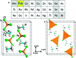
The color of the MAFeCl4 single crystal is yellow-brown. The single crystal structure was solved by a direct method and was extended using the SHELXL-97 program using differential Fourier technology. The single crystal diffraction data were assigned to the orthorhombic MAFeCl4 (Pnma space group), with parameters a = 11.453 (5) Å, b = 7.332 (3) Å, c = 10.107 (5) Å, α = 90.000, β = 90.000, and γ = 90.000. The schematic diagram of the unit cell structure is shown in Fig. 1. As seen from the projection down to the ac-plane (Fig. 1), tetrachloroferrate FeCl4− ions are distributed in the unit cell. Due to the four Cl ligands and the d5 of Fe3+, FeCl4− ions form regular tetrahedron structures. Thus, there should be a residual electron on the remaining d-orbit. MA+ is distributed around the FeCl4− ions. There is a relatively short hydrogen bond (NH⋯Cl, 2.797 Å) between the MA+ groups and the FeCl4− ions. Accordingly, the shortest Cl⋯Cl distances between the neighboring FeCl4− ions is 4.133 Å, which is much longer than the van der Waals distance (3.90 Å). These structural features suggest stronger s–d interactions between the FeCl4− ions and the MA+ groups. The detailed crystal data and structural refinement of the MAFeCl4 single crystal can be observed in Tables 1, 2, S1, and S2.† The structure of the MAFeCl4 single crystal is different from that of the classical perovskite structure (ABX3). First, the crystal structure of MAFeCl4 is no longer the perovskite structure. Second, the valence of Fe in MAFeCl4 is +3, which is different from that of Pb in MAPbI3. Third, the band gap of MAFeCl4 is different from that of MAPbI3. Thus, the performance of the MAFeCl4 single crystal is also different from that of the classic perovskite. | ||
| Fig. 1 (a) The position of iron in the periodic table of elements. (b and c) Schematic diagrams of the unit cell structure in ball-stick type and polyhedron type, respectively. | ||
| Compound | C·H6·Cl4·Fe·N |
|---|---|
| Chemical composition | CH3NH3FeCl4 |
| Crystal system | Orthorhombic |
| Space group, Z | Pnma |
| Temperature/K | 298(2) K |
| a, A | 11.453(5) |
| b, A | 7.332(3) |
| c, A | 10.107(5) |
| α, deg | 90 |
| β, deg | 90 |
| γ, deg | 90 |
| Volume, A3 | 848.7(7) |
| ρ, Mg m−3 | 4, 1.798 |
| μ, mm−1 | 2.939 |
| Total reflections, R(int) | 3945/810, 0.0370 |
| Data/restraints/parameters | 810/0/42 |
| Final R1, wR2 [I > 2γ(I)] | R1 = 0.0393, wR2 = 0.0971 |
| Bond or angles | Lengths or [deg] |
|---|---|
| a Symmetry transformations used to generate equivalent atoms: #1 x, −y + 3/2, z. | |
| Fe(1)–Cl(3) | 2.162(2) |
| Fe(1)–Cl(2) | 2.181(2) |
| Fe(1)–Cl(1) | 2.1857(15) |
| Fe(1)–Cl(1)#1 | 2.1857(15) |
| N(1)–C(1) | 1.397(9) |
| Cl(3)–Fe(1)–Cl(2) | 110.82(11) |
| Cl(3)–Fe(1)–Cl(1) | 110.28(6) |
| Cl(2)–Fe(1)–Cl(1) | 108.16(5) |
| Cl(3)–Fe(1)-Cl(1)#1 | 110.28(6) |
| Cl(2)–Fe(1)–Cl(1)#1 | 108.16(6) |
| Cl(1)–Fe(1)–Cl(1)#1 | 109.07(9) |
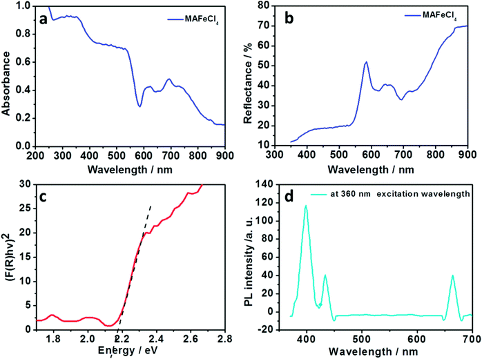
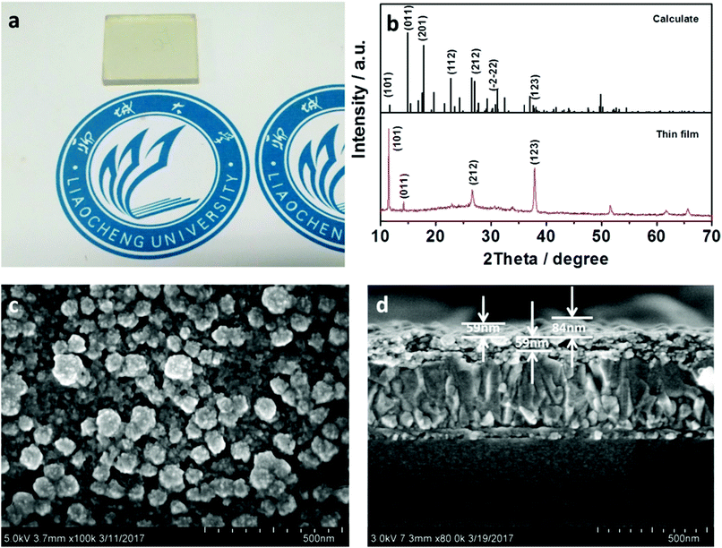
In order to characterize the absorbance properties of MAFeCl4, UV-Vis absorption spectra were recorded. The UV-Vis absorption spectrum of MAFeCl4 is shown in Fig. 2a. Strong absorption from 300 nm to 568 nm is observed. The absorbance of MAFeCl4 declined steeply from 539 nm to 582 nm, indicating the presence of the band gap. In order to characterize the reflection property of MAFeCl4, diffuse reflection spectroscopy was performed. The diffuse reflection spectrum of MAFeCl4 is shown in Fig. 2b. The reflectivity of MAFeCl4 decreases from 351 nm to 530 nm. The above results are consistent with the characteristics of the UV-visible absorption of MAFeCl4. In order to acquire the band gap of MAFeCl4, the diffuse reflectance spectrum was converted into the Kubelka–Munk spectrum (Fig. 2c). According to the Kubelka–Munk formula, F(R) = (1 − R)2/2R, where R represents the percentage of reflection, the relationship of the incident photon energy (hv) and Eg can be expressed as the transformed Kubelka–Munk relation, [F(R)hv]p = A(hv − Eg), where Eg is the band gap energy, A is the absorption constant, h is the Planck ’s constant, ν is the frequency of the light (s−1) and P is the power index that is related to the optical absorption process. Theoretically, P is equal to 1/2 or 2 for an indirect or a direct allowed transition, respectively. The Eg of MAFeCl4 was determined to be approximately 2.15 eV from the intercept of the linear plot on the X axis if MAFeCl4 is regarded as a directly allowed transition. After UV-Vis absorption spectroscopy and diffuse reflection spectroscopy for MAFeCl4 were performed, the photoluminescence (PL) spectroscopy of MAFeCl4 was also carried out. The PL spectrum of MAFeCl4 is shown in Fig. 2d. The emission peaks at 398, 432 and 664 nm are observed at 360 nm excitation wavelength. Thus, the PL characteristic of MAFeCl4 is attributed to these three emission peaks. MAFeCl4 thin films (Fig. 3a) were prepared by spin-coating a mixture of equimolar MACl and FeCl3 in DMF solution.
 | ||
| Fig. 2 (a–c) UV-Vis absorption spectrum, diffuse reflection spectrum and Kubelka–Munk spectrum of MAFeCl4, respectively; (d) photoluminescence spectrum of MAFeCl4 at 360 nm excitation wavelength. | ||
In order to determine the structure of the film, we recorded the XRD profiles of the MAFeCl4 thin film. The diffraction XRD results of the MAFeCl4 thin film on TiO2 are shown in Fig. 3b. The diffraction peaks of MAFeCl4 films on TiO2 were basically consistent with the diffraction peaks calculated from the MAFeCl4 single crystal. The corresponding crystal faces of each diffraction peak are shown in Fig. 3b. Strong peaks at 11.48°, 14.18°, 26.62°, and 37.91° are assigned to the (101), (011), (212), and (123) planes, respectively. In terms of the intensity of the peaks, the intensity of (101) peak was clearly stronger than that of the other peaks. These results suggest that the surface of the TiO2 electron collecting layer induces the growth of MAFeCl4 along the (101) plane. In order to study the morphology of the MAFeCl4 thin film, we carried out surface SEM analysis. The SEM test result is shown in Fig. 3c. It can be clearly seen that non-uniform-size nanoparticles were formed on the surface of the TiO2 layer. The sizes of the nanoparticles are about 50 to 90 nm. In order to test the uniformity and thickness of the FTO/TiO2/MAFeCl4 device, we tested the cross-sectional SEM image. The result is shown in Fig. 3d. The MAFeCl4 thin film is uniformly covered on the TiO2 film. The thickness of the MAFeCl4 film ranges from 59 nm to 84 nm. In addition, the thickness of the electron collection layer (TiO2) is uniform (about 59 nm).
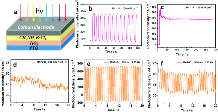
The photoresponse of MAFeCl4 has not been studied. Thus, photoresponsive devices based on MAFeCl4 were fabricated. We prepared a carbon electrode as the back electrode on the MAFeCl4 thin film by a doctor-blade, and evaluated the photoresponse by recording the photocurrent density–time characteristics. The ION/IOFF photocurrent density response of the MAFeCl4 device is clearly observed under ON/OFF illumination of AM 1.5 (100 mW cm−2) using a solar simulator (Fig. 4b). As time progressed, the photocurrent density increased. In order to determine the time required for the photocurrent density could attain stability, the photocurrent density–time characteristics of the FTO/TiO2/MAFeCl4/carbon electrode device were investigated under continuous illumination of AM 1.5 (100 mW cm−2) using a solar simulator (Fig. 4c). An evident photoresponse with maximum photocurrent density of 1352 nA cm−2 at 14.4 seconds was observed. The photocurrent density can stabilize after 54 seconds of illumination. In order to investigate the monochromatic photocurrent-response of the MAFeCl4 device, the monochromatic photocurrent response at different wavelengths with a flash frequency of 1.33 Hz was measured. The results are shown in Fig. 4. The ION/IOFF photocurrent density response of the MAFeCl4 device is not observed at 300 nm (Fig. 4d). At a wavelength of 330 nm, the ION/IOFF photocurrent density response is significantly enhanced (Fig. 4e). The ION/IOFF photocurrent response is also observed at a wavelength of 400 nm (Fig. 4f). At 410 nm, the ION/IOFF photocurrent response is significantly weaker, but still measurable (Fig. S1†). At 430 nm and 450 nm, the ION/IOFF photocurrent response was ineffective (Fig. S2 and S3†). The reason for this ineffective ION/IOFF photocurrent response from 400 to 558 nm might be due to the unreasonable device structure or the energy level mismatch. In the future, we will optimize the device structure and energy level of the HTM material to generate ION/IOFF photocurrent responses from 400 to 558 nm. The photoelectric conversion efficiency based on the FTO/TiO2/MAFeCl4/carbon electrode device reaches 0.054% (Voc = 319 mV, Jsc = 0.375 mA cm−2, and fill factor = 0.45) under AM1.5, 100 mW cm−2 simulated illumination (Fig. S4 and Table S3†).
The frequency of the writing-light is significant for the efficiency of an optical-logic device. The photoelectric responses of the MAFeCl4 device were investigated under 330 nm illumination with different chopping-frequencies (1.33 Hz, 40 Hz, 60 Hz, and 80 Hz). The results are shown in Fig. S5.† The best photoelectric response of the MAFeCl4 device is obtained at 1.33 Hz (Fig. S5a†). A stable photoelectric response is also observed at 40 Hz and 60 Hz (Fig. S5b and S5c†), which becomes weaker at 80 Hz (Fig. S5d†). Thus, the photocurrent–density response device is ineffective at 80 Hz. The effective photocurrent-response of the MAFeCl4 device at high frequencies was probed to enhance the efficiency of the MAFeCl4 optical-logic device. Our findings will be of interest in the magnetic, piezoelectric and photoelectronic research fields.
Conclusions
We prepared earth-abundant and environmentally friendly organic–inorganic CH3NH3FeCl4 (MAFeCl4) and studied its crystal structure, luminescence, band gap, adsorption properties and photoelectric behavior. The band gap of the orthorhombic MAFeCl4 was determined to be approximately 2.15 eV. A low cost photodetector based on the MAFeCl4 thin film is efficient under different monochromatic light ranging from 330 nm to 410 nm with different chopping frequencies (1.33 Hz to 40 Hz). Although the photoelectric conversion efficiency (0.054%) based on the FTO/TiO2/MAFeCl4/carbon electrode device is low, there will be significant room for improvement.Conflicts of interest
There are no conflicts to declare.Acknowledgements
This study was financially supported by the Shandong Province Natural Science Foundation (Grant No. ZR2016BQ20; BS2015NJ013; ZR2014BQ010; ZR2016BQ21), the Colleges and Universities in Shandong Province science and technology projects (Grant No. J16LC05), the Science and Technology Innovation Foundation for the University or College Students (Grant No. 26312160502), the National Science and Technology Innovation Foundation for the University or College Students (Grant No. 201510447021), the Research Fund for the Doctoral Program of Liaocheng University (Grant No. 31805), the National Natural Science Foundation of China (Grant No. 21503104; 21601078, 21401095) and the National Basic Research Program of China (Grant No. 2011CBA00701).Notes and references
- H.-S. Kim, C.-R. Lee, J.-H. Im, K.-B. Lee, T. Moehl, A. Marchioro, S.-J. Moon, R. Humphry-Baker, J.-H. Yum, J. E. Moser, M. Graetzel and N.-G. Park, Lead Iodide Perovskite Sensitized All-Solid-State Submicron Thin Film Mesoscopic Solar Cell with Efficiency Exceeding 9%, Sci. Rep., 2012, 2, 591 CrossRef PubMed.
- H. Zhu, Y. Fu, F. Meng, X. Wu, Z. Gong, Q. Ding, M. V. Gustafsson, M. T. Trinh, S. Jin and X. Y. Zhu, Lead halide perovskite nanowire lasers with low lasing thresholds and high quality factors, Nat. Mater., 2015, 14(6), 636–U115 CrossRef PubMed.
- L. Dou, Y. Yang, J. You, Z. Hong, W.-H. Chang and G. Li, Solution-processed hybrid perovskite photodetectors with high detectivity, Nat. Commun., 2014, 5, 5404 CrossRef PubMed.
- W. S. Yang, B. W. Park, E. H. Jung, N. J. Jeon, Y. C. Kim, D. U. Lee, S. S. Shin, J. Seo, E. K. Kim, J. H. Noh and S. I. Seok, Iodide management in formamidinium-lead-halide-based perovskite layers for efficient solar cells, Science, 2017, 356(6345), 1376–1379 CrossRef PubMed.
- B. Brun and P. Pouillart, Chemotherapy of metastatic breast cancer, Bull. Cancer, 2000, 87(9), 643–653 Search PubMed.
- T. C. Jellicoe, J. M. Richter, H. F. J. Glass, M. Tabachnyk, R. Brady, S. E. Dutton, A. Rao, R. H. Friend, D. Credgington, N. C. Greenham and M. L. Boehm, Synthesis and Optical Properties of Lead-Free Cesium Tin Halide Perovskite Nanocrystals, J. Am. Chem. Soc., 2016, 138(9), 2941–2944 CrossRef PubMed.
- C. C. Stoumpos, L. Frazer, D. J. Clark, Y. S. Kim, S. H. Rhim, A. J. Freeman, J. B. Ketterson, J. I. Jang and M. G. Kanatzidis, Hybrid Germanium Iodide Perovskite Semiconductors: Active Lone Pairs, Structural Distortions, Direct and Indirect Energy Gaps, and Strong Nonlinear Optical Properties, J. Am. Chem. Soc., 2015, 137(21), 6804–6819 CrossRef PubMed.
- A. H. Slavney, T. Hu, A. M. Lindenberg and H. I. Karunadasa, A Bismuth-Halide Double Perovskite with Long Carrier Recombination Lifetime for Photovoltaic Applications, J. Am. Chem. Soc., 2016, 138(7), 2138–2141 CrossRef PubMed.
- Z. H. Nie, J. Yin, H. W. Zhou, N. Chai, B. L. Chen, Y. T. Zhang, K. G. Qu, G. D. Shen, H. Y. Ma, Y. C. Li, J. S. Zhao and X. X. Zhang, Layered and Pb-Free Organic-Inorganic Perovskite Materials for Ultraviolet Photoresponse: (010)-Oriented (CH3NH3)(2)MnCl4 Thin Film, ACS Appl. Mater. Interfaces, 2016, 8(41), 28187–28193 Search PubMed.
- X. Zhang, J. Yin, Z. Nie, Q. Zhang, N. Sui, B. Chen, Y. Zhang, K. Qu, J. Zhao and H. Zhou, Lead-free and amorphous organic–inorganic hybrid materials for photovoltaic applications: mesoscopic CH3NH3MnI3/TiO2 heterojunction, RSC Adv., 2017, 7(59), 37419–37425 RSC.
- X. Li, X. Zhong, Y. Hu, B. Li, Y. Sheng, Y. Zhang, C. Weng, M. Feng, H. Han and J. Wang, Organic–Inorganic Copper(II)-Based Material: A Low-Toxic, Highly Stable Light Absorber for Photovoltaic Application, J. Phys. Chem. Lett., 2017, 8(8), 1804–1809 CrossRef PubMed.
Footnote |
| † Electronic supplementary information (ESI) available. CCDC 1585495. For ESI and crystallographic data in CIF or other electronic format see DOI: 10.1039/c8ra03498b |
| This journal is © The Royal Society of Chemistry 2018 |


