
 Open Access Article
 This Open Access Article is licensed under a Creative Commons Attribution-Non Commercial 3.0 Unported Licence
MoS2 formation induced by amorphous MoS3 species under lubricated friction
C. Oumahi *a,
M. I. De Barros-Bouchetb,
T. Le Mogneb,
C. Charrinc,
S. Loridanta,
C. Geanteta,
P. Afanasiev*a and
B. Thiebautc
*a,
M. I. De Barros-Bouchetb,
T. Le Mogneb,
C. Charrinc,
S. Loridanta,
C. Geanteta,
P. Afanasiev*a and
B. Thiebautc
aUniversité LYON I, Institut de Recherches sur la Catalyse et l’Environnement de Lyon (IRCELYON), CNRS UMR5256, Villeurbanne, France. E-mail: camella.oumahi@gmail.com; pavel.afanasiev@ircelyon.univ-lyon1.fr
bUniversité de Lyon I, Laboratoire de Tribologie et Dynamique des Systèmes, CNRS UMR5513, 69134 Ecully, France
cTOTAL, Solaize Research Center, BP22-69360 Cedex, France
First published on 19th July 2018
Abstract
Amide molybdate has been recently introduced as a friction modifier for tribological applications. Combined with zinc dithiophosphate (ZDDP) and fatty amines, it provides an ultralow friction coefficient. The ultimate product of Mo compound transformations in tribological contact, due to frictional heating and shearing, as well as chemical interactions with oil additives, is molybdenum sulfide (MoS2). Understanding the decomposition of amide molybdate leading to MoS2 is of primary importance to the optimization of the design of lubricant formulations. This study focuses on the investigation by Raman spectroscopy of amide molybdate decomposition intermediates. Raman spectra of tribofilms, obtained after friction tests under different temperatures and pressures, revealed the formation of an amorphous MoS3 intermediate coexisting with MoS2. However, under severe conditions, the tribofilms are mostly composed of MoS2.
1. Introduction
Molybdenum disulfide (MoS2) is a material extensively used in hydrotreating catalysts,1,2 photocatalysts,3 electrodes in Li-ion batteries,4 or lubricants.5 In tribology, MoS2 is known for its low shearing at sliding interfaces. For example, Martin et al.6 reported an ultralow friction coefficient in the range of 10−3 in an ultrahigh vacuum. Such an ultralow friction coefficient is characterized by a friction-induced orientation of the planes parallel to the sliding direction of the MoS2 nanoparticles.6,7 Among molybdenum-based friction modifiers that have been proposed up until now,8,9 oil-soluble molybdenum dithiocarbamate (MoDTC) is widely used as a MoS2 source since it permits the reach of an ultralow friction coefficient in the range 0.05–0.08.10–13 Unfortunately, MoDTC friction modifiers suffer from low stability against oxidation, which leads to a loss of efficiency under friction.11,14,15 The main additive degradation mechanism is due to a sulfur–oxygen atom substitution, which leads to oxidation and finally to the loss of the efficient MoDTC molecule.19 An alternative option to limit the oxidation instability involves the use of a sulfur-free organic molybdenum molecule, combined with a molecule acting as a sulfur source. Amide molybdate, where molybdenum is present in the form of an oxygenated Mo(VI) species, is such a candidate.16–21 De Barros Bouchet et al.22 have recently shown that, once combined with the antiwear zinc dialkyl dithiophosphate ZDDP (which also brings S into the mixture) and a fatty amine, amide molybdate shows a beneficial effect toward lubrication. In addition to an ultralow friction coefficient of 0.02 under boundary lubrication conditions, this mixture is stable over time. A chemical pathway was proposed to explain MoS2 formation from amide molybdate. After reacting with the fatty amine, amide molybdate is sulfided into MoS3 in the presence of ZDDP. Then, under shear, MoS3 forms MoS2.In the case of MoDTC, many attempts have been made to explain the reaction mechanism of MoS2 formation from MoDTC decomposition upon friction contact. Sakurai et al.23 suggested homolytic fission of the Mo–S bonds between the [MoO2S2]2− core and dithiocarbamate ligands. This mechanism was supported by Grossiord et al. using XPS spectroscopy.24 Another route for MoDTC decomposition through C–S bond cleavage was also suggested by Coffey et al.25 However, few studies have been performed on amide molybdate.16–21
This work focuses on the combination of amide molybdate, ZDDP, and fatty triamine. Our aim is to understand the intermediates involved in MoS2 formation under friction of this ternary mixture of components. For this purpose, friction tests of the ternary mixtures were conducted at different pressures and temperatures. Then, the tribofilms were spatially characterized by micro-Raman mapping.
2. Experimental
2.1. Lubricant mixtures and solid reference preparation
The lubricants were composed of an amide molybdate friction modifier (Fig. 1), antiwear zinc dialkyldithiophosphate (ZDDP) synthesized from a secondary alcohol (Fig. 1), and a fatty triamine (Fig. 1). They were respectively purchased from Vanderbilt, Lubrizol, and AkzoNobel.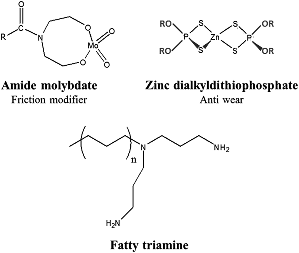 | ||
| Fig. 1 Lubricant additives: amide molybdate, zinc dialkyldithiophosphate (ZDDP), and fatty triamine. | ||
To prepare the lubricant compositions, 400 ppm of Mo amide molybdate, 1% wt of ZDDP, and 0.5% wt of fatty triamine were added to a base oil (PAO4) in a glass vessel and mixed by stirring.
2.2. Reference preparation
The bulk MoS2 and amorphous MoS3 references were prepared by thermal decomposition of ammonium tetrathiomolybdate (NH4)2MoS4, at 500 °C under hydrogen and at 200 °C under nitrogen, respectively.2.3. Tribological experiments
A linear reciprocating friction tribometer with a ball-on-flat configuration was used to generate tribofilms under severe tribological conditions. The selected contact configuration was composed of an AISI 52100 steel ball (6.7 mm radius)/AISI 52100 steel flat. This alloy is a high carbon and chromium-containing bearing steel (0.95–1.10 % C, 0.35 max % Si, 0.20–0.50 % Mn, 0.025 max % P, 0.025 max % S, and 1.30–1.60 % Cr) with a high hardness of about 9 GPa and excellent strength and fatigue properties. The friction experiments were performed at different temperatures and maximum initial contact pressures (the conditions are summarized in Table 1), and with a maximum sliding speed of about 0.1 m s−1 (center of the track) for a one-hour duration. No run-in period prior to the sliding experiment was performed. Prior to the experiment, both the ball and flat specimens were ultrasonically cleaned in a heptane bath for 30 min in order to remove surface contaminants. The composite roughness of the two surfaces was about 25 nm. An average friction coefficient for each sliding cycle was calculated from one thousand measurements of instantaneous friction coefficients recorded during the cycle.| Conditions | Normal force (N) | Maximal contact pressure (MPa) | Temperature (°C) | Mean friction coefficient (μ) |
|---|---|---|---|---|
| 1 | 3 | 400 | 80 | 0.069 |
| 2 | 7 | 540 | 60 | 0.108 |
| 3 | 7 | 540 | 70 | 0.078 |
| 4 | 7 | 540 | 80 | 0.034 |
| 5 | 7 | 540 | 90 | 0.036 |
| 6 | 7 | 540 | 100 | 0.034 |
| 7 | 7 | 540 | 110 | 0.035 |
| 8 | 15 | 700 | 80 | 0.036 |
2.4. Characterization
Confocal Raman spectra were recorded with a LabRam HR Raman spectrometer (Horiba-Jobin Yvon). The exciting laser at 514.5 nm (Ar laser) was focused using a ×50 long working distance objective, leading to spatial resolution of ca. 4 μm. Laser power of 1 mW was used after checking for the absence of laser heating effects. The spectral resolution was lower than 4 cm−1. After the friction tests, the samples were washed for 30 min in a heptane bath under sonication. The Raman mapping analyses were performed on the center of the tribofilms, on a section measuring 50 per 100 μm, with a step of 8 μm, and an autofocus was automatically performed before each analysis. The spectra were first recorded horizontally along a line, before recording vertically to the bottom line (Fig. 2). Each tribofilm was characterized by a mapping sequence containing 117 raw spectra (9 × 13). Analyses were done under the same conditions of laser power and acquisition time.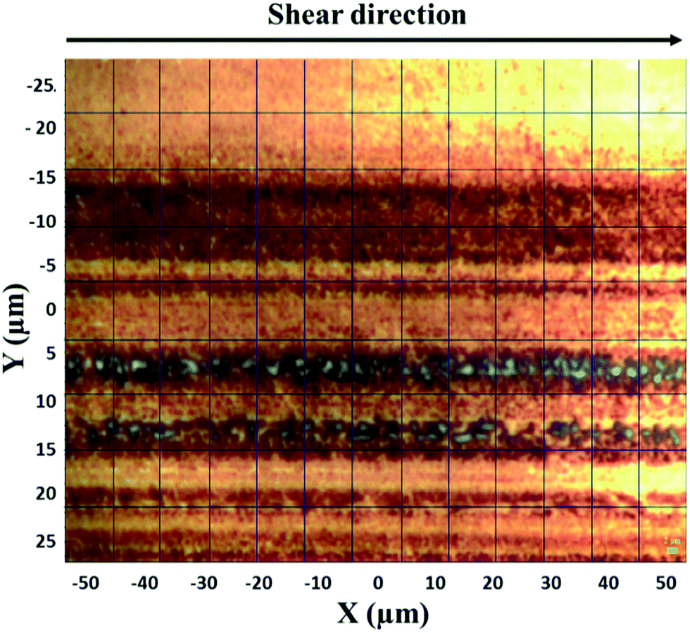 | ||
| Fig. 2 Example of an optical microscopy picture of an analyzed section (50 per 100 μm). During the mapping, each square of the image was analyzed. | ||
Elemental analysis of the reference solids was carried out using atomic emission spectroscopy. The mixtures were mineralized at 350/400 °C with a solution made of H2SO4 and HNO3. The amounts of Mo and S were measured by Inductively Coupled Plasma Optical Emission Spectroscopy (ICP-OES) using an ACTIVA Horiba Jobin Yvon spectrometer.
3. Results and discussion
3.1. Friction tests
The friction coefficient (FCo) data and FCo time evolution curves during the friction tests are respectively shown in Table 1 and Fig. 3. At a constant contact pressure of 7 N (corresponding to a maximal contact pressure of 540 MPa), the FCo is highly dependent on the temperature. At 60 °C, the FCo is 0.108, and it decreases between 60 and 110 °C until it reaches a plateau around 0.035. Then, the temperature was fixed at 80 °C and we varied the contact pressure. At 3 N (corresponding to a maximal contact pressure of 400 MPa), the FCo is 0.069, but it decreases to 0.035 at 7 and 15 N. This decrease in friction under severe conditions has already been observed in the literature.10,26,27 The contribution of thermal and mechanical energies is essential to ensure the molecule decomposition and the tribofilm formation. The tribofilms formed during the tests conducted at different temperatures and pressures were then analyzed by Raman spectroscopy.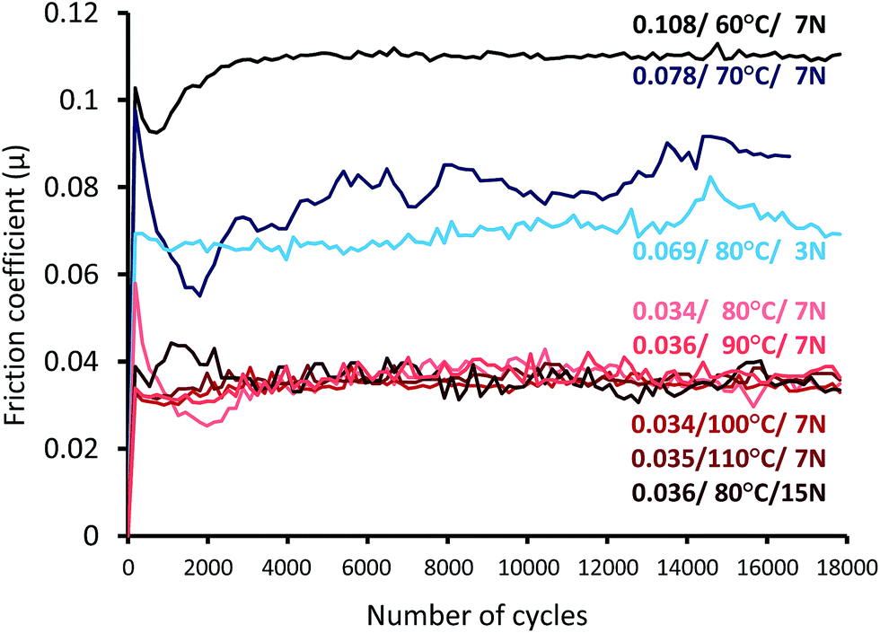 | ||
| Fig. 3 Evolution of the friction coefficient as a function of the cycle number under different conditions, as indicated in Table 1. | ||
3.2. Characterization by Raman spectroscopy
Confocal Raman spectroscopy mapping is particularly convenient when using flat steel samples and it allows for the spatially resolved characterization of the tribofilms, as well as the identification of the reaction intermediates.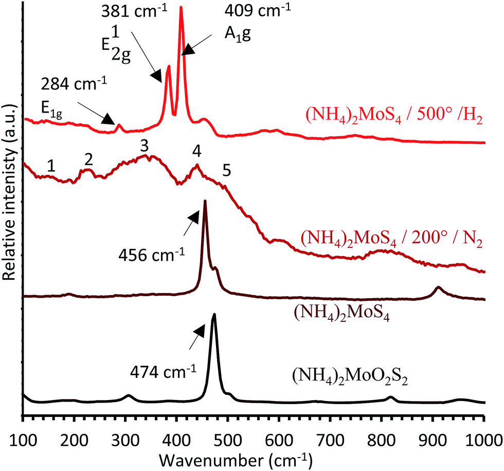 | ||
| Fig. 4 Reference spectra of (NH4)2MoO2S2, (NH4)2MoS4, (NH4)2MoS4 decomposed at 200 °C under N2, and (NH4)2MoS4 decomposed at 500 °C under H2. | ||
The Raman spectra of the MoS3 and MoS2 references prepared via the thermal decomposition of (NH4)2MoS4 at 200 °C under nitrogen and 500 °C under H2, respectively, are presented in Fig. 4.
Crystalline MoS2, obtained from the decomposition of (NH4)2MoS4 at 500 °C under H2, has three active Raman bands, E1g, E12g, and A1g, respectively located at 284, 381, and 409 cm−1 (Fig. 4), in agreement with the literature.31 The amorphous species, prepared by the decomposition of (NH4)2MoS4 at 200 °C under N2, shows several broad bands (Fig. 4). These bands, numbered from 1 to 5 in Fig. 4, are closely located to the ones reported in literature for MoS3.32 MoS3 is characterized by five bands in the ranges 150–160 cm−1, 210–220 cm−1 (both corresponding to the δ(Mo–S) angular mode), 300–360 cm−1, 425–450 cm−1 (both corresponding to the ν(Mo–S) stretching modes), and 520–550 cm−1 (corresponding to the ν(S–S) stretching modes).31,33–35
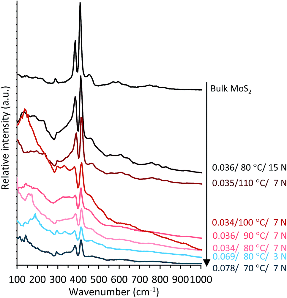 | ||
| Fig. 5 Raman mean spectra of the tribofilms obtained under different temperature and pressure conditions. The tribofilm spectra are compared to those of the bulk MoS2 reference. | ||
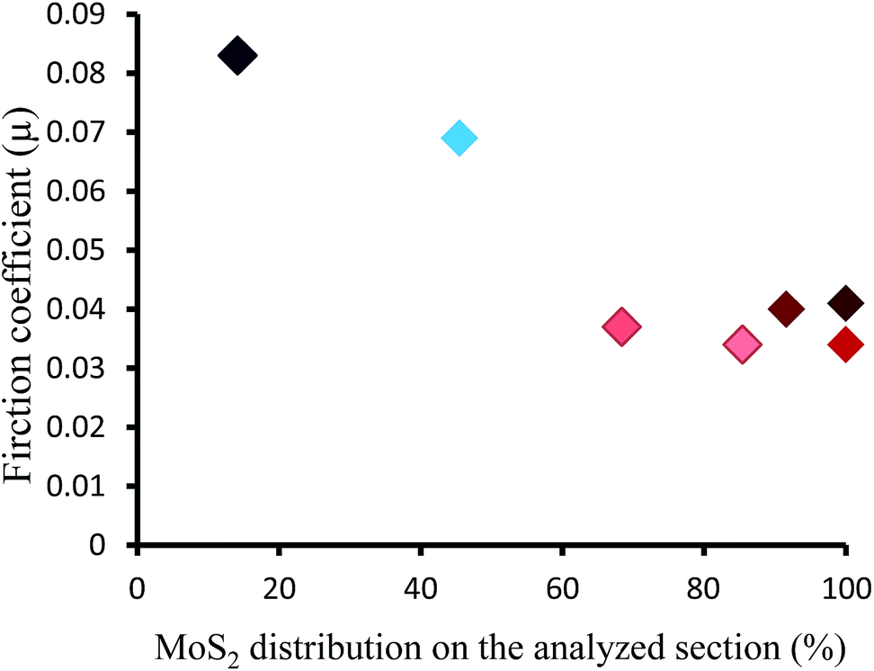
There are neither (NH4)2MoS4 nor (NH4)2MoO2S2 signatures in the Raman spectra. The absence of any significant features both above 600 cm−1 and between 800 and 1000 cm−1 attests to the fact that no oxide forms of molybdenum (molybdate, MoO3, etc.) are present in the tribofilms. However, we observe intense A1g and E12g bands of MoS2, evidencing its expected formation in the tribofilms. Moreover, as seen in Fig. 6, the decrease in FCo is accompanied by an increase in the MoS2 distribution in the tribofilms. In contrast to bulk MoS2, which exhibits narrow bands, the tribofilm spectra exhibit broad bands between 280–400 and 400–550 cm−1 (Fig. 5). This suggests that MoS2 is formed together with an amorphous species. Moreover, the band intensity and narrowness increase with temperature (from 70 to 110 °C) and pressure (from 3 N to 15 N). Therefore, the crystallinity of MoS2 increases under more severe conditions. The broad peak in the 100–250 cm−1 region is attributed to stress-induced disorder in the MoS2 crystal structure (Fig. 5).36,37
 | ||
| Fig. 6 Evolution of the friction coefficient vs. the proportion of spectra containing MoS2 in the tribofilms. For this measurement, every spectrum containing MoS2 was counted, independent of the presence of amorphous species. We fixed a threshold value of 1.1, corresponding to the intensity ratio of the MoS2 A1g band with respect to the amorphous species band located at 400–550 cm−1, in order to consider the presence of MoS2. | ||
In order to distinguish the different species present in the tribofilms, we focused our study on mapping the test conducted at 90 °C and 7 N (Fig. 5). As seen in Fig. 7, the intensity of the A1g band is relatively homogeneous across the tribofilm, except for line 6, where the intensity of the A1g band of MoS2 is the lowest. By analyzing the mean spectrum per line (Fig. 8a), as we move across the map from line 0 to 8, i.e. from the center of tribofilm to the periphery, it can be seen that the intensity of the A1g and E12g bands decreases, with the amorphous band hiding the E12g band. This amorphous contribution is the most pronounced for line 6. It is even clearer once all the individual spectra of line 6 are compared (Fig. 8b). The A1g band of MoS2 at 410 cm−1 is only seen in the last columns of the raw spectra. Then, we compared these broad bands to the Raman spectrum of the MoS3 reference (Fig. 9), and they appear rather similar. The blue spectrum of line 6 has broad bands similar to that of the MoS3 reference (in the ranges 260–400 and 410–580 cm−1). Therefore, the amorphous species formed in competition (or as an intermediate) with MoS2 are of MoS3 type.
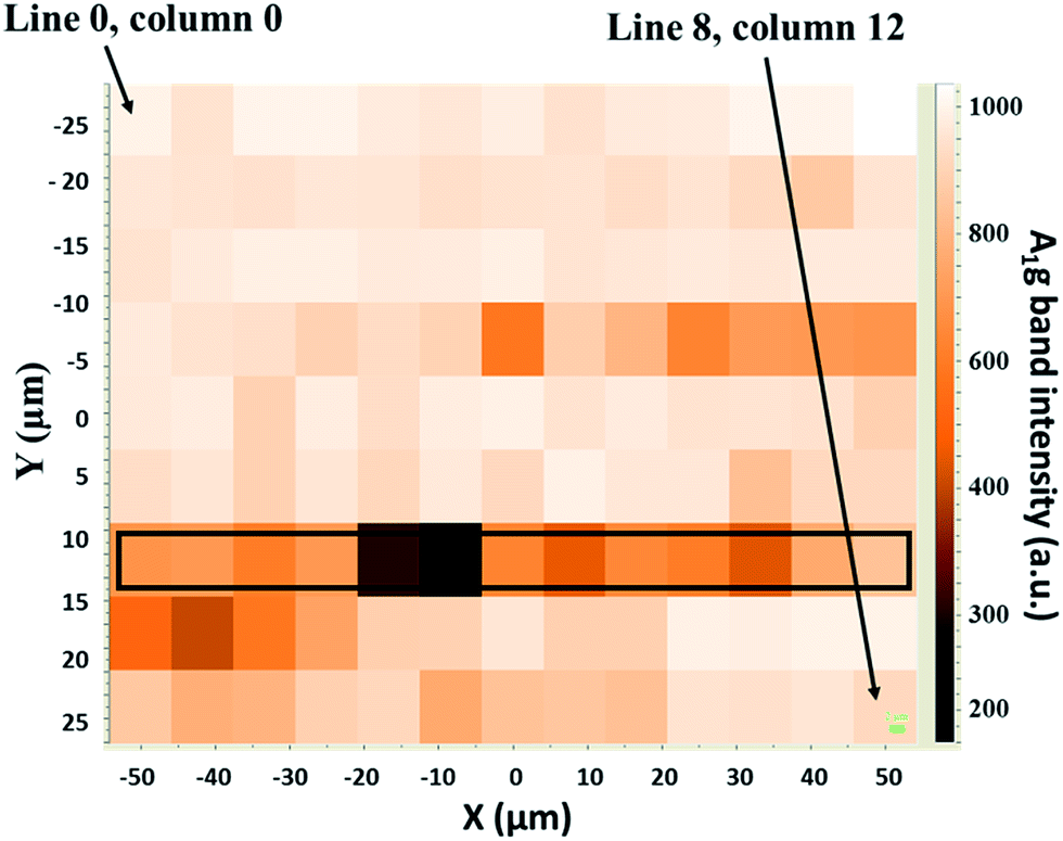 | ||
| Fig. 7 Intensity of the A1g band according to the location on the tribofilm obtained from the mixture of amide-Mo, ZnDTP, and triamine at 90 °C. The intensity increases from dark (no MoS2) to bright areas (more MoS2). | ||
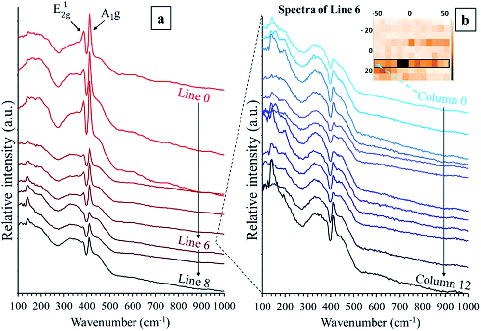 | ||
| Fig. 8 Raman spectra of the tribofilm from the mixture of amide-Mo, ZnDTP, and triamine at 90 °C: (a) mean spectrum for each line (from 0 to 8), and (b) individual spectra of line 6. | ||
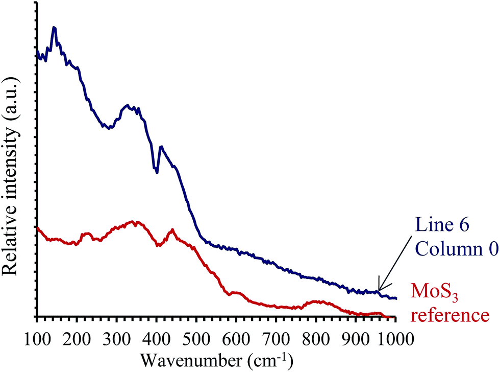 | ||
| Fig. 9 Raman spectrum of the amorphous species from line 6, in comparison with that of the MoS3 amorphous species made via the decomposition of (NH4)2MoS4 at 200 °C. | ||
The sulfur–rich sulfide, MoS3, known for its catalytic38 and electrochemical properties,34,39,40 can only be prepared as an amorphous substance. MoS3 can be prepared by acidic precipitation of (NH4)2MoS4,41 by reacting molybdenum halides with hexamethyldisilathiane,34 or as in the present work, by gentle thermal decomposition of (NH4)2MoS4. Its structure is not exactly clear and different models have been proposed, including chain-like and trimeric structures,42–45 which cannot mutually be excluded because the chemical connectivity in an amorphous solid might strongly depend on the preparation technique used to obtain it. This type of species has already been observed in materials derived from tribological experiments. Khaemba et al.,13,46,47 reported its formation as a sulfur-rich MoSx species, an intermediate in the decomposition of MoDTC to MoS2 under soft friction conditions. Moreover, whereas no more species other than MoS3 and MoS2 were observed in that study, the authors reported the simultaneous formation of MoSx (x ∼ 3), MoS2, and FeMoO4 species.46
For molybdenum-containing lubricants, it is widely accepted that friction reduction is achieved due to the formation of MoS2 single sheets in the contact zone.24,48,49 The widely used MoDTC molecule already contains three sulfur atoms per molybdenum atom, sufficient to stoichiometrically form MoS3 and then MoS2, due to an intramolecular decomposition process induced by applied stress and temperature. As amide molybdate is an oxidic precursor, molybdenum sulfide species are formed in a complex process involving interaction with the sulfur-containing ZDDP molecule. Therefore, pathways involving different possible intermediates may occur. Herein, we clearly demonstrate that the only intermediate present in the tribofilms, in a tangible amount, is an amorphous MoS3-like sulfide. Remarkably, no oxygenated Mo species are detected in the tribofilm.
Raman mapping strongly suggests that MoS3 is an intermediate and not an extraneous compound formed alongside MoS2. Indeed, as the mapping point moves from the center of the zone towards the periphery, the relative amount of MoS3 increases and that of MoS2 decreases. This evolution obviously occurs in relation to the local temperature and pressure created in the contact zone by the ball friction. Indeed, according to TGA measurements under nitrogen, the [MoS4]2− species first decomposes to MoS3 between 120 to 260 °C and then MoS3 decomposes to MoS2 above 300 °C, i.e. at higher temperatures than the ones used during the tribotest.50
4. Conclusions
This work focused on the decomposition mechanism of amide molybdate as a friction modifier additive. Combined with ZDDP and fatty amine, it provides an ultralow friction coefficient under severe lubricating conditions. In order to investigate the decomposition mechanism of amide molybdate, two series of experimental friction tests were performed, varying the temperature and pressure. The results show that the friction decreases as the severity of the conditions increases. The tribofilm compositions were analyzed using confocal Raman spectroscopy. Under softer conditions, amorphous species are mainly formed, coexisting with MoS2. However, under severe conditions, MoS2 is mostly formed. The amorphous species are attributed to a MoS3-type compound, which is an intermediate during the formation of MoS2. However, if ultralow friction is not achieved, MoS3 is found in the final tribofilm, coexisting with MoS2. It is possible to modulate the test conditions in order to ensure MoS2 formation and to limit MoS3 formation. However, given the fact that engine conditions differ from one part to another, it would be interesting to design another Mo-containing friction modifier that could produce MoS2 across a larger range of friction conditions.Conflicts of interest
There are no conflicts to declare.References
- H. Topsøe, Appl. Catal., A, 2007, 322, 3–8 CrossRef
.
- L. Van Haandel, G. M. Bremmer, E. J. M. Hensen and T. Weber, J. Catal., 2017, 351, 95–106 CrossRef
- Z. Lei, W. You, M. Liu, G. Zhou, T. Takata and M. Hara, Chem. Commun., 2003, 2142–2143 RSC
- L. Ye, C. Wu, W. Guo and Y. Xie, Chem. Commun., 2006, 2, 4738 RSC
- M. Chhowala and G. A. J. Amaratunga, Nature, 2000, 407, 164–167 CrossRef PubMed
- J. M. Martin, C. Donnet, T. Le Mogne and T. Epicier, Phys. Rev. B: Condens. Matter Mater. Phys., 1993, 48, 10583–10586 CrossRef
- J. M. Martin, H. Pascal, C. Donnet, T. Le Mogne, J. L. Loubet and T. Epicier, Surf. Coat. Technol., 1994, 69, 427–432 CrossRef
- P. C. H. Mitchell, Wear, 1984, 100, 281–300 CrossRef
- H. Spikes, Tribol. Lett., 2015, 60, 1–26 CrossRef
- J. Graham and S. Korcek, Tribol. Trans., 2001, 44, 626–636 CrossRef
- M. De Feo, C. Minfray, M. I. De Barros-Bouchet, B. Thiebaut, T. Le Mogne, B. Vacher and J. M. Martin, Tribol. Int., 2015, 92, 126–135 CrossRef
- A. Morina, A. Neville, J. H. Green and M. Priest, in Tribology and Interface Engineering Series, ed. D. Dowson, M. Priest, G. Dalmaz and A. A. Lubrecht, Elsevier Masson SAS, 2005, vol. 48, pp. 757–767 Search PubMed
- D. N. Khaemba, F. Jarnias, B. Thiebaut, A. Neville and M. J. Ardian, J. Phys. D: Appl. Phys., 2017, 50, 085302–085310 CrossRef
- M. De Feo, C. Minfray, M. I. De Barros-Bouchet, B. Thiebaut and J. M. Martin, RSC Adv., 2015, 5, 93786–93796 RSC
- M. De Feo, M. I. De Barros-Bouchet, C. Minfray, T. Le Mogne, F. Meunier, L. Yang, B. Thiebaut and J. M. Martin, Wear, 2016, 348, 116–125 CrossRef
- O. Gorbatchev, M. I. De Barros Bouchet, J. M. Martin, D. Léonard, T. Le-Mogne, R. Iovine, B. Thiebaut and C. Héau, Tribol. Int., 2016, 99, 278–288 CrossRef
- M. Debord, C. Charrin and J. Guerin, Composition lubrifiante à fuel éco longue durée, FR3039165A1, 2015
- Y. F. Suen and J. H. McLain, Multifunctional molybdenum containing compounds, method of making and using, and lubricating oil compositions containing same, US20160369199A1, 2016
- K. Fletcher, W. Y. Lam, K. Yang and J. Styer, Lubricating with molybdenum and their use for improving low speed pre-ignition, US20170015929A1, 2017
- M. K. Patel and V. J. Gatto, Additive for lubricant compositions comprising a sulfur-free organomolybdenum compound, and triazole or a derivated triazole, US20170044456A1, 2017
- R. Iovine and C. Charrin, Lubricant composition based on neutralized amines and molybdenum, WO2017149119A1, 2017
- M. I. De Barros Bouchet, J. M. Martin, C. Oumahi, O. Gorbatchev, P. Afanasiev, C. Geantet, R. Iovine, B. Thiebaut and C. Heau, Tribol. Int., 2018, 119, 600–607 CrossRef
- T. Sakurai, H. Okabe and H. Isoyama, Bull. Jpn. Pet. Inst., 1971, 13, 243–249 CrossRef
- C. Grossiord, K. Varlot, J. M. Martin, T. Le Mogne, C. Esnouf and K. Inoue, Tribol. Int., 1998, 31, 737–743 CrossRef
- A. Coffey, G. D. Forster and G. J. Hogarth, J. Chem. Soc., Dalton Trans., 1996, 2, 183–193 RSC
- J. Graham, H. Spikes and R. Jensen, Tribol. Trans., 2001, 4, 37–41 Search PubMed
- Y. Tamai, T. Inazumi and K.-I. J. Manabe, J. Mater. Process. Technol., 2016, 227, 161–168 CrossRef
- T. Decamp, Etude de l’évolution des propriétés adsorbantes et catalytiques des sulfures de métaux de transition en fonction du rapport soufre sur métal, Thèse de doctorat en Sciences, Catalyse, Lyon 1, 1992
- J. W. McDonald, G. D. Friesen, L. D. Rosenhein and W. E. Newton, Inorg. Chim. Acta, 1983, 72, 205–210 CrossRef
- A. Muller, W. Jaegermann and W. J. Hellmann, J. Mol. Struct., 1983, 100, 559–570 CrossRef
- C. H. Chang and S. S. Chan, J. Catal., 1981, 72, 139–148 CrossRef
- M. Olga Guerrero-Perez, E. Rojas, A. Gutierez-Alejandre, J. Ramıez, F. Sachez-Minero, C. Fernadez-Vargas and M. A. Banãres, Phys. Chem. Chem. Phys., 2011, 13, 9260–9267 RSC
- R. N. Bhattacharya, C. Y. Lee and F. H. J. Pollak, J. Non-Cryst. Solids, 1987, 91, 235–242 CrossRef
- C. Sourisseau, O. Gorochov and D. M. Schleich, J. Mater. Sci. Eng. B, 1989, 3, 113–117 CrossRef
- T. Weber, J. C. Muijsers and J. W. J. Niemantsverdriet, J. Phys. Chem., 1995, 99, 9194–9200 CrossRef
- N. T. McDevitt, J. S. Zabinski, M. S. Donley and J. E. Bultman, Appl. Spectrosc., 1994, 48, 733–736 CrossRef
- N. T. McDevitt, J. E. Bultman and J. S. Zabinski, Appl. Spectrosc., 1998, 52, 2–6 CrossRef
- B. Liu, Z. Jin, L. Bai, J. Liang, Q. Zhang, N. Wang, C. Liu, C. Wei, Y. Zhao and X. Zhang, J. Mater. Chem. A., 2016, 4, 14204–14212 RSC
- H. Shin, H. J. Doerr, C. Deshpandey, P. Fuqua, B. Dunn and R. F. Bunshah, Surf. Coat. Technol., 1988, 36, 859–865 CrossRef
- Y. Deng, L. R. L. Ting, P. H. L. Neo, Y. J. Zhang, A. A. Peterson and B. S. Yeo, ACS Catal., 2016, 6, 7790–7798 CrossRef
- J. C. Wildervanck and F. Jellinek, Z. Anorg. Allg. Chem., 1964, 328, 309–318 CrossRef
- S. J. Hibble, D. A. Rice, D. M. Pickup and M. P. Beer, Inorg. Chem., 1995, 34, 5109–5113 CrossRef
- S. J. Hibble, R. I. Walton, D. M. Pickup and A. C. J. Hannon, J. Non-Cryst. Solids, 1998, 232–234, 434–439 CrossRef
- K. S. Liang, J. P. DeNeufville, A. J. Jacobson and R. R. J. Chianelli, J. Non-Cryst. Solids, 1980, 36, 1249–1254 CrossRef
- F. Z. Chien, S. C. Moss, K. S. Liang and R. R. Chianelli, Phys. Rev.
B: Condens. Matter Mater. Phys., 1984, 29, 4606–4615 CrossRef
- D. N. Khaemba, A. Neville and A. Morina, RSC Adv., 2016, 6, 38637–38646 RSC
- D. N. Khaemba, A. Neville and A. Morina, Tribol. Lett. Lett., 2015, 59, 1–17 CrossRef
- J. M. Martin, C. Grossiord, T. Le Mogne and J. Igarashi, Wear, 2000, 245, 107–115 CrossRef
- M. I. De Barros Bouchet, J. M. Martin, T. Le Mogne, P. Bilas, B. Vacher and Y. Yamada, Wear, 2005, 258, 1643–1650 CrossRef
- J. L. Brito, M. Ilija and P. Hernández, Thermochim. Acta, 1995, 256, 325–338 CrossRef
| This journal is © The Royal Society of Chemistry 2018 |