 Open Access Article
A series of new polyoxometalate-based metal–organic complexes with different rigid pyridyl-bis(triazole) ligands: assembly, structures and electrochemical properties†
Xiuli Wang *,
Xue Bai,
Hongyan Lin,
Junjun Sun,
Xiang Wang and
Guocheng Liu
Department of Chemistry, Bohai University, Jinzhou, 121000, P. R. China. E-mail: wangxiuli@bhu.edu.cn; Fax: +86-416-3400158; Tel: +86-416-3400158
First published on 20th June 2018
Abstract
Five new polyoxometalate (POM)-based metal–organic complexes (MOCs) with different rigid pyridyl-bis(triazole) ligands, namely, H{Co2(Hpyttz-I)2(H2O)6[CrMo6(OH)6O18]}·8H2O (1), {Co2(H2pyttz-I)2(H2O)4[TeMo6O24]}[Co(H2O)6]·3H2O (2), {Co3(Hpyttz-II)2(H2O)6[γ-Mo8O26]}·10H2O (3), {Ni3(Hpyttz-II)2(H2O)6[γ-Mo8O26]}·10H2O (4), {Ni3(Hpyttz-III)2(H2O)8[γ-Mo8O26]}·10H2O (5) (H2pyttz-I = 3-(pyrid-2-yl)-5-(1H-1,2,4-triazol-3-yl)-1,2,4-triazolyl, H2pyttz-II = 3-(pyrid-3-yl)-5-(1H-1,2,4-triazol-3-yl)-1,2,4-triazolyl, H2pyttz -III = 3-(pyrid-4-yl)-5-(1H-1,2,4-triazol-3-yl)-1,2,4-triazolyl), were successfully synthesized and structurally characterized by single-crystal X-ray diffraction, IR spectra, powder X-ray diffraction (PXRD) and thermogravimetric analyses (TGA). Complex 1 is a two-dimensional (2D) supramolecular network based on the binuclear complex unit: [Co2(Hpyttz-I)2(H2O)6 [CrMo6(OH)6O18]]. Complex 2 is a 1D supramolecular chain derived from the binuclear cobalt complex: {Co2(H2pyttz-I)2(H2O)4[TeMo6O24]}2−, the discrete [Co(H2O)6]2+ units act as counter cations. Complexes 3 and 4 are isostructural with different center metals (M = Co or Ni), the adjacent γ-Mo8O264− anions are linked by the MII ions to form a 1D M-γ-Mo8O26 inorganic chain. Then 1D M-γ-Mo8O26 inorganic chains are linked together by the 1D metal–organic M-(Hpyttz-II) chains to form a 3D framework. In complex 5, γ-Mo8O264− anions are bridged by the NiII ions to give a 1D Ni-γ-Mo8O26 inorganic chain, the adjacent 1D Ni-γ-Mo8O26 chains are connected through [Ni(Hpyttz-III)2] units to form a 2D layer. The effect of POM type and coordination site of the ligands on the structures of the title complexes were discussed. The title complexes 1, 2 and 5 exhibit excellent bifunctional electrocatalytic activities toward the reduction of bromate/hydrogen peroxide and the oxidation of ascorbic acid. In addition, the redox potentials of complexes 1, 2 and 5 are highly sensitive to pH and may be used as a kind of potential pH sensor.
Introduction
Polyoxometalates (POMs) have been attracting extensive interest in the areas of chemistry and materials, owing to their physicochemical properties and important potential applications in medicine, catalysis, electrochemistry and materials science.1 Many POMs-based metal–organic complexes (MOCs) with different organic ligands have been reported, in which POMs were used as building subunits or templates.2 In recent years, considerable progress has been made on designing POM-based MOCs materials,3 due to their potential applications in the fields of biology, materials chemistry, catalysis, medicine, electronics, electrochemistry, and so on.4Electrocatalytic materials have received considerable attention owing to their potential applications in electrochemical sensors and the hydrogen evolution reaction (HER) or oxygen evolution reaction (OER).5 Recently, the introduction of POMs into electrocatalytic materials represents an exciting direction based on their ability to undergo reversible redox process, which is the most important properties of POM anions.6a For example, Das' group has shown that Keggin anion [CoW12O40]6− turned into an efficient and robust water oxidation electrocatalyst upon its confinement in the well-defined void space of a metal organic framework ZIF-8, ([H6CoW12O40]@ZIF-8).6b Wang's group obtained a new POM-based MOCs with polyrotaxane structure {Ag8O(Htrz)4(4,4′-bpy)2}{AgPMo12O40} (Htrz = 1,2,4-triazole, 4,4′-bpy = 4,4′-bipyridine), which possessed electrocatalytic activity for the reduction of hydrogen peroxide and bromate.7 Usually, the reduction processes of POMs are accompanied by concomitant protonation.6a For this reason, the redox properties of many POMs are pH sensitive.8 Liu's group reported the pH dependence of redox properties of the ‘sandwich’ type cobalt(II)-substituted POM-based compound [CoII4(H2O)2P4W30O112]16− in Layer-by-layer (LbL) assemblies.9
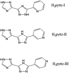
In fact, the organic moieties are crucial for the formation of the desired POM-based MOCs.10–12 In other words, the organic ligands, especially the N-donor ligands including bis(pyridlyl)-,13 bis(imidazole)-,14 bis(triazole)-,15 and bis(tetrazole)16 based derivatives, have become popular for the construction of coordination architecture and a variety of POM-based MOCs have been constructed.17 However, the POM-based MOCs constructed from the pyridyl-bis(triazole) ligands have been reported very limited.18–20 Herein, three pyridyl-bis(triazole), 3-(pyrid-2-yl)-5-(1H-1,2,4-triazol-3-yl)-1,2,4-triazolyl, 3-(pyrid-3-yl)-5-(1H-1,2,4-triazol-3-yl)-1,2,4-triazolyl, 3-(pyrid-4-yl)-5-(1H-1,2,4-triazol-3-yl)-1,2,4-triazolyl (hereafter noted as H2pyttz-I, H2pyttz-II and H2pyttz-III; see Scheme 1), were selected as the organic ligands to assemble with transition metal ions and POM anions. The ligands H2pyttz-I, H2pyttz-II and H2pyttz-III possess same bis(triazole) and pyridyl groups, but different pyridyl N-sites. The multiple N-donors and various pyridyl N-sites may play a positive role in the construction of diverse structures and stable POM-based frameworks. It is worth mentioning that the introduction of the pyridyl-bis(triazole) ligands into the Anderson-type POM-based MOCs were reported rarely.21 To our knowledge, the reports on the combination of pyridyl-bis(triazole) ligand with the [γ-Mo8O26]4− anions systems have not been found up to now. Additionally, the Co(II)/Ni(II) ions are chosen in this work, which exhibit versatile coordination geometries and may construct novel topological structures in POMs' system.22,23
In this paper, we reported the synthesis and characterization of five POM-based metal–organic complexes based on the three pyridyl-bis(triazole) ligands above and Anderson-type POMs/octamolybdate, that is, H{Co2(Hpyttz-I)2(H2O)6[CrMo6(OH)6O18]}·8H2O (1), {Co2(H2pyttz-I)2(H2O)4[TeMo6O24]}[Co(H2O)6]·3H2O (2), {Co3(Hpyttz-II)2](H2O)6[γ-Mo8O26}·10H2O (3), {Ni3(Hpyttz-II)2(H2O)6[γ-Mo8O26]}·10H2O (4) and {Ni3(Hpyttz-III)2(H2O)8[γ-Mo8O26]}·10H2O (5). In complex 3, the Anderson-type CrMo6 anions were in situ transformed to γ-Mo8O264− anions. The pH-dependent electrochemical behaviours and the bifunctional electrocatalytic properties of the title compounds have been reported.
Experimental
Materials and characterization
(NH4)6[TeMo6O24]·7H2O and Na3[CrMo6(OH6)O18]·8H2O were prepared according to a reference and confirmed by the IR spectrum.24 Other chemicals were of reagent grade and were used without further purification. FT-IR data were taken on a 60 Scimitar 2000 Near FT-IR Spectrometer by using KBr pellets in the range of 4000–500 cm−1. Thermogravimetric analyses (TGA) were carried out on a Pyris Diamond TG instrument under a flowing N2 atmosphere with a heating rate of 10 °C min−1. Powder X-ray diffraction data were recorded on an Ultima IV with D/teX Ultra diffractometer at 40 KV and 40 mA with Cu Kα (λ = 1.5406 Å) radiation. C, H, and N elemental analyses were carried out on a Perkin-Elmer 240C elemental analyser. A CHI 760 electrochemical workstation was used for the electrochemical experiments at room temperature.X-ray crystallography
Data for complexes 1–5 were performed on a Bruker SMART APEX II diffractometer with Mo Kα radiation (λ = 0.71069 Å) in ω and θ scan modes at 293 K. The structures were solved by direct methods, and non-H atoms were refined anisotropically by a least-squares method on F2 using the SHELXL-2014/7 package.25 For these complexes, the H atoms on C and N atoms were fixed in calculated positions. Crystal data as well as details of the data collection and refinement for the complexes are summarized in Table 1. Selected bond distances and angles are shown in Table S1.† CCDC contains the supplementary crystallographic data for this paper with deposition numbers 1586442–1586446 for 1–5.| a R1 = Σ||Fo| − |Fc||/Σ|Fo|.b wR2 = Σ[w(Fo2 − Fc2)2]/Σ[w(Fo2)2]1/2. | |||||
|---|---|---|---|---|---|
| Complex | 1 | 2 | 3 | 4 | 5 |
| Empirical formula | C18H47Co2CrMo6N14O38 | C18H40Co3TeMo6N14O37 | C18H44Co3Mo8N14O42 | C18H44Ni3Mo8N14O42 | C18H40Ni3Mo8N14O40 |
| Formula weight | 1810.17 | 1924.67 | 2072.98 | 2072.32 | 2036.29 |
| Crystal system | Triclinic | Triclinic | Triclinic | Triclinic | Triclinic |
| Space group | P![[1 with combining macron]](https://www.rsc.org/images/entities/char_0031_0304.gif) |
P![[1 with combining macron]](https://www.rsc.org/images/entities/char_0031_0304.gif) |
P![[1 with combining macron]](https://www.rsc.org/images/entities/char_0031_0304.gif) |
P![[1 with combining macron]](https://www.rsc.org/images/entities/char_0031_0304.gif) |
P![[1 with combining macron]](https://www.rsc.org/images/entities/char_0031_0304.gif) |
| a (Å) | 10.8960(17) | 10.9220(6) | 10.9150(4) | 10.8810(4) | 10.5650(7) |
| b (Å) | 11.1160(18) | 11.0630(5) | 12.4010(5) | 12.3290(5) | 11.4200(8) |
| c (Å) | 12.346(2) | 21.2740(10) | 12.5140(5) | 12.4580(5) | 12.1260(8) |
| α (°) | 106.385(3) | 100.8430(10) | 107.4950(10) | 106.8430(10) | 94.4490(10) |
| β (°) | 108.807(3) | 97.7960(10) | 113.3740(10) | 113.5710(10) | 114.0790(10) |
| γ (°) | 105.418(3) | 94.7390(10) | 102.0980(10) | 102.6890(10) | 95.0830(10) |
| V (Å3) | 1248.8(3) | 2485.8(2) | 1374.33(9) | 1354.63(9) | 1320.03(15) |
| Z | 1 | 2 | 1 | 1 | 1 |
| Dc (g cm−3) | 2.407 | 2.571 | 2.505 | 2.540 | 2.562 |
| μ (mm−1) | 2.430 | 3.130 | 2.758 | 2.922 | 2.994 |
| F (000) | 884 | 1854 | 1003 | 1006 | 986 |
| Reflection collected | 9053 | 18![[thin space (1/6-em)]](https://www.rsc.org/images/entities/char_2009.gif) 586 586 |
7755 | 10![[thin space (1/6-em)]](https://www.rsc.org/images/entities/char_2009.gif) 123 123 |
7580 |
| Unique reflections | 6322 | 12![[thin space (1/6-em)]](https://www.rsc.org/images/entities/char_2009.gif) 274 274 |
4967 | 6702 | 4668 |
| Parameters | 366 | 712 | 385 | 385 | 407 |
| Rint | 0.0215 | 0.0258 | 0.0387 | 0.0182 | 0.0122 |
| GOF | 1.017 | 0.989 | 1.008 | 1.029 | 1.045 |
| R1a [I > 2σ(I)] | 0.0390 | 0.0392 | 0.0441 | 0.0252 | 0.0214 |
| wR2b (all data) | 0.1011 | 0.0864 | 0.0988 | 0.0594 | 0.0529 |
Preparation of complexes 1–5
Preparation of complexes 1, 2 and 5 bulk-modified carbon paste electrode
Complex 1 bulk-modified carbon paste electrode (1-CPE) was fabricated by mixing 0.010 g of complex 1 and 0.10 g of graphite powder in an agate mortar for approximately 60 min to achieve a uniform mixture, and then 0.16 mL paraffin oil was added and stirred with a glass rod. The homogenized mixture was packed into a 3 mm inner diameter glass tube and the tube surface was wiped with weighing paper. The electrical contact was established with the copper wire through the back of the electrode. In a similar procedure, 2- and 5-CPEs were prepared with complexes 2 and 5, respectively. The bare CPE was prepared by similar process without any complexes.Results and discussion
Syntheses
In the process of hydrothermal synthesis, several factors can influence the formation of crystal phases, such as initial reactants, molar ratio, pH value, reaction time, temperature, etc. In this work, pH value of the reaction is crucial for the formation of the title complexes. Only at the pH value about 4.0 for 1, 3.9 for 2, 5.8 for 3, 4.2 for 4 and 2.8 for 5, the crystals can be obtained. There also are some precipitates in the final products. The crystals suitable for single-crystal structure determination were manually isolated, and washed with distilled water.Structural description
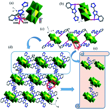
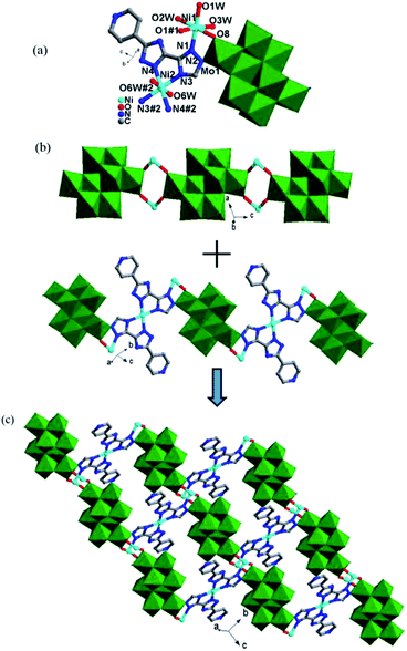
In complex 1, the Hpyttz-I ligand adopts a chelating mode to coordinate with one CoII ion and each CrMo6 polyoxoanion acts as a bidentate ligand that coordinating to two CoII ions by its two terminal oxygen atoms to form the binuclear unit (Fig. 1b). Interestingly, the discrete binuclear units are linked together through hydrogen bonding interactions between the oxygen atoms from the CrMo6 polyoxoanions and carbon atoms of the Hpyttz-I ligands [C(3)–H(3A)⋯O(10), 3.2540 Å] to form a 1D supramolecular chain (Fig. 1c).
The adjacent chains are further joined together by hydrogen bonding interactions [N(6)–H(6A)⋯O(8), 2.7150 Å] between the oxygen atoms of the CrMo6 polyoxoanions and the nitrogen atoms of the Hpyttz-I ligands to generate a 2D supramolecular network, as shown in Fig. 1d and e.
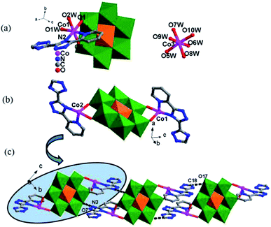
The H2pyttz-I ligand in 2 also adopts a bidentate chelating coordination mode and only coordinates to a Co1 ion. It should be noted that the coordination mode of H2pyttz-I in 2 is a slightly different from that in complex 1 (Table 2). In compound 1, Co ion is coordinated by the nitrogen atoms of the pyridine and the 1-position nitrogen atom of triazole, while in compound 2 is the nitrogen atom of the pyridine and the 4-position nitrogen atom of triazole. In addition, each TeMo6 anion exhibits a bidentate coordination mode through its four terminal oxygen atoms to coordinate with two Co1 ions to form a binuclear complex [Co2(H2pyttz-I)2(H2O)4 [TeMo6O24]]2− (Fig. 2b), which is different from 1. The discrete binuclear units are linked together through the hydrogen bonding interactions between the oxygen atoms of the TeMo6 polyoxoanions and the nitrogen atoms, carbon atoms of the H2pyttz-I ligands [N(3)–H(3A)⋯O(7), 2.7170 Å], [C(18)–H(18A)⋯O(17) 3.0100 Å] to form a 1D supramolecular chain (Fig. 2c).
 )
)
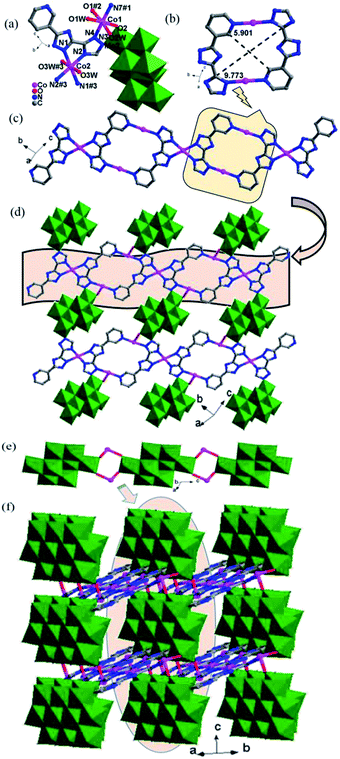
Each Hpyttz-II ligand provides five nitrogen atoms, in which the four nitrogen atoms of the bis-triazole coordinate to two Co ions (Co1, Co2) and one Mo atom of γ-Mo8O26 and the pyridyl nitrogen atom coordinates to Co2 ion, respectively (Table 2). Thus the Hpyttz-II ligands connect adjacent Co1 and Co2 ions forming a 1D Co-Hpyttz-II metal–organic chain (Fig. 3c), which contains the [Co2(Hpyttz-II)2] metal–organic loop with dimension of 5.901 × 9.773 Å2 (Fig. 3b).
In 3, the γ-Mo8O26 anions firstly provided two terminal oxygen atoms (O1) to coordinate with two Co2 ions from two adjacent 1D Co-Hpyttz-II chains, constructing a 2D network via Co2–O2 bonds (Fig. 3d). It should be noticed that a N-atom of the Hpyttz-II ligand coordinated to one γ-Mo8O26 anion through Mo–N bond, which consolidate the 2D network.
Finally, each γ-Mo8O26 anion provided four terminal atoms (O1, O2) to coordinate with Co2 ions to form a Co-γ-Mo8O26 inorganic chain (Fig. 3e), which extended the adjacent 2D layers into a 3D framework (Fig. 3f). The Ni1 is surrounded by three O atoms of three coordination water molecules, one N atom from the triazole of Hppty-III ligand, two O atoms from two [γ-Mo8O26]4-anions. The bond lengths around Ni1 ion are 2.000(3)–2.082(2) Å for Ni1–O, 2.054(3) Å for Ni1–N and the bond angles are 79.03(12)–180.0(13)° for O–Ni1–O and 79.03(12)–180.0(13)° for N–Ni1–O. Nevertheless, the Ni2 atom is coordinated by two O atoms of two coordination water molecules, four N atoms from triazole groups of two H2ppty-III ligands, which is similar to that of Co1 in complex 3. The bond lengths around Ni2 ion are 2.092(3) Å for Ni2–O, 2.055(3)–2.057(3) Å for Ni2–N and the bond angles are 180.000(12)° for O–Ni2–O, 79.03(12)–180.00(12)° for N–Ni2–N and 86.68(13)–93.32(13)° for N–Ni2–O, respectively.
In 5, each γ-Mo8O26 anions provided four terminal oxygen atoms to coordinate with four NiII ions to form a Ni-γ-Mo8O26 inorganic chain (Fig. 4b). Each Hpyttz-III ligand provides four nitrogen atoms of the bis-triazole groups to coordinate with two NiII ions and one Mo atom, in which the two nitrogen atoms (N3 and N4) adopts a bidentate chelating coordination mode to coordinate with Ni2 ion, the other two nitrogen atoms (N1 and N2) coordiante with the Ni1 ion and one Mo atom of γ-Mo8O26 respectively. Different from the Hpyttz-II in 3 and 4, the pyridyl N atom of the Hpyttz-III is noncoordinated, thus two Hpyttz-III ligands in 5 chelating a Ni2 ion, forming a [Ni(Hpyttz-III)2] mononuclear unit (Fig. 4c), which link the adjacent 1D Ni-γ-Mo8O26 inorganic chains conducing to the formation of the 2D network (Fig. 4d). It is worthy of mentioning that there also exist a Mo–N bond, which consolidate the 2D network.
Influences of the POM anions type and the rigid pyridyl-bis(triazole) ligands on the architectures
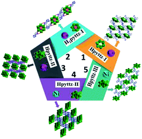
The title complexes represent the novel examples of POM-based MOCs constructed from three rigid pyridyl-bis(triazole) ligands and three different polyoxoanions, in which the polyanions and pyridyl-bis(triazole) ligands with different coordination sites show various coordination modes, exhibiting important effect on the whole structures (Table 2).In 1, the A-type Anderson anion CrMo6 was used, and each CrMo6 polyoxoanion acts as a bidentate ligand to coordinate with two CoII ions through its two terminal oxygen atoms, forming the binuclear unit. In 2, the B-type Anderson anion TeMo6 was employed, which provided four terminal oxygen atoms to coordinate with two Co1 ions, constructing a binuclear complex [Co2(H2pyttz-I)2(H2O)4[TeMo6O24]]2−. In addition, the coordination modes of the rigid pyridyl-bis(triazole) ligands in complexes 1 and 2 are slightly different (Table 2). As a result, 1 is 2D supramolecular network, while 2 is a 1D supramolecular chain, which indicate that POMs' type show an obvious influence on the final structures. In complexes 3 and 4, each Hpyttz-II ligand provides five nitrogen atoms, in which the four nitrogen atoms of the bis-triazole coordinate to two CoII/NiII ions and one Mo atom of γ-Mo8O26 and the pyridyl nitrogen atom coordinates to Co2/Ni2 ion, respectively. In complex 5, each Hpyttz-III ligand provides four nitrogen atoms from triazole groups, coordinating with Ni ions and one Mo atom of γ-Mo8O26. While the pyridyl N atom is noncoordinated. Thus, the Hpyttz-II and Hpyttz-III ligands with different coordination sites show completely different coordination modes, which finally result in various architectures: 3D frameworks for 3 and 4, 2D network for 5. Various structures of 1–5 confirmed the important effects of the rigid pyridyl-bis(triazole) ligands with different coordination sites (Scheme 2).
As discussed above, these results strongly suggest that the various coordination modes of the organic ligands and POM anions have assignable influences on the construction of the POM-based complexes. Therefore, an appropriate combination of different types of organic ligands and POMs may lead to the various structures with different dimensions.
IR spectra
The IR spectra of the title complexes are shown in Fig. S2.† The characteristic bands observed at 937, 906, 665 cm−1 for 1, 944, 887, 668 cm−1 for 2, 944, 843, 668 cm−1 for 3, 949, 837, 662 cm−1 for 4, 944, 856, 643 cm−1 for 5 are attributed to ν (Mo–Ot), ν (Mo–Ob–Mo), ν (Mo–Oc–Mo), respectively.26 Bands in the regions of 1657–1234 cm−1 for 1, 1657–1056 cm−1 for 2 and 1657–1025 cm−1 for 3, 1657–1022 cm−1 for 4 and 1632–1006 cm−1 for 5 are attributed to the H2pyttz-I, Hpyttz-II and Hppty-III, respectively.27 The bands around 3400 cm−1 can be ascribed to the water molecules.Powder X-ray diffraction (PXRD) and thermal analyses
The powder X-ray diffraction (PXRD) patterns for complexes 1−5 are presented in the Fig. S3 in the ESI.† The diffraction peaks of both simulated and experimental patterns match well, thus indicating that the phase purities of the compounds are good. The intensity differences may be owed to the different orientations of the crystals in the powder samples.28Thermogravimetric analyses (TGA) of the title complexes were performed under flowing N2 atmosphere with a heating rate of 10 °C min−1 from room temperature to 800 °C (Fig. S4†). The TG curve of 1 shows two distinct weight loss steps. The first weight loss step from room temperature to 393 °C corresponds to the loss of water molecules 12.93% (calcd 13.90%). The second weight loss at 395–800 °C is ascribed to the decomposition of organic molecules 24.67% (calcd 25.25%). For complex 2, the TGA gives an initial loss of 11.77% (calcd 12.16%) below 228 °C, representing the loss of water molecules. The second weight loss occurs in the temperature range of 230–800 °C, corresponding to the loss of H2pyttz-I ligands (calcd 22.14%, obsd 21.07%). For complex 3, the weight loss 13.23% attributed to the gradual release of water molecules is observed when the temperature is increased to 167 °C (calcd 13.89%), and the organic molecules decompose in the temperature range of 432 °C to 800 °C (calcd 19.77%, obsd 20.49%). For compound 4, the TG curve exhibits two steps of weight loss: the first loss is 13.33% from the room temperature to 273 °C corresponding to the loss of all water molecules (calcd 13.94%), and the second loss is 20.12% (calcd 19.46%) at 396−800 °C arising from the decomposition of the Hpyttz-II molecules. For 5, the first step starts from room temperature to 370 °C corresponding to the loss of lattice and coordination water molecules (calcd 10.83%, obsd 11.08%); and the second step begins from approximately 425 °C and is related to the decomposition of organic ligands (calcd 20.17%, obsd 22.38%).
Electrochemical behaviours of complexes 1-CPE, 2-CPE and 5-CPE
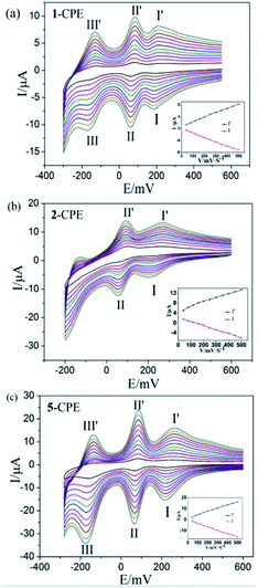
In order to investigate the electrochemical properties of these complexes, the title complexes bulk-modified CPEs are optimal choice, owing to their insolubility in water and classical solvents. Considering the electrochemical behaviors of complexes 3–5 are similar apart from some light potential shift, complexes 1, 2 and 5 were taken as the examples. The electrochemical behaviours of complex 1 bulk-modified carbon paste electrode (1-CPE) in 0.1 M H2SO4 + 0.5 M Na2SO4 aqueous solution at different scan rates are presented in Fig. 5a. The 1-CPE displays three pairs of reversible redox peaks in the potential range of +550 to −300 mV and the mean peak potentials E1/2 = (Epa + Epc)/2 are 225 mV (I–I′), 73 mV (II–II′) and −143 mV (III–III′) at 40 mV s−1, which belong to the three consecutive two-electron redox processes of Mo centres of CrMo6 polyanions.29 The 2-CPE displays two pairs of reversible redox peaks in the potential range of +600 to −200 mV (Fig. 5b), and the mean peak potentials E1/2 = (Epa + Epc)/2 are 239 mV (I–I′) and 79 mV (II–II′) at 40 mV s−1, which correspond to two consecutive two-electron redox processes of Mo centres of TeMo6 polyoxoanions in complex 2.30 The 5-CPE also displays three pairs of reversible redox peaks in the potential range of +600 to −300 mV and the mean peak potentials E1/2 = (Epa + Epc)/2 are 244 mV (I–I′), 76 mV (II–II′) and −144 mV (III–III′) at 40 mV s−1 (Fig. 5c), which can be attributed to three consecutive two-electron redox processes of Mo centers in the Mo8O26 polyoxoanion.31,32 The peak potentials change gradually with the increasing of scan rates. In the scan rate range of 40–500 mV s−1, all the cathodic peak potentials shift toward the negative direction gradually, while the corresponding anodic peak potentials shift to the positive direction with the increase of the scan rates. As shown in the inset of Fig. 5, the peak currents are proportional to the scan rates up to 500 mV s−1, showing that the redox processes of 1-, 2-, and 5-CPEs are surface-controlled.It is well known that some POMs usually show electrocatalytic activities in the reduction process of nitrite, bromate, hydrogen peroxide and other substances in aqueous solution.31 In this work, the electrocatalytic activities of the 1-, 2- and 5-CPEs toward the reduction of bromate/hydrogen peroxide and the oxidation of ascorbic acid (AA) were investigated.
As shown in Fig. 6a–c and 7a–c, with the addition of hydrogen peroxide or bromate, the reduction peak currents of 1-, 2- and 5-CPEs increase gradually and the corresponding oxidation peak currents gradually decrease, which indicate that the 1-, 2- and 5-CPEs possess good electrocatalytic activity toward the reduction of hydrogen peroxide and bromate and the reduction products are H2O and Br−, respectively.33,34 As can be seen from Fig. 8a–c, with the addition of AA, the oxidation peak currents of 1-, 2- and 5-CPEs gradually increase, which suggests that 1-, 2- and 5-CPEs present excellent electrocatalytic activities for the oxidation of AA and the oxidation product is g-lactone.35 Alternatively, no obvious voltammetric response is observed at the bare CPE in the presence of hydrogen peroxide, bromate or AA in the same potential range, suggesting that the reduction of bromate/hydrogen peroxide and the oxidation of AA is electrocatalyzed by the reduced species of the POM anions in the title complexes.
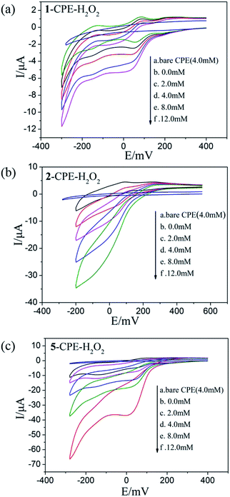 | ||
| Fig. 6 Cyclic voltammograms of the 1-CPE, 2-CPE and 5-CPE in 0.1 M H2SO4 + 0.5 M Na2SO4 aqueous solution containing 0.0–12.0 mM H2O2. | ||
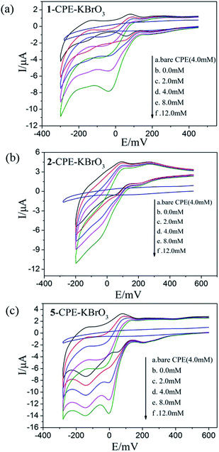 | ||
| Fig. 7 Cyclic voltammograms of the 1-CPE, 2-CPE and 5-CPE in 0.1 M H2SO4 + 0.5 M Na2SO4 aqueous solution containing 0.0–12.0 mM KBrO3. | ||
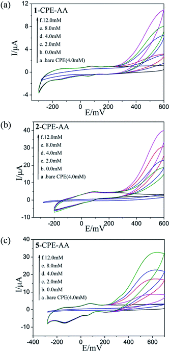 | ||
| Fig. 8 Cyclic voltammograms of the 1-CPE, 2-CPE and 5-CPE in 0.1 M H2SO4 + 0.5 M Na2SO4 aqueous solution containing 0.0–12.0 mM AA. | ||
In order to probe the influence of the variation of acidity on the electrochemical response of the 5-CPE, H2SO4/Na2SO4 aqueous solution was used to adjust the pH values of the medium. The results indicated that electrochemical behavior of 5-CPE is pH dependent, as shown in Fig. 9. With the pH value increase from 1.0 to 4.0, the redox waves shift gradually to the negative potential direction and the peak current intensity gradually decrease. The 1- and 2-CPEs also show similar electrochemical responses (Fig. S5†). The successive redox processes versus pH for the 1-, 2- and 5-CPEs are shown in Fig. 9b and S6.† Good linearity in the pH range from 1.0 to 4.0 was obtained, which indicated that the 1-, 2- and 5-CPEs may be used as a kind of pH potential sensor. Such an electrochemical behaviors of 1-, 2-, and 5-CPEs is consistent with the previous reports, which highlights the significance of protons in the electrochemistry of POMs.36 The results indicate that the title complexes may be used as pH sensor materials and have potential application prospects.
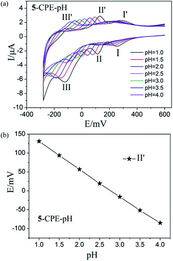 | ||
| Fig. 9 (a) Cyclic voltammograms of 5-CPE at different pH values (Scan rate: 40 mV s−1); (b) Variation of anodic peak potentials of the MoVI-based wave (II′) with different pH for 5-CPE. | ||
Conclusions
In conclusion, we present five new Anderson-type POM and octamolybdate-based metal–organic complexes with different rigid pyridyl-bis(triazole) ligands, POMs ions and transition metals CoII/NiII. The organic ligands with different coordination sites and the polyoxoanions with various coordination modes play important roles in tuning the dimensionalities and structures of the title complexes. Complexes 1–5 show highly electrochemical sensitive of pH in the range from 1.0 to 4.0. In addition, the title complexes exhibit excellently electrocatalytic activities for the reduction of BrO3−/H2O2 and the oxidation of AA, which may be potential candidates as multifunctional materials.Conflicts of interest
There are no conflicts to declare.Acknowledgements
The supports of the National Natural Science Foundation of China (No. 21471021, 21671025, 21501013 and 21401010), Program for Distinguished Professor of Liaoning Province (No. 2015399) and Key Laboratory of Polyoxometalate Science of Ministry of Education are gratefully acknowledged.Notes and references
- (a) D. L. Long, E. Burkholder and L. Cronin, Chem. Soc. Rev., 2007, 36, 105 RSC; (b) J. T. Rhule, C. L. Hill and D. A. Judd, Chem. Rev., 1998, 98, 327 CrossRef PubMed; (c) N. Mizuno and M. Misono, Chem. Rev., 1998, 98, 199 CrossRef PubMed; (d) M. T. Pope and A. Müller, Angew. Chem., Int. Ed. Engl., 1991, 30, 34 CrossRef; (e) Y. Hou, L. Zakharov and M. Nyman, J. Am. Chem. Soc., 2013, 135, 16651 CrossRef PubMed; (f) A. Merca, S. Garai, H. Bögge, E. Haupt, A. Ghosh, X. Lépez, J. Poblet, F. Averseng, M. Che and A. Müller, Angew. Chem., Int. Ed., 2013, 52, 11765 CrossRef PubMed; (g) Y. Zhu, P. C. Yin, F. P. Xiao, D. Li, E. Bitterlich, Z. C. Xiao, J. Zhang, J. Hao, T. B. Liu, Y. Wang and Y. G. Wei, J. Am. Chem. Soc., 2013, 135, 17155 CrossRef PubMed; (h) J. Zhou, J. W. Zhao, Q. Wei, J. Zhang and G. Y. Yang, J. Am. Chem. Soc., 2014, 136, 5065 CrossRef PubMed; (i) Z. G. Jiang, K. Shi, Y. M. Lin and Q. M. Wang, Chem. Commun., 2014, 50, 2353 RSC; (j) U. Kortz, A. Müller, J. vanSlageren, J. Schnack, N. S. Dalal and M. Dressel, Coord. Chem. Rev., 2009, 253, 2315 CrossRef.
- (a) C. Qin, X. L. Wang, L. Yuan and E. B. Wang, Cryst. Growth Des., 2008, 8, 2093 CrossRef; (b) X. L. Wang, C. Qin, E. B. Wang and Z. M. Su, Chem. Commun., 2007, 41, 4245 RSC.
- (a) X. J. Dui, W. B. Yang, X. Y. Wu, X. F. Kuang, J. Z. Liao, R. M. Yu and C. Z. Lu, Dalton Trans., 2015, 44, 9496 RSC; (b) J. Z. Liao, H. L. Zhang, S. S. Wang, J. P. Yong, X. Y. Wu, R. M. Yu and C. Z. Lu, Inorg. Chem., 2015, 54, 4345 CrossRef PubMed.
- (a) Z. Peng, Angew. Chem., Int. Ed., 2004, 43, 930 CrossRef PubMed; (b) A. K. C. Gallegos, M. L. Cant'u, N. C. Pastor and P. G. Romero, Adv. Funct. Mater., 2005, 15, 1125 CrossRef; (c) M. Carraro, M. Gardan, G. Scorrano, E. Drioli, E. Fontananova and M. Bonchio, Chem. Commun., 2006, 0, 4533 RSC; (d) M. Bonchio, M. Carraro, M. Gardan, G. Scorrano, E. Drioli and E. Fontananova, Top. Catal., 2006, 40, 133 CrossRef; (e) J. M. C. Juan and E. Coronado, Coord. Chem. Rev., 1999, 193, 361 CrossRef; (f) H. Lv, Y. V. Geletii, C. Zhao, J. W. Vickers, G. Zhu, Z. Luo, J. Song, T. Lian, D. G. Musaev and C. L. Hill, Chem. Soc. Rev., 2012, 41, 7572 RSC.
- (a) X. J. Yang, X. J. Feng, H. Q. Tan, H. Y. Zang, X. l. Wang, Y. H. Wang, E. B. Wang and Y. G. Li, J. Mater. Chem., 2016, 4, 3947 RSC; (b) Z. H. Pu, C. T. Zhang, I. S. Amiinu, W. Q. Li, L. Wu and S. C. Mu, Mater. Interfaces, 2017, 9, 16187 CrossRef PubMed.
- (a) M. Sadakane and E. Steckhan, Chem. Rev., 1998, 98, 219 CrossRef PubMed; (b) S. Mukhopadhyay, J. Debgupta, C. Singh, A. Kar and S. K. Das, Angew. Chem., Int. Ed., 2018, 130, 1936 CrossRef.
- C. J. Wang, T. T. Wang, Q. Lan, S. Yao, H. L. Wu, Y. Y. Zhou, Z. M. Zhang and E. B. Wang, RSC Adv., 2016, 6, 15513 RSC.
- (a) X. Ma, K. F. Song, J. Gao, P. J. Gong, H. L. Li, L. J. Chen and J. W. Zhao, Inorg. Chem. Commun., 2015, 60, 65 CrossRef; (b) J. Luo, X. Ma, L. J. Chen and J. W. Zhao, Inorg. Chem. Commun., 2015, 54, 25 CrossRef.
- S. Q. Liu, D. G. Kurth and D. Volkmer, Chem. Commun., 2002, 0, 976 RSC.
- J. X. Meng, Y. Lu, Y. G. Li, H. Fu and E. B. Wang, Cryst. Growth Des., 2009, 9, 4116 CrossRef.
- P. P. Zhang, J. Peng, H. J. Pang, J. Q. Sha, M. Zhu, D. D. Wang, M. G. Liu and Z. M. Su, Cryst. Growth Des., 2011, 11, 2736 CrossRef.
- X. L. Wang, H. L. Hu and A. X. Tian, Cryst. Growth Des., 2010, 10, 4786 CrossRef.
- B. K. Tripuramallu and S. K. Das, Cryst. Growth Des., 2013, 13, 2426 CrossRef.
- Y. Q. Lan, S. L. Li, X. L. Wang, K. Z. Shao, D. Y. Du, H. Y. Zang and Z. M. Su, Inorg. Chem., 2008, 47, 8179 CrossRef PubMed.
- J. Q. Sha, M. T. Li, J. W. Sun, Y. N. Zhang, P. F. Yan and G. M. Li, Dalton Trans., 2013, 42, 7803 RSC.
- X. L. Wang, H. L. Hu, G. C. Liu, H. Y. Lin and A. X. Tian, Chem. Commun., 2010, 46, 6485 RSC.
- X. L. Wang, J. J. Sun, H. Y. Lin, Z. H. Chang, A. X. Tian, G. C. Liu and X. Wang, Dalton Trans., 2016, 45, 2709 RSC.
- X. Y. Yang, T. Wei, J. S. Li, N. Sheng, P. P. Zhu, J. Q. Sha, T. Wang and Y. Q. Lan, Inorg. Chem., 2017, 56, 8311 CrossRef PubMed.
- P. P. Zhu, N. Sheng, G. D. Liu, J. Q. Sha and X. Y. Yang, Polyhedron, 2017, 131, 52 CrossRef.
- X. L. Wang, J. Luan, F. F. Sui, H. Y. Lin, G. C. Liu and C. Xu, Cryst. Growth Des., 2013, 13, 3561 CrossRef.
- X. L. Wang, J. J. Sun, H. Y. Lin, Z. H. Chang, G. C. Liu and X. Wang, CrystEngComm, 2017, 19, 3167 RSC.
- Y. Duan, J. M. Clemente-Juan, C. Giménez-Saiz and E. Coronado, Inorg. Chem., 2016, 55, 925 CrossRef PubMed.
- L. Zhang, L. Liu, C. Huang, X. Han, L. Guo, H. Xu, H. W. Hou and Y. T. Fan, Cryst. Growth Des., 2015, 15, 3426 CrossRef.
- (a) Z. X. Zhang, T. Murayama, M. Sadakane, H. Ariga, N. Yasuda, N. Sakaguchi, K. Asakura and W. Ueda, Nat. Commun., 2015, 6, 7731 CrossRef PubMed; (b) M. Filowitz, R. K. C. Ho, W. G. Klemperer and W. Shum, Inorg. Chem., 1979, 18, 93 CrossRef; (c) H. T. Evans, Acta Crystallogr., Sect. B: Struct. Crystallogr. Cryst. Chem., 1974, 30, 2095 CrossRef.
- G. M. Sheldrick, Acta Crystallogr., Sect. A: Found. Crystallogr., 2008, 64, 112 CrossRef PubMed.
- C. R. Deltcheff, M. Fournier, R. Franck and R. Thouvenot, Inorg. Chem., 1983, 22, 207 CrossRef.
- P. P. Zhu, L. J. Sun, N. Sheng, J. Q. Sha, G. D. Liu, L. Yu, H. B. Qiu and S. X. Li, Cryst. Growth Des., 2016, 16, 3215 CrossRef.
- A. Z. Tian, J. Ying, J. Peng, J. Q. Sha, H. J. Pang, P. P. Zhang, Y. Chen, M. Zhu and Z. M. Su, Cryst. Growth Des., 2008, 8, 3717 CrossRef.
- C. H. Gong, X. H. Zeng, C. H. Zhu, J. H. Shu, P. X. Xiao, X. Hao, L. C. Liu, J. Y. Zhang, Q. D. Zeng and J. L. Xie, RSC Adv., 2016, 6, 106248 RSC.
- S. M. Wang, W. L. Chen and E. B. Wang, J. Cluster Sci., 2010, 21, 133 CrossRef.
- (a) A. Dolbecq, P. Mialane, B. Keita and L. Nadjo, J. Mater. Chem., 2012, 22, 24509 RSC; (b) P. Wang, X. P. Wang and G. Y. Zhu, Electrochim. Acta, 2000, 46, 637 CrossRef.
- (a) P. Wang, X. P. Wang, Y. Yuan and G. Y. Zhu, J. Non-Cryst. Solids, 2000, 277, 22 CrossRef; (b) H. Y. Liu, H. Wu, J. F. Ma, Y. Y. Liu, J. Yang and J. C. Ma, Dalton Trans., 2011, 40, 602 RSC.
- J. Taraszewska, G. Rosłonek and W. Darlewski, J. Electroanal. Chem., 1994, 371, 223 CrossRef.
- L. D. Li, W. J. Li, C. Q. Sun and L. S. Li, Electroanalysis, 2002, 14, 368 CrossRef.
- P. Wang, X. P. Wang, X. Y. Jing and G. Y. Zhu, Anal. Chim. Acta, 2000, 424, 51 CrossRef.
- M. Ammam and E. B. Easton, Electrochim. Acta, 2011, 56, 2847 CrossRef.
Footnote |
| † Electronic supplementary information (ESI) available: IR Spectra, TG, and additional figures. CCDC 1586442–1586446. For ESI and crystallographic data in CIF or other electronic format see DOI: 10.1039/c8ra03277g |
| This journal is © The Royal Society of Chemistry 2018 |

