
 Open Access Article
 This Open Access Article is licensed under a Creative Commons Attribution-Non Commercial 3.0 Unported Licence
Mechanical behaviour and microstructural evolution of Ni-based single crystal alloys under shock loading†
Ben Li a,
Chao Donga,
Jingui Yu*ab,
Qiaoxin Zhang*a,
Hongyan Zhoua and
Rong Liua
a,
Chao Donga,
Jingui Yu*ab,
Qiaoxin Zhang*a,
Hongyan Zhoua and
Rong Liua
aSchool of Mechanical and Electronic Engineering, Wuhan University of Technology, Wuhan, 430070, P. R. China. E-mail: yujingui@whut.edu.cn; zhangqx@whut.edu.cn
bState Key Laboratory of Material Processing and Die & Mould Technology, Huazhong University of Science and Technology, Wuhan 430074, P. R. China
First published on 15th June 2018
Abstract
Engine turbine blades are subjected to high-temperature and high-speed fragment impacts during use, and the ability of the blades to resist shocks affects their reliability. At present, there are few studies on the ability to withstand shocks of Ni-based single crystal alloys, especially with regards to their mechanical behaviour and microstructural evolution under shock loading. The solutions to the above problems can further help us understand the mechanisms of the mechanical responses and microstructural evolution of Ni-based single crystal alloys under shock loading. Thus, we study the mechanical behaviour and microstructural evolution characteristics of Ni-based single crystal alloys with different crystal orientations under shock loading using molecular dynamics simulations. We find that the (001) phase interface has the strongest impediment ability due to its dislocation network structure and the expansion of dislocations, which lead to the greatest reinforcing effect on the matrix. The penetration force of the (001) phase interface is the greatest with fragment penetration. Moreover, the energy dissipation capacity of the (001) phase interface is the highest with fragment penetration because it has the strongest resistance to shock loading. The second highest is the (110) phase interface, and the minimum dissipation capacity comes from the (111) phase interface. This study has an important theoretical significance for the in-depth understanding of the failure mechanisms of Ni-based single crystal alloys under shock loading.
1. Introduction
If an engine is struck by an air-to-air missile,1–4 the turbine blades are damaged first. Due to the wide range of possible angles and speeds that an impact can come from and the wide range of fragment sizes that can impact a turbine blade, the degree of damage caused can vary widely. Under the shock of a fragment, turbine blades are mainly subjected to breakdown, fracture and severe distortion.5 Once the turbine blade is damaged over a large area, the engine can stop mid-air. To improve the ability of turbine blades to resist shock loading, to reduce the damage rate of turbine blades as much as possible, and to prolong the working time of the engine under the conditions where some turbine blades are damaged, tensile or shear tests under fault conditions are performed.6–8 Few studies, however, have focused on the shock loading conditions caused by high-temperature and high-speed fragments.Ni-based single-crystal alloys are the main materials used in advanced aero-engine turbine blades. The ability of the Ni-based single-crystal alloy to withstand fragment shock has a significant influence on a fighter plane’s viability. High-quality Ni-based single-crystal alloys enable the turbine blade to break without failure.9 This material can considerably prolong the working time of the engine if some turbine blades are damaged, which has significantly improved the survival rate of fighter pilots. Several recent studies have focused on the mechanical behaviour of Ni-based single-crystal alloys under microscopic tensile and shear conditions,10–13 but little information is available about the shock resistance of Ni-based single-crystal alloys. In particular, the mechanical behaviour and evolution of the crystallographic microstructure of different Ni-based single-crystal alloys in response to shock loading are poorly understood. The microstructure of Ni-based single-crystal alloys determines the macroscopic mechanical properties.14 Therefore, the mechanical properties and structural evolution of Ni-based single-crystal alloys with different crystal orientations must be studied under shock loading at a microscopic scale. This study is important for improving the manufacture of Ni-based single-crystal alloy materials.
2. Computational methods
Three methods are available for studying the micromechanical behaviour of Ni-based single-crystal alloys: computer simulation, experimental observation and theoretical analysis. At microscopic scales, classical continuum mechanics theory and related experimental methods are no longer suitable for the study of the material’s mechanical properties due to the size effect, quantum effect and surface effect. The dislocation emission, matrix yield and surface film rupture of matrix materials are difficult to observe at microscopic scales. Computer simulation technology can address these drawbacks. Molecular dynamics simulations are widely used for these applications and allow easy modelling and accurate calculations that are easy to intuitively carry out.15–18 This study uses molecular dynamics simulations. The embedded atom method (EAM) is used to simulate the microstructure evolution of Ni-based single-crystal alloys.19–21 Ni-based single-crystal alloys have face-centred cubic (fcc) structures that are well suited for studying using EAM methods. In this study, the potential function of a Ni–Al system was used to simulate the evolution of the microstructure under shock loading. The shock behaviour of Ni–Al alloys has been studied in literature20,21 using the potential function of Ni–Al. Accordingly, we studied the mechanical behaviour and microstructure evolution of Ni-based single crystal alloys under shock loading.EAM potential (E) is composed of two terms and can be expressed as
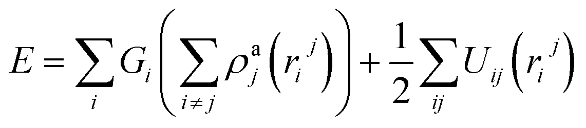 | (1) |
 | (2) |
 | (3) |
 | (4) |
Ni-based single-crystal alloys are distinguished from polycrystalline alloys via their special cubic structure, in which the γ′ phase and the γ phase are uniformly coherent. Molecular dynamics simulation models have been abstracted into three types, namely the sandwich model, the cube model and the mezzanine model. Among them, the mezzanine model has the highest computational efficiency, so we use the mezzanine model for our molecular dynamics simulation.
In the molecular dynamics simulation of Ni-based single-crystal alloys, the lattice constant of the upper γ phase Ni is 3.520 Å, and the lattice constant of the lower γ′ phase Ni3Al is 3.573 Å. Due to the difference in the lattice constants of the γ′ and γ phases, mismatches occur at the interfaces of the mezzanine model. The degree of mismatch has a significant influence on the simulation calculations. To mitigate the influence of interface mismatching on the calculation results, we use the coincidence-lattice method, which uses the following equation:
| naγ′ = (n + 1)aγ | (5) |
In eqn (5), the lattice constant of Ni3Al is aγ′ and the lattice constant of Ni is aγ. When n = 66, the cross-sectional areas of the lower γ′ matrix and the upper γ matrix are equal. Ni-based single-crystal alloys have strong anisotropy. In this simulation, three different crystal orientations of Ni-based single-crystal alloy simulation models were formulated. To simulate the mechanical response characteristics of the fragments injected into the turbine-blade material, the upper layer of the model was modelled as a Ni atom cluster with dimensions 67aγ × 67aγ × 16aγ and a lower layer of Ni3Al atoms with dimensions 66aγ′ × 66aγ′ × 16aγ′, where aγ = 0.352 nm, aγ′ = 0.3573 nm, and the dimensions of the box along the x, y, and z directions were 234.96 Å, 234.96 Å, and 70.01 Å. The fragments were modelled as rigid spherical bodies and the fragment radius was set to 3 nm.
Molecular dynamics simulations of the (001) phase interface model of Ni-based single-crystal alloys have been studied previously.22–26 However, all of them are focused on tension and shear forces. The first model established in this study is the (001) phase interface model. The (001) phase interface model’s x, y and z axes are parallel to the [100], [010] and [001] crystal directions in the γ/γ′ phase matrix, respectively. The second model is the (110) phase interface. The x, y and z axes of this model are parallel to the [0![[1 with combining macron]](https://www.rsc.org/images/entities/char_0031_0304.gif) 0], [100] and [011] crystal orientations of the γ/γ′ phase matrix, respectively. Third, the (111) phase interface model’s x, y and z axes are parallel to the [11
0], [100] and [011] crystal orientations of the γ/γ′ phase matrix, respectively. Third, the (111) phase interface model’s x, y and z axes are parallel to the [11![[2 with combining macron]](https://www.rsc.org/images/entities/char_0032_0304.gif) ], [10] and [111] crystal orientations, respectively.
], [10] and [111] crystal orientations, respectively.
The atoms of the three different phase interface models are set to free states. The atomic motion in the model obeys Newton’s second law and the model adopts periodic boundary conditions in the x- and y-directions. Following previous experience,27–29 the shock velocity of the fragments is set to 10![[thin space (1/6-em)]](https://www.rsc.org/images/entities/char_2009.gif) 000 m s−1, the simulation time step is set to 2 × 10⁻¹⁵ s, and the maximum penetration depth is set to 3.7 nm in the present simulation.
000 m s−1, the simulation time step is set to 2 × 10⁻¹⁵ s, and the maximum penetration depth is set to 3.7 nm in the present simulation.
3. Results and discussion
The basic model is shown in Fig. 1a. The system was relaxed before the MD simulations; the number of relaxation steps was 1.0 × 10⁵ steps. After the three phase interface models of (001), (110) and (111) were fully relaxed in a Nose/Hoover thermal bath, the energy and stress of the models were at a minimum and the system was in a relatively stable state. After the three models were fully relaxed, they formed different phase dislocation network structures, as shown in Fig. 1b–d. Fig. 1b shows the dislocation network of the (111) phase interface model. Its dislocation network is triangular and has faces. Fig. 1c shows the dislocation network of the (110) phase interface model, and its dislocation network is in a # shape. The #-shaped dislocation network comprises linear dislocations. Fig. 1d shows the square dislocation network of the (001) phase interface model. The square phase interface dislocation network comprises four linear dislocations. The square dislocations are formed via crystal mismatches between the upper and lower layers of the model. The results of this study are consistent with those reported in the literature.30 The (001), (110) and (111) interface models have different kinds of dislocation network structure, which show clear anisotropy.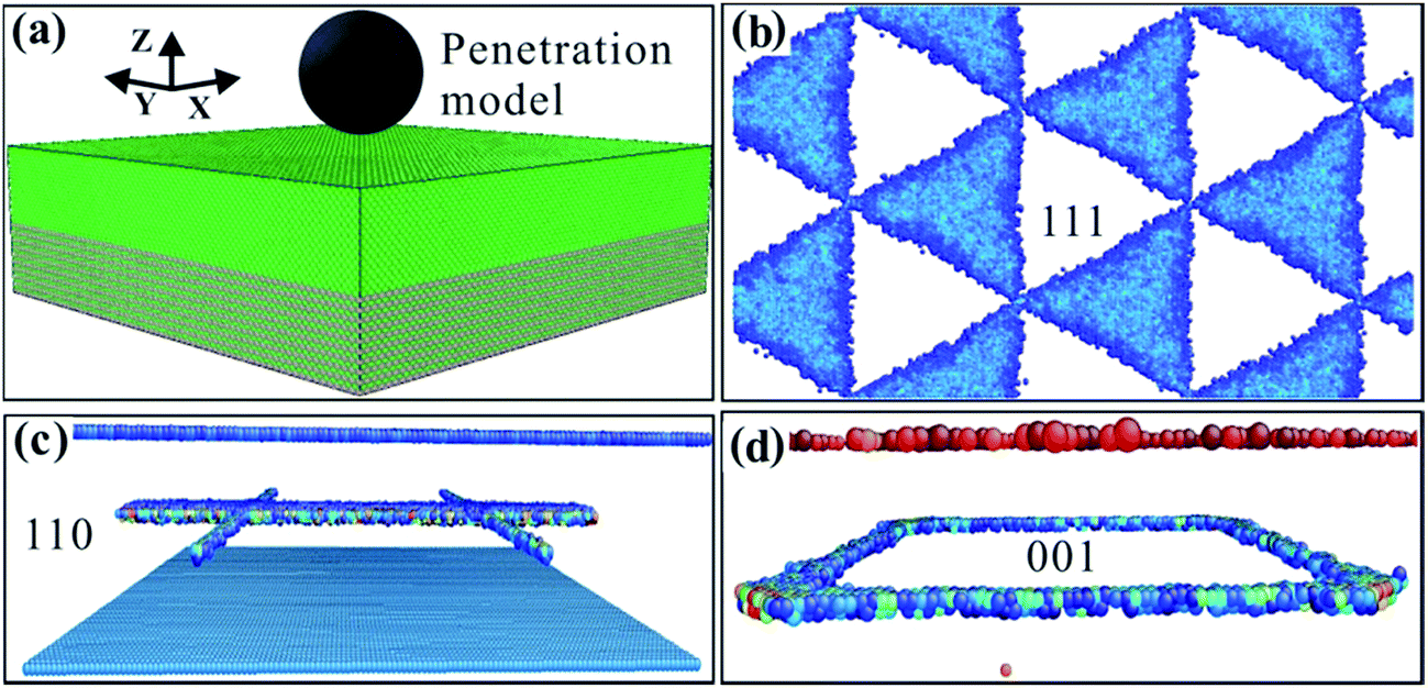 | ||
| Fig. 1 (a) Calculation model. (b) Interface dislocation network of the (111) model. (c) Interface dislocation network of the (110) model. (d) Interface dislocation network of the (001) model. | ||
The intrusion of high-temperature and high-speed fragments into the turbine blade is affected by the internal resistance of the material. Different crystal-oriented Ni-based single-crystal alloys have different resistances to fragment invasion; therefore, the penetration force required for the fragment to reach the same depth differs. The required penetration force was plotted against penetration depth for the three different phase interface models. As shown in Fig. 2, the penetration force required for fragment invasion increases with penetration depth. The overall trend of the depth–force curve of the (111) phase interface is relatively gradual and this curve is generally lower than the curves of the (110) and (001) phase interface materials. The force required to penetrate the (111) interface increases slowly with the penetration depth, and the penetration force only reaches 2513 nN when the penetration depth is 3.7 nm. The (110) phase interface curve shows a small deviation from the curves of the (111) and (001) phase interface materials before the penetration depth reaches 1.2 nm, and there is a partial overlap of these curves. This overlap occurs because the anisotropy is muted by the surface effects of the material matrix during the initial stage of fragment penetration. Once the penetration depth exceeds 1.2 nm, the value of the required penetration force dramatically increases. When the penetration depth reaches 3.7 nm, the required penetration force is 5382 nN, which is much higher than the penetration force required for the (111) phase interface under the same penetration depth conditions, showing obvious anisotropy. The penetration depth–penetration force curve for the (001) phase is generally above the curves of the (110) and (111) phases. The penetration force needs to increase rapidly after the penetration depth exceeds 1.2 nm, and the growth rate for this phase is the fastest of the three depth–penetration force curves. When the penetration depth reaches 3.7 nm, the required penetration force is 6875 nN. In terms of the results of this study, it is most difficult for the fragments to penetrate the (001) interface model, followed by the (110) model and then the (111) model.
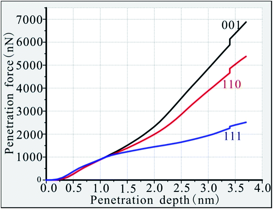 | ||
| Fig. 2 Penetration depth–penetration force curves of the three different models. | ||
To fully calculate the ability of the different crystalline Ni-based single-crystal alloy materials to resist deformation caused by impact loading from fragments, it is necessary to analyse the nano-hardness of the materials.31–33 According to Newton’s third law, every force is accompanied by an equal reaction force. The impact load on the substrate can be calculated according to the magnitude of the penetration force. The nano-hardness of the material can then be calculated under impact loading conditions, as shown in Fig. 3a. As seen in Fig. 3a, the penetration depth–hardness curve of the (001) interface is above the other curves and the hardness of this material is about 15 GPa. Due to size effects, the penetration depth-hardness curves of three different crystalline materials were very close and crossed while the penetration depth was less than 1.2 nm. The penetration depth–hardness curve of the (110) interface is between those of the (001) and (111) interfaces, and the hardness is 11 GPa, which is equal to the hardness of the (001) interface at a penetration depth of around 0.6 nm. The penetration depth–hardness curve of the (111) phase interface model is below the curves of the (001) and (110) models, and the hardness is about 5.5 GPa, which is almost equal to the hardness of the (001) phase interface at a penetration depth of around 0.2 nm. The (111) interface is much less hard than the interfaces of the (001) and (110) phases. From the calculation results, the nano-hardness of the (001) phase interface is the largest, indicating that the deformation resistance to fragment impacting load for this phase interface is the strongest, followed by the (110) phase interface, which means the (111) phase interface is the weakest.
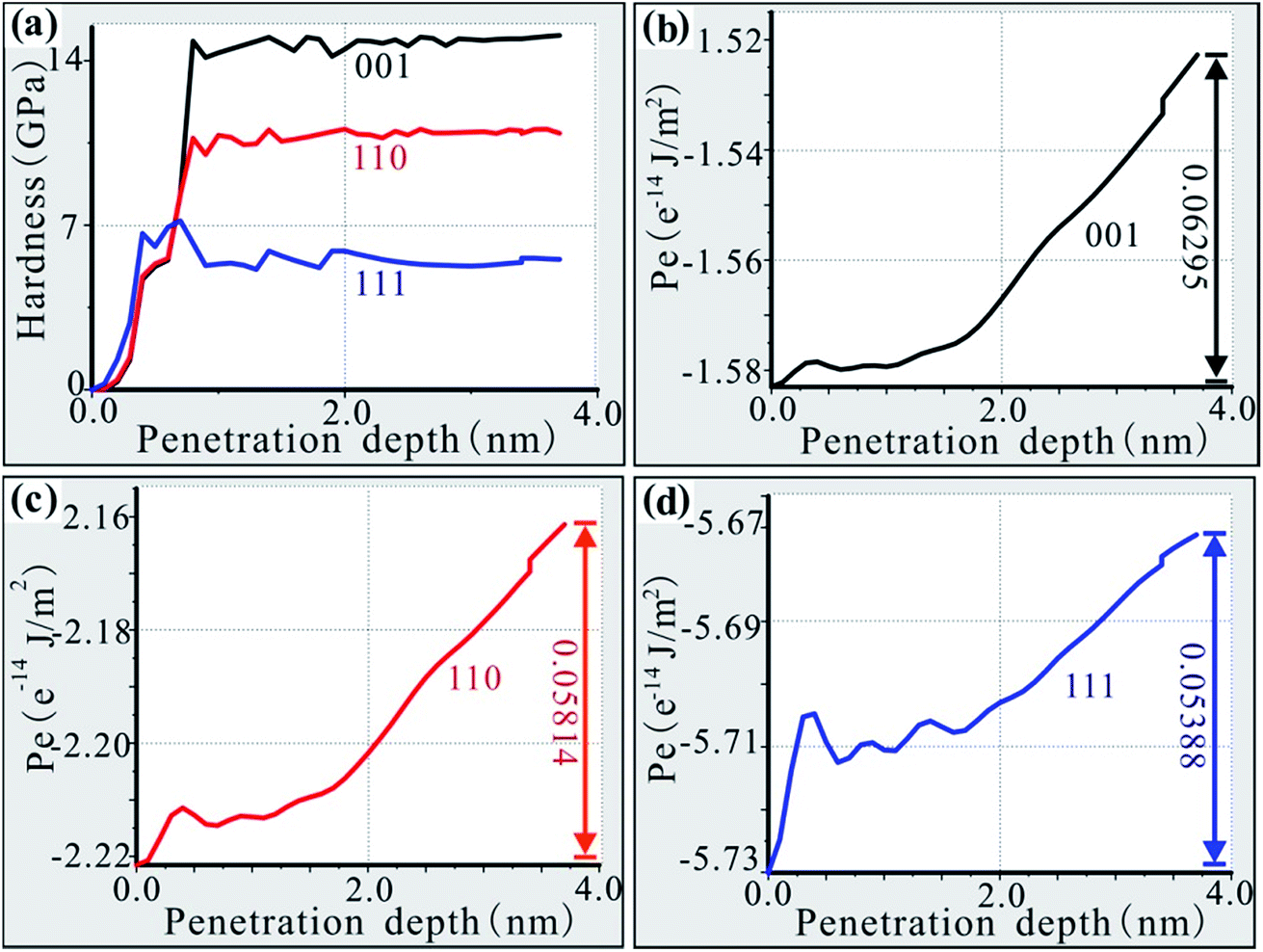 | ||
| Fig. 3 (a) Nano-hardness of the three different models. (b) Penetration depth–energy curve of the (001) model. (c) Penetration depth–energy curve of the (110) model. (d) Penetration depth–energy curve of the (111) model. | ||
The penetration depth–energy curve of the (001) phase interface is shown in Fig. 3b. It can be seen from Fig. 3b that the initial energy of the (001) phase interface model system is −1.58299 × 10⁻¹⁴ J m−2. In the initial stage of fragment intrusion, the calculation model is affected by the impact of the fragments and accumulates elastic potential energy. In the fragment impact process, the new surface that is formed needs to absorb energy, so the energy of the model system begins to increase. For a penetration depth of less than 0.4 nm, the energy of the model system continues to increase up to −1.57844 × 10⁻¹⁴ J m−2. At this stage, the energy of the model system increases by 4.55 × 10⁻¹⁷ J m−2. When the penetration depth reaches 0.5 nm, the energy released from the destruction of the old surface is greater than the energy absorbed by the new surface. The energy of the system decreases from −1.57844 × 10⁻¹⁴ J m−2 to −1.57924 × 10⁻¹⁴ J m−2 and transitions smoothly until the penetration depth reaches 1.0 nm. For penetration depths greater than 1.0 nm, the energy of the model system increases continuously. When the penetration depth is between 1.0 nm and 1.6 nm, the energy of the model system increases slowly. For penetration depths greater than 1.6 nm, the energy of the model system increases rapidly. This trend shows that the formation of a new surface absorbs more energy from this moment so that the fragments penetrate less deeply into the material. When the fragments reach the interior of the material at 3.7 nm, the energy of the model system increases to −1.52004 × 10⁻¹⁴ J m−2. Over the entire impact process up to a depth of 3.7 nm, the model system absorbs an energy of 6.295 × 10⁻¹⁶ J m−2. From the perspective of energy conservation, fragments will lose at least 6.295 × 10⁻¹⁶ J m−2 of energy.
The penetration depth–energy curve of the (110) phase interface is shown in Fig. 3c. The initial system energy of the (110) phase interface model is −2.22052 × 10⁻¹⁴ J m−2. In a similar way to the (001) phase interface model, in the initial stage of fragment intrusion, the penetration is an elastic compression so the energy of the model system increases until the penetration depth reaches 0.4 nm. At this point, the energy of the model system increases to −2.21141 × 10⁻¹⁴ J m−2, i.e. an increase of 1.011 × 10⁻¹⁶ J m−2. Compared with the (001) phase model, the (110) model absorbs more energy in the elastic phase. When the penetration depth is 0.5 nm, the old surface is destroyed and energy is released. The system energy decreases from −2.21141 × 10⁻¹⁴ J m−2 to −2.21269 × 10⁻¹⁴ J m−2. From this point onwards, a smooth transition takes place until the penetration depth reaches 1.2 nm. When the penetration depth is between 1.2 nm and 1.8 nm, the energy of the model system slowly increases. When the penetration depth is greater than 1.8 nm, the energy of the model system increases rapidly, which indicates that the formation of a new surface needs more energy to be absorbed from this moment, and it is more difficult for the fragment to penetrate into the material. Eventually, the energy of the model system increases to −2.16238 × 10⁻¹⁴ J m−2 when the fragments invade the interior of the material at 3.7 nm. The model system absorbs 5.814 × 10⁻¹⁶ J m−2 of energy overall. Compared with the (001) phase interface model, the calculated energy loss from the material is relatively small, indicating that high-temperature and high-speed fragments can easily penetrate the (110) phase interface.
The penetration depth–energy curve of the (111) interface is shown in Fig. 3d. The initial system energy of the (111) phase interface model is −5.73004 × 10⁻¹⁴ J m−2. In a similar way to the (001) and (110) interface models, the material compresses elastically up to a penetration depth of 0.4 nm. The energy of the model system increases by 2.534 × 10⁻¹⁶ J m−2 during this stage. Compared with the (001) and (110) phase interface models, the energy absorbed by the elastic phase is the largest, indicating that the (111) phase interface is more elastic. When the penetration depth reaches 0.5 nm, the old surface is destroyed and energy is released, so the system energy decreases from −5.70470 × 10⁻¹⁴ J m−2 to −5.70920 × 10⁻¹⁴ J m−2. Then, the curve starts to oscillate until the penetration depth reaches 1.6 nm, which is different from what happens in the (001) and (110) phase interface models. After the penetration depth reaches 1.6 nm, the energy of the model system increases rapidly. Eventually, the model system energy increases to −5.67616 × 10⁻¹⁴ J m−2 once the fragment has invaded the interior of the material at 3.7 nm. The model system absorbs 5.388 × 10⁻¹⁶ J m−2 of energy overall. The (111) interface is the weakest against fragment penetration.
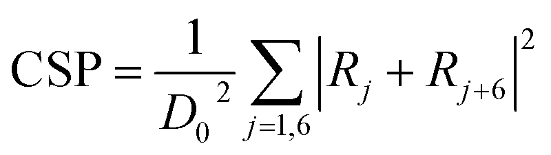
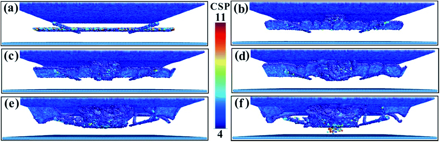
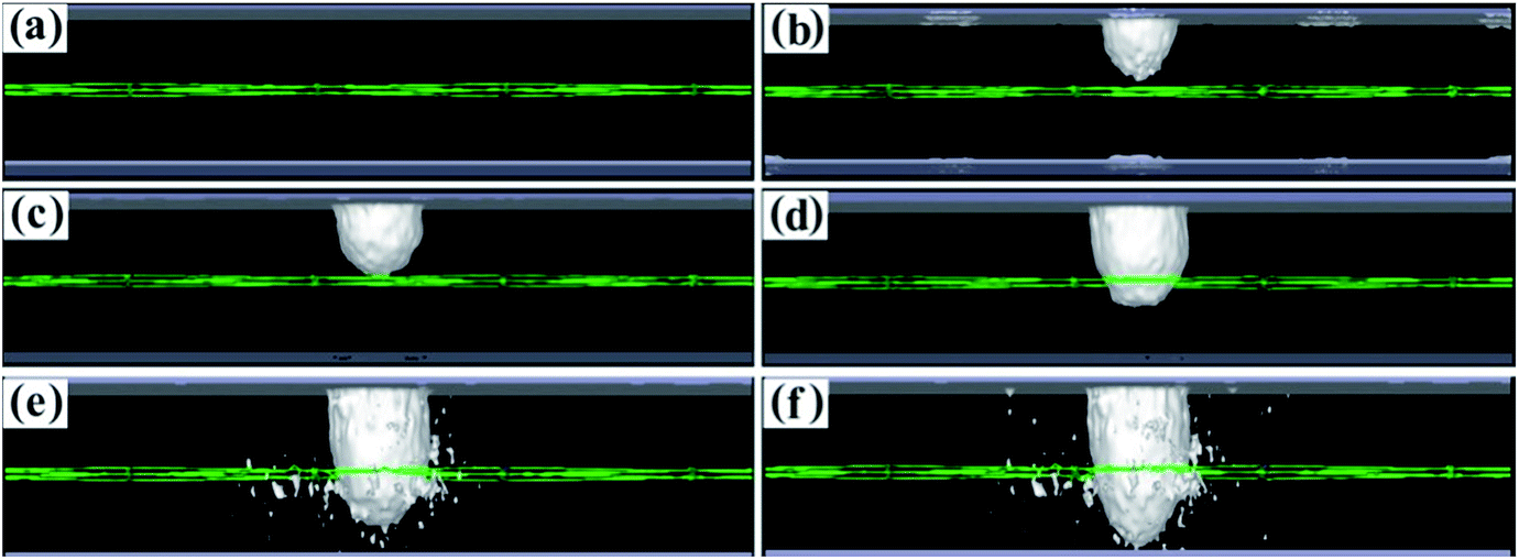
To fully study the microstructure evolution characteristics of Ni-based single-crystal alloys under impact loading conditions, the internal defects of the crystal structure must be analysed. For this purpose, CSP value maps of the models are extracted using molecular dynamics simulation calculations. For the purpose of analysis and comparison, the range of the CSP values for the different phase interface models are set from 4 to 11. Fig. 4 shows the CSP values of the (001) phase interface model. As shown in Fig. 4a, immediately after the fragment strikes the material and when the penetration depth reaches only 0.1 nm, the surface of the model is only destroyed partially and the dislocation does not have time to expand further. Square dislocations at the interface remain regular and neat. Once the penetration depth has reached 1 nm (Fig. 4b), the dislocations have expanded into the interior of the γ phase. A tapered dislocation cluster is generated directly below the impact surface of the fragment on the model surface. The dislocations grow as the fragment invades, and when the penetration depth reaches 1.5 nm, the dislocations expand to the interface and the dislocation density increases significantly (Fig. 4c). Affected by the effects of a high-speed fragment impact, dislocations continue to expand in the material. The square dislocation network at the interface begins to distort and the linear dislocation line widens (Fig. 4d). As the depth of penetration increases, the dislocation density also increases. However, the dislocation does not enter the γ′ phase. The interface dislocation network was distorted but did not break until the penetration depth reached 3.7 nm (Fig. 4e and f).
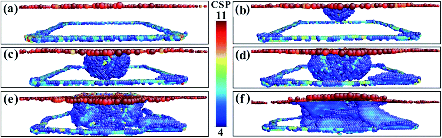 | ||
| Fig. 4 The CSP values for the (001) model with different penetration depths. (a) 0.1 nm. (b) 1.0 nm. (c) 1.5 nm. (d) 1.8 nm. (e) 2.0 nm. (f) 3.7 nm. | ||
The CSP values for the (110) phase interface model are shown in Fig. 5. In Fig. 5a, the #-shaped phase interface dislocation network is clearly visible. When the penetration depth reaches 0.5 nm (Fig. 5b), regular facet dislocations occur, which is clearly different from the behaviour of the (001) phase interface material. As the depth of penetration continues to increase, face-angle dislocations continue to grow (Fig. 5c and d). When the penetration depth increases to 1.8 nm, the original regular face-angle dislocation begins to deform and distort until it disappears, and the dislocations break through the phase interface and obstruct the entry into the γ′ phase (Fig. 5e). As the depth of penetration continues to increase, the dislocation density increases, and the dislocation slip becomes very complicated. When the penetration depth has reached 3.7 nm, some of the dislocations have spread to the underside of the γ′ phase (Fig. 5f). However, linear dislocations in the interface dislocation network remain relatively intact.
 | ||
| Fig. 5 The CSP values for the (110) model with different penetration depths. (a) 0.1 nm. (b) 0.5 nm. (c) 1.5 nm. (d) 1.8 nm. (e) 2.0 nm. (f) 3.7 nm. | ||
The CSP values of the (111) phase interface model are shown in Fig. 6. The triangular phase interface dislocation network is clearly visible in Fig. 6a. As the penetration depth increases, dislocations continue to appear and expand around the penetration location, dislocation density increases, and the final triangular interface dislocation network fails to prevent dislocations from entering the γ′ phase (Fig. 6b–d). The dislocations of the square dislocation network of the (001) phase interface model are the most hindered from passing from the γ phase into the γ′ phase and have the greatest strengthening effect on the matrix, followed by the dislocations of the (110) model and then the (111) model.
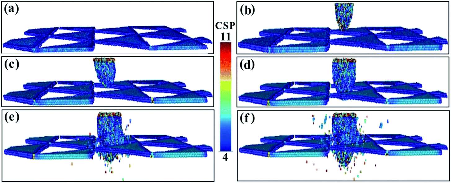 | ||
| Fig. 6 The CSP values for the (111) model with different penetration depths. (a) 0.1 nm. (b) 0.5 nm. (c) 1.5 nm. (d) 1.8 nm. (e) 2.0 nm. (f) 3.7 nm. | ||
To study the variation of the dislocations under impact loading conditions in more detail, dislocation diagrams were prepared by combining dislocation calculation methods. Fig. 7 shows the dislocation lines of the (001) phase interface model. In Fig. 7a, the square dislocation line of the calculation model can be clearly seen. As the fragment begins to penetrate the calculation model, many dislocation lines are generated directly below the penetration position (Fig. 7b). As the penetration depth increases, the linear dislocations of the square dislocation lines become roughened by the impact load, the dislocation density directly below the penetration position increases, and the dislocation lines expand to the periphery (Fig. 7c). Once the penetration depth increased to 3.5 nm, the dislocation line expanded to the interface (Fig. 7d and e), but did not break through the interface dislocation network that blocks entry into the γ′ phase (see the movies in the ESI†). Once the penetration depth reached 3.7 nm, the dislocation network in the square interface underwent a large distortion but did not disappear, and the dislocation line did not break through the interfacial dislocation network into the γ′ phase (Fig. 7f). This shows that the square dislocation network of the (001) phase interface model is very resistant to dislocation propagation. Combining this with the results of the CSP values, we can see that the interfacial dislocation network of the (001) phase interface model has the greatest reinforcing effect on the matrix structure. In this case, fragmentation is most hampered and penetration requires more energy.
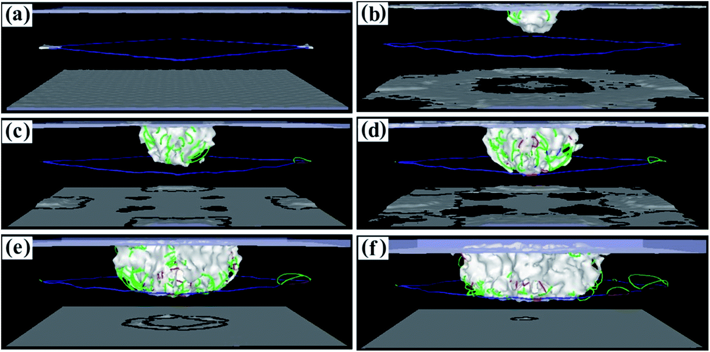 | ||
| Fig. 7 Dislocation line graphs with different penetration depths of the (001) model. (a) 0.1 nm. (b) 1.0 nm. (c) 1.5 nm. (d) 2.0 nm. (e) 3.5 nm. (f) 3.7 nm. | ||
The dislocation lines of the (110) phase interface model are shown in Fig. 8, and its unique facet dislocation line is shown in Fig. 8a and b. Under the influence of the shock loading from the fragment, the dislocation line of the face angles continued to grow, and the dislocation line immediately below the penetration position of the fragment expanded downward (Fig. 8c). When the penetration depth reaches 2.0 nm, the dislocation line at the face angle stops growing and begins to distort and the dislocation line just below the penetration position breaks through the barrier of the interface dislocation network into the γ′ phase (Fig. 8d). As the penetration depth increases further, dislocations in the γ′ phase continue to expand downwards and the dislocation line at the face angle area begins to disappear gradually (Fig. 8e). When the penetration depth reaches 3.7 nm, a small part of the dislocation line expands to the bottom of the γ′ phase (Fig. 8f). Compared with the dislocation line motion of the (001) phase interface model, the interfacial dislocation network of the (110) phase interface model is weaker than that of the (001) model and has a relatively small reinforcing effect on the substrate. Therefore, it is relatively easy for fragments to penetrate the (110) interface and the energy required for penetration is relatively small.
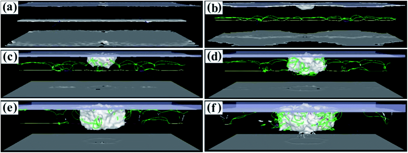 | ||
| Fig. 8 Dislocation line graphs with different penetration depths of the (110) model. (a) 0.1 nm. (b) 0.5 nm. (c) 1.5 nm. (d) 2.0 nm. (e) 3.5 nm. (f) 3.7 nm. | ||
The dislocation lines of the (111) phase interface model are shown in Fig. 9. The dislocation line motion characteristics of the (111) phase interface model are clearly different from those of the (001) and (110) models, as shown in Fig. 9a–f. When the penetration depth reaches 1.0 nm, the dislocation line breaks through the interfacial dislocation network to enter the γ′ phase (Fig. 9c). When the penetration depth reaches 2.0 nm, a small part of the dislocation line enters the bottom of the γ′ phase (Fig. 9d). When the penetration depth reaches 3.7 nm, a lot of dislocation lines enter the bottom of the γ′ phase (Fig. 9e and f). Compared with the dislocation line motion of the (001) and (110) interface models, the interface dislocation network of the (111) interface model allows for the most dislocation propagation and has the weakest reinforcing effect on the substrate. Therefore, fragments most easily penetrate the (111) interface, and the energy required for penetration is also the smallest.
 | ||
| Fig. 9 Dislocation line graphs with different penetration depths of the (111) model. (a) 0.1 nm. (b) 0.5 nm. (c) 1.0 nm. (d) 1.5 nm. (e) 2.0 nm. (f) 3.7 nm. | ||
4. Conclusions
In this paper, the mechanical behaviour and microstructure evolution of Ni-based single crystal alloys with different crystal orientations under impact loading are studied using molecular dynamics simulations. The results show that the mechanical behaviour anisotropy of Ni-based single crystal alloys under the impact load of high-temperature and high-speed fragments is obvious, which is of great theoretical significance for understanding the failure mechanism of turbine blades of an Ni-based single crystal alloy under an impact load. The results of the study are summarized in the following paragraph.The dislocations cannot break through the interface dislocation network and are prevented from passing from the γ phase into the γ′ phase at the (001) phase interface. However, lots of dislocations break through the interface and the dislocation network hinders their entry into the γ′ phase at the (110) and (111) phase interfaces. Thus, the (001) interface model’s square dislocation network structure is the strongest hindrance to the dislocations entering the γ′ phase, which has the greatest strengthening effect on the matrix. This is followed by that of the (110) model, meaning the dislocation network structure of the (111) model is the weakest hindrance. As can be seen from the penetration force required by high-temperature and high-speed fragments to penetrate the material, the dislocation network structure of the (001) phase interface is the strongest hindrance to the dislocations from the γ phase entering the γ′ phase. Thus, penetrating the (001) phase interface requires the maximum penetration force, followed by penetrating the (110) phase interface, and the (111) phase interface requires the weakest force. The energy dissipation capacity of the (001) phase interface is the highest with fragment penetration because it has the strongest resistance to shock loading, the second highest is that of the (110) phase interface, and the energy dissipation capacity is the minimum for the (111) phase interface.
Conflicts of interest
There are no conflicts to declare.Acknowledgements
This work was supported by the National Natural Science Foundation of China (No. 51210008), the Fundamental Research Funds for the Central Universities (WUT: 2018IVA023) and the Open Foundation of State Key Laboratory of Materials Processing and Die & Mould Technology, Huazhong University of Science and Technology (No. P2019-020).References
- G. A. Rao and S. P. Mahulikar, Aerosp. Sci. Technol., 2005, 9, 701–712 CrossRef.
- D. Gapiński, I. Krzysztofik and Z. Koruba, Mech. Syst. Signal Process., 2018, 98, 802–815 CrossRef.
- T. H. Kim, J. H. Kim and P. Kim, Int. J. Aeronaut. Space Sci., 2017, 18, 757–766 Search PubMed.
- H. Buschek, Contr. Eng. Pract., 2003, 11, 551–558 CrossRef.
- D. Shi, C. Wang, X. Yang and S. Li, Fatigue Fract. Eng. Mater. Struct., 2017, 853, 498–502 Search PubMed.
- J. Zhou, H. Z. Huang and Z. Peng, J. Mech. Sci. Technol., 2017, 31, 4203–4213 CrossRef.
- P. A. Kulkarni, W. Hu, A. S. Dhoble and P. M. Padole, Adv. Mech. Eng., 2017, 9, 1–26 Search PubMed.
- R. M. N. Fleury and D. Nowell, Int. J. Fatigue, 2017, 105C, 27–33 CrossRef.
- A. Sawant and S. Tin, Scr. Mater., 2008, 58, 275–278 CrossRef.
- P. Li, B. M. Zhou, Y. Z. Zhou, J. G. Li, T. Jin, X. F. Sun and Z. F. Zhang, Philos. Mag., 2014, 94, 2426–2446 CrossRef.
- J. Lapin, T. Pelachov́ and M. Gebura, Kovove Mater., 2012, 50, 379–386 Search PubMed.
- Z. F. Yue and Z. Z. Lu, Acta Metall. Sin., 2002, 38, 809–813 Search PubMed.
- S. Tian, X. Ding, Z. Guo and J. Xie, Rare Met. Mater. Eng., 2014, 594, 7–16 Search PubMed.
- K. Asari and K. Kakehi, J. Jpn. Inst. Met., 2010, 74, 820–825 CrossRef.
- Y. Zhang, S. Jiang, X. Zhu and Y. Zhao, Phys. E, 2017, 90, 90–97 CrossRef.
- Y. Zhang and S. Jiang, Metals, 2017, 7, 432–442 CrossRef.
- Y. Zhang, S. Jiang, X. Zhu and Y. Zhao, Phys. Lett. A, 2016, 380, 2757–2761 CrossRef.
- Y. Z. Chen, L. C. Zhou, W. F. He, Y. Sun, Y. H. Li, Y. Jiao and S. H. Luo, Eur. Phys. J. B, 2017, 90, 16–22 CrossRef.
- T. Li, Z. C. Wang, Y. R. Duan, J. Li and H. Li, RSC Adv., 2017, 7, 53509–53515 RSC.
- M. J. Cherukara, T. C. Germann, E. M. Kober and A. Strachan, J. Phys. Chem. C, 2016, 120, 6804–6813 CrossRef.
- M. J. Cherukara, T. C. Germann, E. M. Kober and A. Strachan, J. Phys. Chem. C, 2014, 118, 26377–26386 CrossRef.
- E. Zarkadoula, G. Samolyuk and W. J. Weber, J. Alloys Compd., 2017, 700, 106–112 CrossRef.
- J. Yu, S. Zhang, Q. Zhang, R. Liu, M. Tang and X. Li, RSC Adv., 2016, 6, 107748–107758 RSC.
- J. Yu, Q. Zhang, Z. Yue, R. Liu, M. Tang and X. Li, Mater. Express, 2015, 5, 343–350 CrossRef.
- R. Muñoz-Moreno, V. D. Divya, S. L. Driver, O. M. D. M. Messe, T. Illston, S. Baker, M. A. Carpenter and H. J. Stone, Mater. Sci. Eng., A, 2016, 674, 529–539 CrossRef.
- G. Wang, J. Liu, J. Liu, T. Jin, X. Sun, X. Sun and Z. Hu, J. Mater. Sci. Technol., 2016, 32, 1003–1007 CrossRef.
- S. Zhang, L. U. Yuzhang, W. Zheng, J. Peng, G. Xie, G. Zhang and J. Shen, Mater. Rev., 2016, 30, 6–9 Search PubMed.
- H. L. Yao, X. Z. Hu and G. J. Yang, J. Nanosci. Nanotechnol., 2018, 18, 4121–4126 CrossRef PubMed.
- J. Wang, W. G. Guo, Y. Su, P. Zhou and K. Yuan, Mech. Mater., 2016, 94, 79–90 CrossRef.
- Q. Liu, Y. X. Yao and L. Zhou, Key Eng. Mater., 2009, 392, 267–270 Search PubMed.
- N. D. Bakhteyeva, N. I. Vinogradova, S. N. Petrova, V. P. Pilyugin and V. A. Sazonova, Phys. Met. Metallogr., 1998, 85, 97–104 Search PubMed.
- J. Li, F. Li, J. Dong, Z. Yuan and S. Zhang, J. Nanomater., 2015, 2015, 1–15 Search PubMed.
- R. R. Shen, V. Strom and P. Efsing, Mater. Sci. Eng., A, 2016, 674, 171–177 CrossRef.
Footnote |
| † Electronic supplementary information (ESI) available. See DOI: 10.1039/c8ra03129k |
| This journal is © The Royal Society of Chemistry 2018 |