
 Open Access Article
 This Open Access Article is licensed under a Creative Commons Attribution-Non Commercial 3.0 Unported Licence
Synthesis of heterometallic metal–organic frameworks and their performance as electrocatalyst for CO2 reduction†
Maite Perfecto-Irigaray a,
Jonathan Albo*b,
Garikoitz Beobide*a,
Oscar Castilloa,
Angel Irabienb and
Sonia Pérez-Yáñezac
a,
Jonathan Albo*b,
Garikoitz Beobide*a,
Oscar Castilloa,
Angel Irabienb and
Sonia Pérez-Yáñezac
aDepartamento de Química Inorgánica, Facultad de Ciencia y Tecnología, Universidad del País Vasco/Euskal Herriko Unibertsitatea, UPV/EHU, Apartado 644, E-48080 Bilbao, Spain. E-mail: garikoitz.beobide@ehu.eus
bDepartment of Chemical & Biomolecular Engineering, University of Cantabria (UC), Avda. Los Castros, 39005, Santander, Spain. E-mail: jonathan.albo@unican.es
cDepartamento de Química Inorgánica, Facultad de Farmacia, Universidad del País Vasco/Euskal Herriko Unibertsitatea, UPV/EHU, E-01006 Vitoria-Gasteiz, Spain
First published on 8th June 2018
Abstract
Herein we report the solventless synthesis and doping of the benchmark HKUST-1(Cu) as a facile route to afford heterometallic metal–organic frameworks (MOFs) having proficient behavior as electrocatalytic materials in the reduction of carbon dioxide. Zn(II), Ru(III) and Pd(II) were selected as doping metals (MD) with the aim of partially replacing the Cu(II) atoms of the pristine structure to afford HKUST-1(Cu,MD) type materials. Apart from the high yield and good crystallinity of the obtained materials, the extremely high reagent concentration that the reaction conditions imply makes it feasible to control dopant loading in all cases. Prepared samples were processed as electrodes and assembled in a continuous flow filter-press electrochemical cell. Faraday efficiency to methanol and ethanol at Ru(III)-based electrodes resulted in activity as high as 47.2%, although the activity of the material decayed with time. The interplay of the dopant metal and copper(II), and the long-term performance are also discussed.
Introduction
Porous coordination polymers (PCPs), most commonly known as metal–organic frameworks (MOFs), have led to a myriad of research works, which up to now have been in the spotlight of the scientific communities researching chemistry, physics, materials science and other bordering research areas.1 MOFs are hybrid crystalline materials containing inorganic nodes, isolated metals or metal clusters and organic linkers that form metal–organic coordination networks with potentially accessible voids. The nature and porosity of these compounds, together with their high specific surface areas (up to ca. 7000 m2 g−1),2 make them ideal materials for a wide range of potential uses including gas storage, separation and catalysis. In particular, applications in energy technologies such as fuel cells, supercapacitors and catalytic conversion have made them objects of extensive study, industrial-scale production and application in the last few years.3Moreover, the excessive atmospheric concentration of greenhouse gases means it is mandatory to reduce the anthropogenic CO2 emissions, which has become a critical challenge for sustainable development. Among the different approaches to solve this issue, CO2 capture and subsequent storage (CCS) technologies stand out, in which MOFs appear to be appealing materials due to their high surface area-to-weight ratio and ability to systematically modulate the pore dimensions and surface chemistry.4 More recently, a related alternative, carbon capture and utilization (CCU), has started to attract attention worldwide because it can turn waste CO2 emissions into valuable products such as chemicals and fuels, while at the same time contributing to climate change mitigation.5 Regarding the different methodologies employed for CCU, CO2 electrochemical conversion appears to be a promising strategy, providing products which are strongly dependent on catalyst materials and the reaction medium.6,7
In this sense, transition metals and their compounds, such as metal complexes, have been widely evaluated for the electroreduction of CO2. This is probably because these metals have vacant orbitals and active d electrons, which are believed to be able to energetically facilitate the bonding between the metal and CO2 (i.e. adduct formation) and the desorption of the reduction products.8 Copper has been demonstrated to be one of the most promising transition metals for obtaining hydrocarbons and alcohols at high reaction rates. However, elemental copper generates a range of reaction products, and the selectivity of each product tends to be low.9 For this reason, other Cu-based materials have also been tested to electrocatalytically reduce CO2, among which copper oxide based electrodes have exhibited the most prominent performance yielding methanol with high selectivity and current efficiency.10,11 It is also remarkable that the combination of copper with other electroactive metals improves the selectivity of the process.
Despite MOFs being extensively studied, only a handful of research works have assessed the electrocatalytic potential of MOFs to transform CO2 into added value chemicals, such as formic acid, CO + H2, and oxalic acid.12 In this regard, in a previous work,13 we concluded that Cu-based metal–organic porous materials with unsaturated coordination positions exposed on the pore surface are preferred to enhance the performance of the CO2 electroreduction to alcohols. Specifically, among the different tested metal–organic materials the ubiquitous HKUST-1 microporous MOF, supported in gas diffusion electrodes (GDEs), rendered the best results in terms of reaction rates and Faraday efficiencies.
In the present work, we first set the objective of assessing the aptness of a solventless synthesis route to afford heterometallic MOFs by doping of the benchmark HKUST-1(Cu), and secondly to evaluate the performance of these materials into the electrocatalytic conversion of CO2. Zn(II), Ru(III) and Pd(II) have been selected as dopant metals (MD), due to both their compatibility to suit the metal site and their recognized catalytic activity (Ru(III), Pd(II)) or stabilizing properties in long-term runs (Zn(II)).8 The powdered material was thoroughly characterized to study the doping process and then each doped-MOF was processed as a gas diffusion electrode. These MOF-GDEs were preliminary characterized through cyclic-voltammetry analyses, and then tested in the electrocatalytic reduction of CO2 using a continuous filter-press electrochemical cell.
Experimental
Synthesis of Cu/M/BTC MOFs
All of the chemicals were of reagent grade and were used as commercially obtained.Doped HKUST-1(Cu,MD) samples were prepared by modifying a synthetic procedure described for the solventless synthesis of pristine homometallic HKUST-1(Cu).14 In the general procedure, corresponding amounts of Cu(OAc)2·H2O (OAc: acetate), dopant metal (MD) source (Zn(OAc)2·2H2O, RuCl3·xH2O, Pd(OAc)2) and trimesic acid (H3BTC: benzene-1,3,5-tricarboxilic acid, 0.40 mmol) to satisfy the stoichiometry of [(Cu1−xMDx)3(BTC)2]n (x = 0, 0.05, 0.10 and 0.20) were hand-grinded thoroughly to obtain a homogeneous mixture (see Table S1 of ESI†). The final mixture was sealed in a 2 mL glass ampule and heated to 120 °C using a heating rate of 2 °C min−1 in a conventional oven for 48 h. The products were washed with water and ethanol to remove unreacted reagents. Table 1 shows the sample coding and their respective MD![[thin space (1/6-em)]](https://www.rsc.org/images/entities/char_2009.gif) :Cu molar ratios. It should be noted that, in general, MD:Cu ratios of the products are below those set in the aforementioned reaction mixture (5:95, 10:90, 20:80). This is further discussed in the results and discussion section.
:Cu molar ratios. It should be noted that, in general, MD:Cu ratios of the products are below those set in the aforementioned reaction mixture (5:95, 10:90, 20:80). This is further discussed in the results and discussion section.
:MD atomic ratio of synthesized bimetallic HKUST-1(Cu,MD)
| MD | MD:Cu ratio |
Sample code | Yield (%) |
|---|---|---|---|
| — | 0:100 |
H_Cu | 90 |
| Zn | 5:95 |
H_Zn5 | 70 |
| 8:92 |
H_Zn8 | 88 | |
| 19:81 |
H_Zn19 | 75 | |
| Ru | 3:97 |
H_Ru3 | 86 |
| 7:93 |
H_Ru7 | 89 | |
| 10:90 |
H_Ru10 | 83 | |
| Pd | 3:97 |
H_Pd3 | 85 |
| 5:95 |
H_Pd5 | 79 | |
| 11:89 |
H_Pd11 | 77 |
Physical measurements
Powder X-ray diffraction (PXRD) measurements were performed on a Phillips X'PERT diffractometer (equipped with Cu-Kα radiation, λ = 1.5418 Å) over the range 5 < 2θ < 70° with a step size of 0.02°, a variable automatic divergence slit and an acquisition time of 2.5 s per step at 293 K. Indexation of the diffraction profiles was made by means of the FULLPROF program (pattern-matching analysis)15 on the basis of the space group and the cell parameters found in the Cambridge Structural Database (CSD)16 for the single crystal X-ray structure of HKUST-1 (CSD entry: UVIPIZ). Further details can be found in the ESI (Fig. S1†).X-ray fluorescence (XRF) measurements were made using the XDRL Fischerscope X-ray system at 50 KeV power, under a nickel filter and with a 0.1 dm collimator. Ruthenium containing samples were further analyzed using a SPECS X-ray photoemission spectrometer (XPS).
Scanning electron microscopy (SEM) studies were carried out on a JEOL JSM-7000F microscope operated at 10–20 kV and coupled with an energy dispersive X-ray spectrometer (EDX). Specimens were mounted on conductive carbon adhesive tabs and imaged after chromium sputter coating of 5 nm to make them conductive.
The permanent porosity was studied by means of the measurements of N2 adsorption isotherms at 77 K using a Quantachrome Autosorb-iQ-MP analyzer. All samples were dried under vacuum at 150 °C over 6 h to eliminate solvent guest molecules prior to measurements. The surface area values were obtained by the fittings of the adsorption data to the Brunauer–Emmett–Teller (BET) equation. In order to choose the appropriate pressure range and to avoid ambiguity when reporting the BET surface area of MOFs, we used the three consistency criteria proposed by Walton and Snurr: (1) the pressure range selected should have values of V(Po–P) increasing with P/Po. (2) The points used to calculate the BET surface area must be linear with an upward slope. (3) The line they form must have a positive y-intercept.17
Preparation of MOF-GDEs
The GDEs (A = 10 cm2) were prepared by airbrushing a catalytic ink onto a porous carbon paper type TGP-H-60 (Toray Inc.) as described in our previous study.18 The catalyst loading in the GDEs was kept at 1 mg cm−2. The catalytic ink was formed by a mixture of the synthesized HKUST-1(Cu,MD) as the electrocatalysts, Nafion® dispersion 5 wt% as the binder and isopropanol (IPA) as the vehicle, with a 70:30 catalyst/Nafion mass ratio and a 3% solids (catalyst + Nafion) percentage. The mixture was sonicated for 15 min before airbrushing onto the carbon papers and the resulting MOF-GDEs were dried and rinsed with deionised water before use.
Cyclic voltammetry characterization
The electrochemical behavior of the materials was evaluated by cyclic voltammetries with a MSTAT4 (Arbin Instruments) employing a conventional three electrode electrochemical cell. The current–voltage curves were obtained with a scan rate of 50 mV s−1 at potentials ranging from 0 to −2 V versus Ag/AgCl in a CO2 saturated 0.5 M KHCO3 aqueous solution as electrolyte. Portions of the MOF-based GDEs were used as working electrodes, while a glassy carbon and Ag/AgCl (sat. KCl) were used as the counter and reference electrode, respectively. Current density is expressed as the total current divided by the geometric surface area of the electrodes.Electrochemical cell and experimental conditions for CO2 reduction
The prepared MOF-GDEs were evaluated for the continuous electrocatalytic reduction of CO2 using a filter-press electrochemical cell (Micro Flow Cell, ElectroCell A/S) system as described elsewhere.18 A Nafion 117 cation exchange membrane was used to separate the cathode and anode compartments. The MOF-GDEs were employed together with a platinized titanium electrode as the anode and a Ag/AgCl (sat. KCl) reference electrode was assembled close to the cathode. The cathode side of the reactor was fed with CO2 gas (99.99%) with a flow/area of Qg/A = 10 mL min−1 cm−2. A 0.5 M KHCO3 aqueous solution was used as both the catholyte and anolyte, with a flow rate of Qe/A = 2 mL min−1 cm−2. In this study, the filter-press electrochemical system possesses three inputs (catholyte, anolyte and CO2 separately) and two outputs (catholyte-CO2 and anolyte), which makes the formation of a gas–solid–liquid interface possible for the electrocatalytic reduction of CO2 in the gas phase.18All the experiments were performed at galvanostatic conditions (j = 20 mA cm−2), using an AutoLab PGSTAT 302N potentiostat (Metrohm, Autolab B.V.).
These Qg/A, Qe/A and j conditions were previously found to be optimal for the CO2 reduction using copper(I) and copper(II) type electrocatalysts.18
The experimental time was 90 min, during which pseudo-stable conditions are ensured, according to our previous analyses.10,18 Liquid samples were taken every 15 min from the catholyte tank. To quantify the concentration of each product in the liquid phase, the samples were analyzed in duplicate in a headspace gas chromatograph (GCMS-QP2010, Ultra Shimadzu) equipped with a flame ionization detector (FID). Compounds were separated on a DB-Wax 30 m × 0.25 mm × 0.25 μm column, with an injection and detector temperature of 250 °C and 270 °C, respectively. Helium was used as a carrier gas at a flow rate of 50 mL min−1. The product concentration was averaged from at least three replicates (standard deviations below 12.8%).
The performance of the electrochemical process was evaluated by productivity, r (i.e. product obtained per unit of cathode area and time), and the Faraday efficiency, FE (i.e. selectivity of the reaction for the formation of the different products).
Results and discussion
This section addresses, firstly, the chemical and microstructural characterization of HKUST-1(Cu,MD) doped with Zn(II), Ru(III) and Pd(II), describing the dopant loadings, their distribution and their effect in the crystallinity and microporosity. Thereafter, the performance of HKUST-1(Cu,MD) type MOFs as cathode material is assessed by means of cyclic voltammetry analyses and continuous reaction in a filter-press electrochemical cell. Throughout the paper samples have been coded as H_MDX, in which MD corresponds to the dopant metal (Zn, Ru or Pd) and X affords the incorporated dopant content.Characterization of bimetallic Cu/M/BTC samples
Synthesized MOF samples were initially characterized by XRF and PXRD to analyze the dopant content and its influence in the HKUST-1 crystalline phase. Table S1† collates the amount of dopant (MD) added as a reagent in the synthesis mixture and the amount incorporated into the synthesis product. In this respect, the relative agreement between dopant content targets and amounts found in the HKUST-1 samples varies with dopant element. In the case of zinc, whose size and atomic number are the closest to copper, the amount of dopant incorporated is almost the same as that added in the reagent mixture. Ruthenium and palladium are less efficiently assimilated during the synthesis process, giving rise to dopant contents somewhat below the target values (Table 1). XPS measurements taken on H_Ru samples revealed the presence of chloride ions (Cl 2p 199.5 eV) which in turn confirms the presence of ruthenium(III). It should be noted that in this case the chloride ion is required to counteract the additional positive charge that implies the use of a trivalent metal. In addition, previous works have reported the solvothermal synthesis of mixed valence HKUST-1(RuII,RuIII) in which chloride acts as a counterion to balance the network charge.19 With regard to the reaction yields, they do not seem to be influenced by the type of dopant, reaching in all cases values comparable to those obtained for undoped HKUST-1 (H_Cu).As mentioned above, PXRD results confirmed the maintenance of the crystalline phase corresponding to HKUST-1, as the PXRD patterns of the doped samples are in good agreement with that of pristine HKUST-1. For comparative purposes, Fig. 1 and Table 2 gather the results of the profile fittings carried out on PXRD patterns of H_Cu and of samples with dopant content close to 10% (H_Zn8, H_Ru10 and H_Pd11).
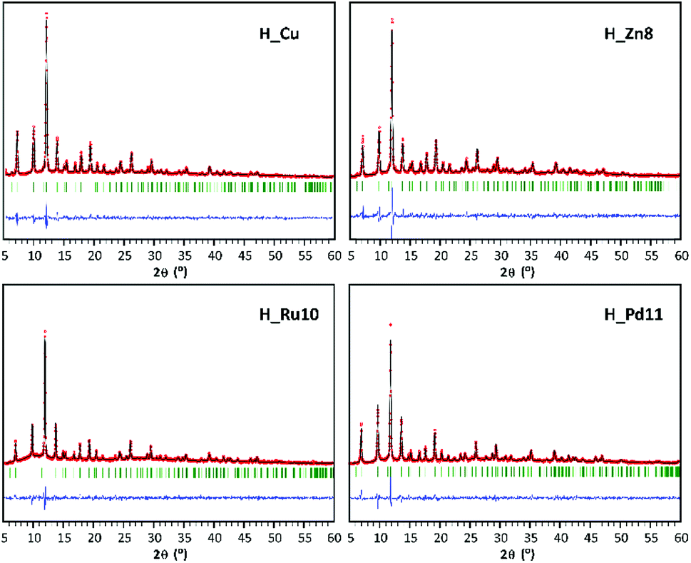 | ||
| Fig. 1 PXRD pattern-matching refinement plots for H_Cu, H_Zn8, H_Ru10, and H_Pd11 (green ticks: calculated reflections; red circles: experimental pattern; black line: simulated pattern; blue line: difference between patterns). | ||
| H_Cu | H_Zn8 | H_Ru10 | H_Pd11 | |
|---|---|---|---|---|
a  . . |
||||
| a (Å) | 26.283 (3) | 26.322 (4) | 26.345 (2) | 26.413 (3) |
| V (Å3) | 18156 (4) |
18238 (5) |
18285 (2) |
18428 (4) |
| Rb | 1.11 | 1.92 | 13.9 | 82.6 |
| Rp | 31.2 | 31.3 | 49.3 | 32.0 |
| χ2 | 2.27 | 2.33 | 1.45 | 1.77 |
The introduction of a doping element implies a slight increase of the cell parameter with respect to the homometallic H_Cu. This fact is attributable to the occurrence of longer M–Ocarboxylate coordination bond distances that implies the presence of the dopant in the paddle-wheel shaped dinuclear [M2(OOC)4] secondary building unit (SBU). In the case of Ru(III) and Pd(II), which are elements of the second transition series, their greater ionic radii values are consistent with an increase in coordination bond distances and cell parameters. On the contrary, Zn(II) exhibits a rather similar ionic radius to that of Cu(II), but the Jahn–Teller effect of Cu(II) (d9) implies shorter equatorial coordination distances than those found in analogous paddle-wheel shaped Zn(II) complexes.16 Despite the details described above, this indicates that the dopant is incorporated into the SBU of the MOF, but we cannot disregard that part of the dopant might also be appended as a defect in the surface of the framework.20 Accordingly, a reduction in the surface area and micropore volume might be expected, but a similar effect can also be attributed to the slight modifications of the synthetic conditions (such as a change in the starting reagents). When considering the PXRD analysis, it must be pointed out that despite the fact that solventless synthesis has been demonstrated to be a suitable procedure to incorporate dopants into MOFs,21 the method is quite sensitive to the hand-milling and heating procedure and as a result, it can produce some batches with some minor crystalline impurities in the products (Fig. S2 of ESI†).
The homogeneous nature of the samples and their crystallite size have been analyzed by means of SEM. SEM micrographs of the samples show polycrystalline samples (Fig. 2) with heaped sub-micrometric crystals. Such small sized particles can benefit the performance of the MOF-GDEs, as a greater external surface area of the dispersed catalytic material might favor the reaction kinetics.
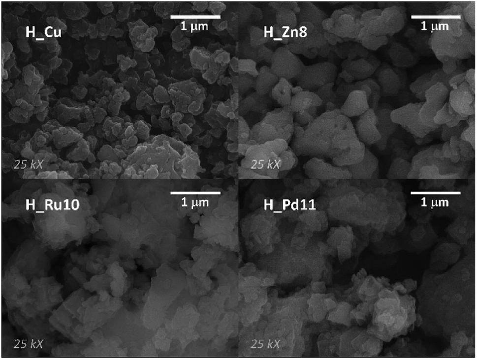 | ||
| Fig. 2 SEM micrographs (SEI mode) at 25000 magnifications of H_Cu, H_Zn8, H_Ru10, and H_Pd11. | ||
Furthermore, to assess the microstructural homogeneity of the samples, EDX spectra and backscattered electron images (BSE) were also collected during the SEM analysis. EDX data confirmed that mostly all measured samples (Fig. S3†) show a homogeneous distribution of the dopant metal throughout all of the material and only in the case of the H_Ru10 sample were some Ru(III) enriched areas observed. Accordingly, when BSE images of Pd(II) and Ru(III) samples with the highest dopant content (Fig. 3) are compared, the absence of contrast in H_Pd11 indicates a homogeneous distribution of Cu(II) and Pd(II), while lighter spots and darker broad particles in H_Ru10 correspond to more and less concentrated Ru(III) zones, respectively.
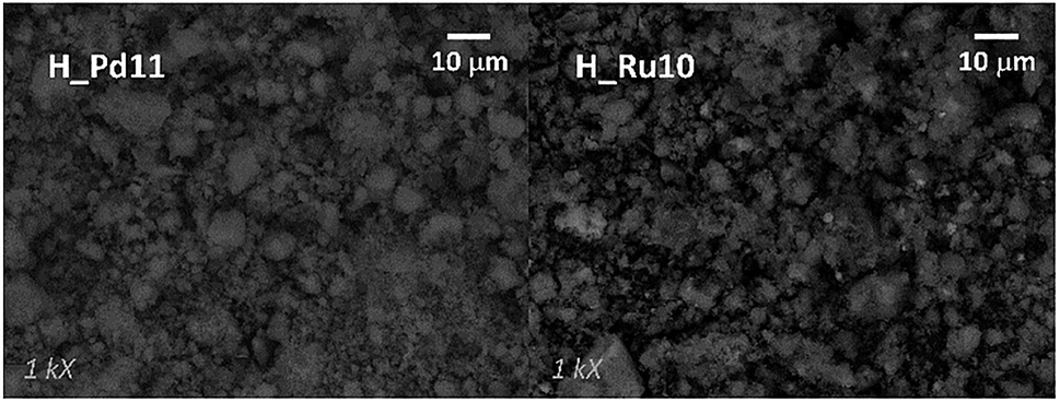 | ||
| Fig. 3 SEM micrographs (BSE mode) at 1000 magnifications of H_Pd11 and H_Ru10. | ||
For the microstructural analysis, N2 adsorption isotherms were measured at 77 K (Fig. 4). All of them can be defined, mainly, as type I isotherms according to the IUPAC classification22 with a marked knee (B-point) at P/Po values < 0.12, which is characteristic of the adsorptive behavior of microporous compounds. At intermediate pressures, the adsorption presents a certain monotonic rise followed by a sudden increase at high relative pressures (P/Po > 0.9). Both phenomena are attributable, respectively, to multilayer adsorption and capillary condensation occurring in the intergranular space of the aforementioned submicrometric MOF particles.
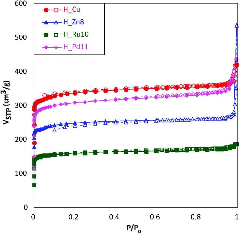 | ||
| Fig. 4 N2 adsorption isotherms at 77 K for H_Cu, H_Zn8, H_Ru10 and H_Pd11. Filled and empty symbols correspond to adsorption and desorption branches, respectively. | ||
The data obtained from the numerical analysis of the isotherms are gathered in Table 3. In concordance to the height of the plateau of the isotherms at intermediate pressures, homometallic H_Cu shows the greatest surface area (SBET), while the inclusion of a second transition metal produces, in all cases, materials with smaller surface areas. This reduction is not only related to the higher atomic weight of the doping metal, as the heaviest of them (Pd) gives greater area values than the lighter ones (Zn and Ru). A possible explanation relies on the influence of the dopant reagent on the crystallinity of the material (considering that a greater number of defects produces a detrimental effect on the porosity). The subtraction of the microporous area from the total surface area leads to external surface area values (area attributable to the outer surface of the MOF particles) ranging from 45 to 284 m2 g−1. In a rough calculation, using the spherical particle approach and corrected crystallographic densities, these external area values imply mean particle sizes of 79, 24, 149, and 67 nm for H_Cu, H_Zn8, H_Ru10 and H_Pd11, respectively. Both the external surface (particle size) and the microporous one (crystal structure of the MOF) are of special relevance in the functionality of the herein studied materials, being beneficial, in general, to achieving high values of both for their use as GDEs.
| Sample | SBET (m2 g−1) | Smicro (m2 g−1) | Sext (m2 g−1) | Vmicro (cm3 g−1) | VT (cm3 g−1) |
|---|---|---|---|---|---|
| a SBET: BET surface area; Smicro: microporous surface area; Sext: external surface area; Vmicro: micropore volume; VT: total pore volume determined at P/Po: 0.993. | |||||
| H_Cu | 1560 | 1474 | 86 | 0.574 | 0.759 |
| H_Zn8 | 1143 | 859 | 284 | 0.333 | 0.968 |
| H_Ru10 | 741 | 696 | 45 | 0.269 | 0.338 |
| H_Pd11 | 1425 | 1325 | 100 | 0.515 | 0.788 |
Cyclic voltammetry characterization
Prior to analysis of all the H_MD samples in the electrochemical cell, a preliminary test by cyclic voltammetry was performed in a CO2-saturated (0.5 M KHCO3) aqueous solution in order to qualitatively assess if the doping exerts any influence on the electrochemical behavior. Fig. 5 gathers the voltammograms yielded by representative MOF-GDEs after 5 scans (remaining samples exhibit a similar trend). The current densities (j) are normalized to the geometric area of the MOF-GDEs.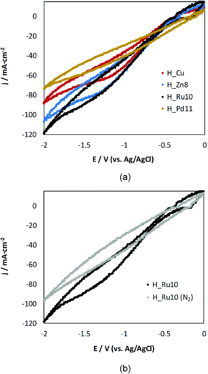 | ||
| Fig. 5 Cyclic-voltammetry responses for (a) H_Zn8, H_Ru10 and H_Pd11 in comparison to H_Cu-based GDEs in a medium saturated with CO2 and, (b) responses for H_Ru10 in the presence and absence of CO2. | ||
All voltammetric curves show a reduction process starting at ca. −1 V versus Ag/AgCl. This reduction peak may be initially assigned to the reduction of CO2. The reduction wave is more pronounced for Zn- and Ru-doped samples than for H_Cu, which indicates their notable activity as a cathode material. It is noteworthy that within the applied voltage, the Ru(III) doped sample appears to be the most promising candidate, while the incorporation of Pd(II) hinders the electroreduction process of CO2 to liquid products. These results can be taken as indicative of the activity, and a deeper insight is presented when describing below the results obtained in the reactor cell.
Continuous electroreduction of CO2
The analysis of the liquid fraction shows that the electrocatalytic reduction of CO2 using the GDEs modified by HKUST-1(Cu,MD) type materials produces methanol (CH3OH) and ethanol (C2H5OH) as major products. It should be noted that neat GDEs (i.e. carbon paper without MOFs) did not generate any measurable liquid product.As representative cases of continuous CO2 reduction capability, Fig. 6 depicts the time-dependence of the total Faraday efficiency (FET) provided by H_Zn8, H_Ru10 and H_Pd11 materials in comparison with H_Cu at fixed current density (j = 20 mA cm−2), gas flow (Qg = 10 mL min−1 cm−2) and electrolyte flow (Qe/A = 2 mL min−1 cm−2). The FE values are calculated considering a 6-electron-pathway for CO2 reduction to CH3OH and a 12-electron-pathway to C2H5OH. It is noteworthy that the outstanding efficiency of the Ru(III) doped sample (FE = 47.2%) is comparable to those relatively stable values provided by Cu2O nanoparticles-based electrodes (FE = 54.8%).18 However, the activity of the Ru(III) doped sample falls abruptly after 60 min of operation to reach a stable plateau close to the 10%. FE values of H_Cu and H_Zn8 show a similar trend, but they start from more moderate values (17–19%) and fall monotonically until stabilizing at values within 12–13%. On the contrary, Pd(II) doped samples show markedly lower FE values (close to the 5%) within the first 2 hours of operation, but fall to a negligible value of 1–2% at longer operation times. Previous works have reported the formation of the less reduced CO as a major product when Pd-based materials are employed as cathode materials, therefore the worsening in the methanol and ethanol yield observed for H_Pd11 is probably due to a change in the product selectivity caused by the dopant.8
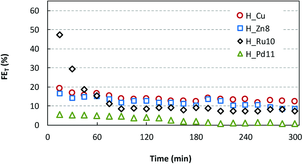 | ||
| Fig. 6 Time-dependence of FE for H_Zn8, H_Ru10 and H_Pd11 materials, in comparison to H_Cu. | ||
To get a deeper insight, the quantitative reduction performances (r and FE) at 90 min of operation time for all samples are summarized in Fig. 7. Further details are provided in the ESI (Table S2†). Regarding the production rates and Faraday efficiencies the maximum values are achieved for the smallest and intermediate Ru and Zn loadings (r = 1.78–2.22 × 10⁻⁵ mol m−2 s−1 and FE of ∼22%), in comparison to those values provided by pristine HKUST-1 (2.66 × 10⁻⁵ mol m−2 s−1 and 12.9%). Further increase of the dopant content produces a lowering of the catalyst performance.
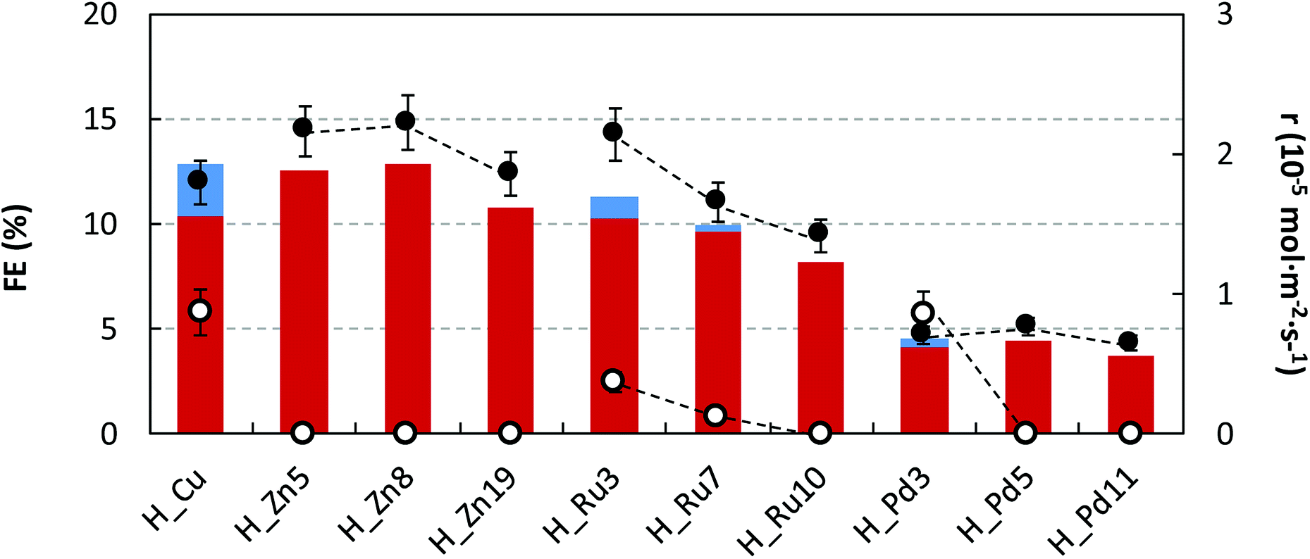 | ||
| Fig. 7 FEs for C2H5OH (in red) and CH3OH (in blue) formation and r for C2H5OH (●) and CH3OH (○) in the electrocatalytic reduction of CO2 at H_Zn, H_Ru and H_Pd in comparison to H_Cu. | ||
Despite ethanol being the major product in the liquid fraction, it seems that the dopant content exerts a certain degree of control on the product selectivity, in such a way that the undoped sample and samples containing the smallest dopant loading exhibit lower selectivity values towards the formation of C2H5OH respective to CH3OH (C2H5OH molar selectivity values estimated from production rates: 67, 55, 85 and 45% for H_Cu, H_Zn5, H_Ru3 and H_Pd3). In all cases, a further increase of the dopant loading promotes an increase of the ethanol selectivity reaching values ranging from 93–100%. This fact might be attributable to the increase of the permanence time caused by the establishment of stronger interactions with the dopant metal, and as a consequence, it would favor a C–C coupling reaction to ethanol. It has been previously hypothesized that C2–C3 products occur through an enol-like surface intermediate, which desorbs to convert to its alcohol, diol and/or keton form.23 The C–C bond formation is one of the most critical factors to be taken into account when designing an efficient electrocatalyst, and further experimental work is needed to fully elucidate CO2 reduction steps to form alcohols using Cu-based GDEs.
Furthermore, to analyze the in-use stability of the MOF-GDEs and its relationship with activity decay observed until the mid-term plateau is achieved, PXRD were measured on fresh electrodes and on those subjected to 45 and 300 min of continuous reaction (Fig. 8a). Whereas fresh electrodes exhibit all the distinctive peaks of the HKUST-1 crystalline phase, their intensity falls progressively as the reaction time increases. In fact, in the most aged electrode (300 min of reaction) only the most intense reflection of the MOF (i.e. 2 2 2) is appreciated. This fact might be related to the material leaching caused by the gas flow at the initial reaction stage. In fact, the comparative SEM images taken on fresh and used electrodes (Fig. 8b) show flat areas from which MOF particles have been detached. Despite this, electrode fatigue is compatible with the aforementioned activity decay, a slow but progressive crystallinity loss of the MOF occurring during operation might also influence this. Note that the full width at half maximum (FWHM) of (2 2 2) reflection varies from 0.12° in the fresh electrode to 0.14° in the one used for 45 min. In any case, it must be pointed out that after 300 min of running, a weak reflection sited at 14.1° emerged, for which a perusal in the powder diffraction files of the Inorganic Crystal Structure Database24,25 matches the most intense reflection of copper(II) formate (ICSD: 109965). It should also be noted that the low sample loading, its dispersion in the GDE and the Nafion matrix, inhibit the observation of further peaks and as a consequence it precludes the univocal identification of the formed crystalline compound. Nonetheless, the formation of copper(II) formate during the reaction would imply a frozen state of a reaction intermediate, which in turn would be the key that favors the formation of more reduced products, such as alcohols. In any case, further research is required to elucidate this plausible mechanism.
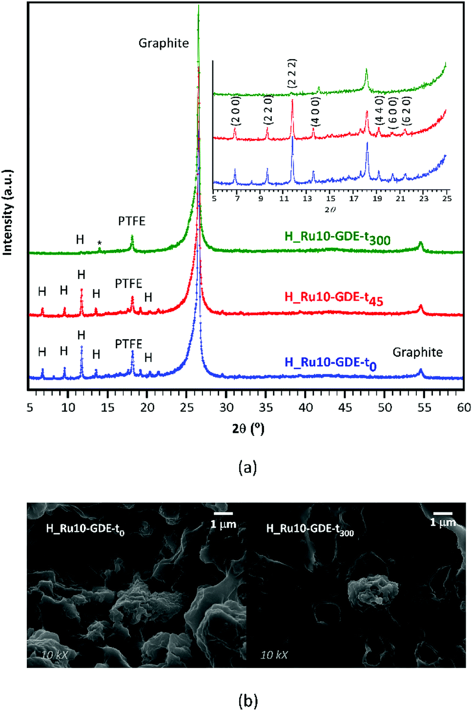 | ||
| Fig. 8 Comparative (a) PXRD patterns and (b) SEM images taken on fresh and used H_Ru10-GDEs (t0, t45 and t300 stand for GDEs subjected to 0, 45 and 300 min). | ||
Conclusions
The solventless synthesis was demonstrated to be a suitable approach and facile route to afford HKUST-1(Cu,MD) type MOFs, in such a way that the dopant (MD) loading can be controlled by its ratio in the reagent mixture. Note that the extremely high reagent concentration implies that the reaction conditions can be a key issue making the controllable doping of MOFs feasible. The products are obtained in high yields and good crystallinity as demonstrated by PXRD analysis and N2 adsorption isotherms. The dopant causes a slight increase of the cell volume attributable to the smaller size of the Cu(II) ion and to the Jahn–Teller contraction implied by the Cu–Ocarboxylate bonds. With regard to the microstructure, it must be emphasized that all the samples consist of sub-micrometric crystals which can be considered as an appealing feature since this fact increases the external surface area and prompts reagent diffusion in catalytic processes.Regarding the electrocatalytic performance of the herein prepared samples, Ru(III) doping has a striking influence on the alcohol yield, reaching relatively high Faraday efficiencies (47.2%) comparable to those provided by nanosized inorganic catalysts. Unfortunately, its activity decays after 60 min of continuous reaction until it reaches a similar performance to that of pristine HKUST-1. Nonetheless, in all cases, the increase of dopant loading promotes a selectivity increase towards ethanol, reaching values ranging from 93 to 100%. This trend might be explained by a favored interplay between the dopant and reaction intermediates, which would lengthen the permanence time, prompting further C–C coupling reactions to ethanol.
Conflicts of interest
There are no conflicts to declare.Acknowledgements
This work has been funded by the Universidad del País Vasco/Euskal Herriko Unibertsitatea (GIU17/50 and PP617/37) and Ministerio de Economía y Competitividad (MAT2016-75883-C2-1-P and CTQ2016-76231-C2-1-R). J. Albo acknowledges the Ramón y Cajal programme (RYC-2015-17080). Technical and human support provided by SGIker (UPV/EHU, MICINN, GV/EJ, ESF) is also acknowledged.Notes and references
- H.-C. Zhou and S. Kitagawa, Chem. Soc. Rev., 2014, 43, 5415 RSC; H.-C. Zhou, J. R. Long and O. M. Yaghi, Chem. Rev., 2012, 112, 673 CrossRef PubMed.
- O. K. Farha, I. Eryazici, N. C. Jeong, B. G. Hauser, C. E. Wilmer, A. A. Sarjeant, R. Q. Snurr, S. T. Nguyen, A. O. Yazaydın and J. T. Hupp, J. Am. Chem. Soc., 2012, 134, 15016 CrossRef PubMed.
- H. Furukawa, K. E. Cordova, M. O'Keeffe and O. M. Yaghi, Science, 2013, 341, 1230444 CrossRef PubMed; B. Valizadeh, T. N. Nguyen and K. C. Stylianou, Polyhedron, 2018, 145, 1 CrossRef.
- D. M. D'Alessandro, B. Smit and J. R. Long, Angew. Chem., Int. Ed., 2010, 49, 6058 CrossRef PubMed; R. M. Cuéllar-Franca and A. Azapagic, J. CO2 Util., 2015, 9, 82 CrossRef.
- W.-J. Ong, L.-L. Tan, Y. H. Ng, S.-T. Yong and S.-P. Chai, Chem. Rev., 2016, 116, 7159 CrossRef PubMed; P. Markewitz, W. Kuckshinrichs, W. Leitner, J. Linssen, P. Zapp, R. Bongartz, A. Schreiber and T. E. Müller, Energy Environ. Sci., 2012, 5, 7281 Search PubMed; S. Gao, Y. Lin, X. Jiao, Y. Sun, Q. Luo, W. Zhang, D. Li, J. Yang and Y. Xie, Nature, 2016, 529, 68 CrossRef PubMed.
- J. Albo, M. Alvarez-Guerra, P. Castaño and A. Irabien, Green Chem., 2015, 17, 2304 RSC.
- J. Qiao, H. Li and J. Zhang, Electrochemical Reduction of Carbon Dioxide. Fundamentals and Technologies, CRC Press, Vancouver, 2016 Search PubMed.
- J. I. W. Feldblyum, M. Liu, D. W. Gidley and A. J. Matzger, J. Am. Chem. Soc., 2011, 133, 18257 CrossRef PubMed; W. Zhang, M. Kauer, O. Halbherr, K. Epp, P. Guo, M. I. Gonzalez, D. J. Xia, C. Wiktor, F. X. L. Xamena, C. Wöll, Y. Wuang, M. Muhler and R. A. Fischer, Chem.–Eur. J., 2016, 22, 14297 CrossRef PubMed; J. Qiao, Y. Liu, F. Hong and J. Zhang, Chem. Soc. Rev., 2014, 43, 631 RSC.
- K. P. Kuhl, E. R. Cave, D. N. Abram and T. F. Jaramillo, Energy Environ. Sci., 2012, 5, 7050 Search PubMed.
- J. Albo, A. Sáez, J. Solla-Gullón, V. Montiel and A. Irabien, Appl. Catal., B, 2015, 176–177, 709 CrossRef.
- J. Albo, G. Beobide, P. Castaño and A. Irabien, J. CO2 Util., 2017, 18, 164 CrossRef.
- M. B. Solomon, T. L. Church and D. M. D'Alessandro, CrystEngComm, 2017, 18, 4049 RSC.
- J. Albo, D. Vallejo, G. Beobide, O. Castillo, P. Castaño and A. Irabien, ChemSusChem, 2017, 10, 1100 CrossRef PubMed.
- M. Lanchas, S. Arcediano, A. T. Aguayo, G. Beobide, O. Castillo, J. Cepeda, D. Vallejo-Sánchez and A. Luque, RSC Adv., 2014, 4, 60409 RSC.
- J. Rodríguez-Carvajal, FULLPROF: A Program for Rietveld Refinement and Pattern Matching Analysis. in Abstracts of the Satellite Meeting on Powder Diffraction of the XV Congress of the IUCr, Toulouse, France; 1990, p. 127 Search PubMed; J. Rodríguez-Carvajal, FULLPROF 2000, version 2.5d, Laboratoire Léon Brillouin (CEA-CNRS), Centre d'Études de Saclay, Gif sur Yvette Cedex, Francia, 2003 Search PubMed.
- C. R. Groom, I. J. Bruno, M. P. Lightfoot and S. C. Ward, Acta Crystallogr., 2016, B72, 171 Search PubMed.
- K. S. Walton and R. Q. Snurr, J. Am. Chem. Soc., 2007, 127, 8552 CrossRef PubMed.
- J. Albo and A. Irabien, J. Catal., 2015, 343, 232 CrossRef.
- W. Zhang, O. Kozachuk, R. Medishetty, A. Schneemann, R. Wagner, K. Khaletskaya, K. Epp and R. A. Fischer, Eur. J. Inorg. Chem., 2015, 3913 CrossRef; O. Kozachuk, K. Yusenko, H. Noei, Y. Wang, S. Walleck, T. Glaserc and R. A. Fischer, Chem. Commun., 2011, 47, 8509 RSC.
- J. G. Santaclara, A. I. Olivos-Suarez, A. Gonzalez-Nelson, D. Osadchii, M. A. Nasalevich, M. A. van der Veen, F. Kapteijn, A. M. Sheveleva, S. L. Veber, M. V. Fedin, A. T. Murray, C. H. Hendon, A. Walsh and J. Gascon, Chem. Mater., 2017, 29, 8963 CrossRef.
- J. Cepeda, S. Pérez-Yáñez, G. Beobide, O. Castillo, E. Goikolea, F. Aguesse, L. Garrido, A. Luque and P. A. Wright, Chem. Mater., 2016, 28, 2519 CrossRef.
- M. Thommes, K. Kaneko, A. V. Neimark, J. P. Olivier, F. Rodriguez-Reinoso, J. Rouquerol and K. S. W. Sing, Pure Appl. Chem., 2015, 87, 1051 CrossRef.
- K. P. Kuhl, E. R. Cave, D. N. Abram and T. F. Jaramillo, Energy Environ. Sci., 2012, 5, 7050 Search PubMed.
- A. Belsky, M. Hellenbrandt, V. L. Karen and P. Luksch, Acta Crystallogr., 2002, B58, 364 Search PubMed.
- K. Okada, M. I. Kay, D. T. Cromer and I. Almodovar, J. Chem. Phys., 1966, 44, 1648 CrossRef.
Footnote |
| † Electronic supplementary information (ESI) available: Synthesis data, powder diffraction patterns, and quantitative data on CO2 electroreduction. See DOI: 10.1039/c8ra02676a |
| This journal is © The Royal Society of Chemistry 2018 |