
 Open Access Article
 This Open Access Article is licensed under a Creative Commons Attribution-Non Commercial 3.0 Unported Licence
Surface modification of CoCr alloys by electrochemical reduction of diazonium salts†
M. A. Mezourab,
Y. Oweisb,
A. A. El-Hadadbc,
S. Algizanib,
F. Tamimi*b and
M. Cerruti*a
aDepartment of Mining and Materials Engineering, McGill University, Montreal, Quebec H3A 2B2, Canada
bFaculty of Dentistry, McGill University, 3640, Strathcona Anatomy and Dentistry Building, Rue University, Montreal, Quebec H3A 0C7, Canada. E-mail: marta.cerruti@mcgill.ca
cPhysics Department, Faculty of Science, Al-Azhar University, Nasr City, Cairo, Egypt
First published on 2nd July 2018
Abstract
Tailoring the surface chemistry of CoCr alloys is of tremendous interest in many biomedical applications. In this work, we show that CoCr can be modified by diazonium electrografting provided the surface is not homogeneously covered with an oxide layer. Cyclic voltammetry (CV) and X-ray photoelectron spectroscopy (XPS) show the electrografting of a poly(aminophenylene) (PAP) layer on CoCr when treated at a reductive potential (CoCr−0.5 V), whereas no PAP film was formed on CoCrOCP and CoCr1 V, treated at open circuit and anodic potentials respectively. Based on XPS results, we attributed the electrografting to the formation of carbide bonds between PAP and the inhomogeneous thin oxide layer of CoCr−0.5 V. We then show an example of application of PAP coatings on CoCr and prove that the presence of a PAP coating on CoCr−0.5 V results in a 5-fold increase of the adherence of poly methyl methacrylate (PMMA) to PAP-coated CoCr compared to uncoated samples; this is of prime significance to improving the long-term stability of dental prostheses. These findings support the importance of reducing the oxide layer for effective functionalization of metal oxides with aryl diazonium salts and suggest a promising surface modification approach for biomedical applications.
1. Introduction
Diazonium-based coatings have been suggested in many applications due to the strong bonds formed between aryl diazonium molecules and the surface of different materials, as well as the possibility of functionalizing the grafted molecules to further tailor surface properties.1–3 For instance, aryldiazonium-based compounds have been successfully employed as coupling agents to bind polymers and macromolecules to a variety of surfaces including carbon-based materials, noble metals and oxides.4–8Aryl diazonium grafting proceeds via a reductive electron transfer to the diazonium salt concerted with the cleavage of dinitrogen and generation of aryl radicals that bind to the electrode surface.9,10 It is generally accepted that aryl diazonium molecules form a covalent carbon–carbon11 or metal–carbon12 bond on carbon-based materials and gold substrates, respectively. This has been extensively studied and proved by spectroscopic studies and DFT calculations.11,12
On the other hand, the evidence for a strong bond between aryl diazonium and oxidized surfaces is much scarcer.13–16 In fact, some studies report that diazonium molecules interact only through weak electrostatic interactions with oxide surfaces, which makes the grafting inefficient.17–19 Other authors, instead, report the formation of covalent bond between aryl diazonium and the metal oxide.9,10,20 For instance, XPS, Raman and time-of-flight secondary ion mass spectrometry (ToF-SIMS) analysis revealed the existence of both M–O–C (metal–oxide–aryl) and M–C (metal–aryl) bonds on Cu,21 Al22 and Mn23 oxides, and only M–O–C on Cr24 and Fe oxides.25 Other authors reported aryl diazonium grafting onto indium tin oxide (ITO),8 fluorine tin oxide (FTO),26 and stainless steel,27 but did not discuss the type of bonds involved.
In this work, we aim at understanding the nature of the bonds formed between aryl diazonium compounds and oxide surfaces using CoCr as a model metal oxide. CoCr alloys are commonly used in a variety of applications, including wind turbines,28 engine components29 as well as orthopedic and orthodontic devices,30,31 thanks to their high biocompatibility, superior wear and corrosion resistance, and good workability and ductility. These properties are directly related to the spontaneous formation of chromium oxide (Cr2O3) and cobalt oxide (CoO) on the CoCr surface. In dentistry, CoCr alloys are bound to acrylic polymers to manufacture dental devices such as removable partial dentures (RPDs)32,33 and resin-bonded partial prostheses.34 However, these devices often fail prematurely due to the poor bond between the metal and the polymeric components.35,36
Several methods have been used to increase the bond strength between polymers and CoCr alloys, including the surface modification of the alloy with silane and phosphate molecules.37–39 However, the low stability of these molecular layers in the pH and temperature conditions experienced in the oral cavity urged us to explore diazonium coating as potential alternative.
Here, we first study how the presence of an oxidation layer on CoCr affects the electrochemical grafting of PAP, and then we show that a thin, cohesive, and covalently bonded PAP film significantly strengthens the adhesion of PMMA to CoCr.
2. Materials and methods
Materials
Cobalt chromium (CoCr alloy super 6) cylinders with a length of 18.71 mm and a diameter of 7.86 mm were obtained from Dental Depot (Fort Lauderdale, USA) and were cut into shorter disks (4.57 mm length). PPD (para-phenylenediamine), sodium nitrite (NaNO2) and ruthenium hexamine trichloride (Ru(NH3)6Cl3) were purchased from Sigma Aldrich (St. Louis, MO). PMMA and MMA were purchased from Great Lakes Orthodontics (Tonawanda, NY). All chemicals were used as received.Methods
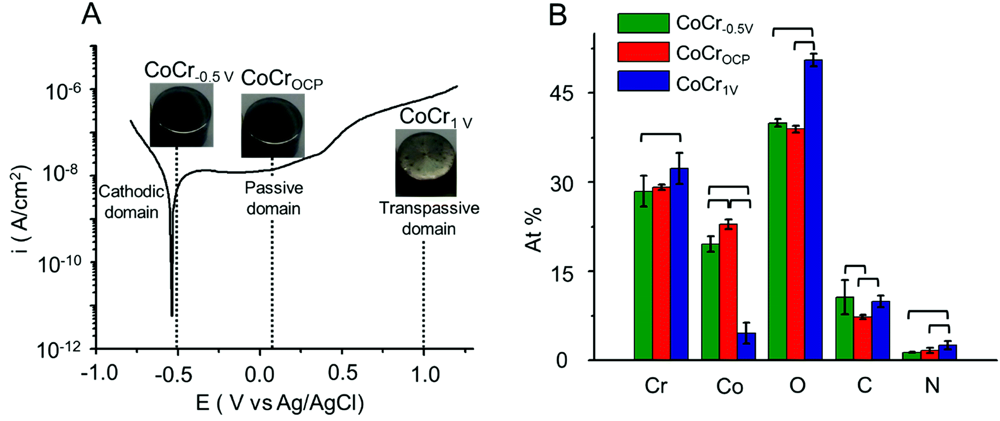 | ||
| Fig. 1 (A) Potentiodynamic curve of CoCr alloy in HCl (0.5 M). The pictures show the visual appearance of CoCr−0.5 V, CoCrOCP and CoCr1 V substrates. These samples were obtained by treatment of CoCr at the potentials of −0.5 V, OCP and 1 V, respectively, selected from the cathodic, passive and transpassive domains. (B) Elemental composition of CoCr−0.5 V, CoCrOCP and CoCr1 V deduced from XPS survey scans. Brackets indicate statistically significant difference between two groups (p < 0.05). | ||
![[thin space (1/6-em)]](https://www.rsc.org/images/entities/char_2009.gif) :1 to make a viscous solution that was poured around the PAP–CoCr disks in the mold and was left to set for 3 h at room temperature. The resulting PMMA–PAP–CoCr specimens were cylindrical in shape and measured 37 mm long and 7.86 mm in diameter. PAP free CoCr discs, referred as PMMA–CoCr, served as control.
:1 to make a viscous solution that was poured around the PAP–CoCr disks in the mold and was left to set for 3 h at room temperature. The resulting PMMA–PAP–CoCr specimens were cylindrical in shape and measured 37 mm long and 7.86 mm in diameter. PAP free CoCr discs, referred as PMMA–CoCr, served as control.3. Results and discussion
To understand the nature of the bond formed between aryl diazonium layer and CoCr alloy, we started by testing different electrochemical pre-treatments aimed at controlling the thickness of the oxide layer present on the CoCr surface.Electrochemical pre-treatment of CoCr surface
A nanometer-thick oxide film grows typically on CoCr upon exposure to oxygen or water at ambient condition.37 This is evidenced by an open circuit potential (OCP) of 0.05 V. The OCP shifts towards more anodic potentials (Fig. S1†) with time indicating an increase in oxide thickness.9Potentiodynamic polarization provides a good qualitative understanding of the oxidation and reduction processes occurring on the CoCr passive film. Fig. 1A represents a typical potentiodynamic curve of CoCr alloy recorded by scanning the potential from −1 V to 1.2 V at 0.01 V s−1 in aqueous HCl solution (0.5 M).
The polarization curve can be divided into three different zones.37 The cathodic zone (E < −0.55 V) is characterized by a negative current mainly dominated by the reduction of water and hydrogen evolution. In the passive zone (−0.3 to 0.6 V), the current remained relatively constant while the thickness of the passivating film grew proportionally with the potential. Finally, in the transpassive zone (E > 0.6 V) a marked increase of current is observed and associated with the dissolution of the oxide layer as well as water oxidation.38
Based on the polarization curve, we selected two potentials in the active and transpassive domains, i.e. −0.5 V and 1 V, respectively, and we applied each potential on the CoCr disks for 15 min (samples labelled CoCr−0.5 V and CoCr1 V, respectively). We used CoCr at OCP, which is located in the passive domain of CoCr, as control (sample labelled CoCrOCP). The visual appearance of the discs after this treatment is shown in the pictures reported in Fig. 1. While CoCr−0.5 V and CoCrOCP showed a smooth and mirror shiny surface similar to CoCr surface before the treatment (Fig. S2†), CoCr1 V showed a rough and brighter appearance, indicative of accelerated surface corrosion.
We assessed the elemental composition of CoCr−0.5 V, CoCr1 V, and CoCrOCP using XPS (Fig. 1B). All samples contained Co, Cr, O and C atoms, in addition to a small amount of N (<2.5%), possibly added during the casting process to improve the mechanical properties of CoCr alloy.39 CoCr−0.5 V and CoCrOCP showed similar amounts of Cr and Co, with just approximately 7% more Cr than Co on average. In contrast, the surface layer on CoCr1 V contained mainly Cr (32 ± 3%) and a lower amount of Co (5 ± 2%). This can be explained by the increasing thickness of the Cr rich oxide layer and the preferential dissolution of Co atoms in the transpassive domain.37 The concentration of O significantly increased going from CoCr−0.5 V to CoCr1 V, indicating a proportional growth of oxide layer at anodic potential. Less C (7 ± 1%) is present on CoCrOCP compared to CoCr−0.5 V (10 ± 1%) and CoCr1 V (11 ± 3%). This might originate from the carbon component of the CoCr alloy and adventitious carbon-based contaminants.
To explore further the chemical environment of surface atoms, we recorded high resolution Cr2p, Co2p, and C1s spectra (Fig. 2 and Table S1†). On all samples, the Cr2p3/2 and Co2p3/2 peaks showed a metallic component at low binding energy and a broader envelope of peaks attributed to multiplet splitting of the oxides and hydroxides peaks.41 In this study, the Cr2p3/2 spectra was fitted with a single peak at approximately 573.8 eV attributed to Cr0 and two oxidized components at approximately 577 eV and 578.6 eV relative to Cr3+ and Cr6+ respectively. The Co2p3/2 envelope was deconvoluted with a metallic Co0 peak at approximately 778 eV, an oxidized component at approximately 779.5 eV corresponding to Co2+, and a satellite peak at approximately 782 eV related to Co2+.41 The carbon peak can be deconvoluted with four components: a low binding energy peak at 283 eV assigned to carbide bonds (C–M),12 possibly due to the inter-dendritic precipitation of carbon during CoCr fabrication,42 a peak at 284.8 eV related to sp3 carbon (C–C), and two peaks at higher binding energies (285 eV and 288 eV) attributed to C–O and C![[double bond, length as m-dash]](https://www.rsc.org/images/entities/char_e001.gif) O bonds respectively.43 The latter three peaks are likely due to adventitious carbon-based contaminants usually found on surfaces exposed to atmosphere.25
O bonds respectively.43 The latter three peaks are likely due to adventitious carbon-based contaminants usually found on surfaces exposed to atmosphere.25
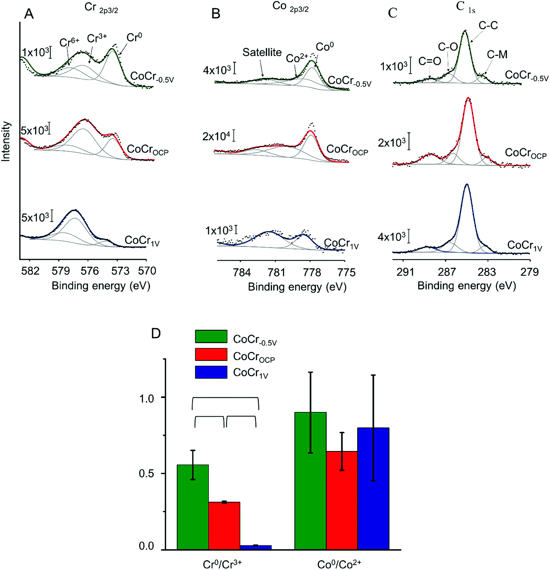 | ||
| Fig. 2 Representative high resolution (A) Cr2p3/2, (B) Co2p3/2 and (C) C1s XPS spectra recorded on CoCr−0.5 V, CoCrOCP, and CoCr1 V. Cr2p1/2 and Co2p1/2 peaks were omitted for clarity. In all panels (A–C), experimental data are shown in black, peak fits in gray and the overall fit in green (CoCr1 V), red (CoCrOCP), or blue (CoCr−0.5 V). (D) Ratio of the areas of the Cr0/Cr3+ and Co0/Co2+ components measured on the high-resolution spectra of Cr and Co for CoCr−0.5 V, CoCrOCP and CoCr1 V. Brackets indicate statistically significant differences between two groups (p < 0.05). | ||
The Cr0/Cr3+ ratio decreased significantly from 0.6 ± 0.1 for CoCr−0.5 V to 0.3 ± 0.05, and to 0.03 ± 0.01 for CoCrOCP and CoCr1 V respectively (Fig. 2D). The high Cr0/Cr3+ ratio observed on CoCr−0.5 V might be explained by the partial elimination of the chromium rich oxide layer that generally forms at ambient conditions (i.e. at OCP). Vice versa, anodic potentials accelerate the growth of the oxide layer, thus decreasing the Cr0/Cr3+ ratio. Differently from Cr, Co showed a higher Co0/Co2+ ratio that does not change significantly with surface treatment. This can be attributed to the lower susceptibility to oxidation of Co relative to Cr.
Overall, these results indicate that an oxide layer is formed on CoCr when treated at anodic potentials. On CoCrOCP the oxide film is composed of a mixture of both Co and Cr, whereas on CoCr1 V, it is mainly dominated by chromium oxides. On the contrary, the oxide layer is partially dissolved on CoCr treated at cathodic potential, i.e. CoCr−0.5 V.
PAP binding as a function of the CoCr surface electrochemical pretreatment
The efficacy of PAP binding on the pretreated CoCr samples can be compared by performing cyclic voltammetry (CV) on these substrates in the presence of PPD and NaNO2 (Fig. 3A).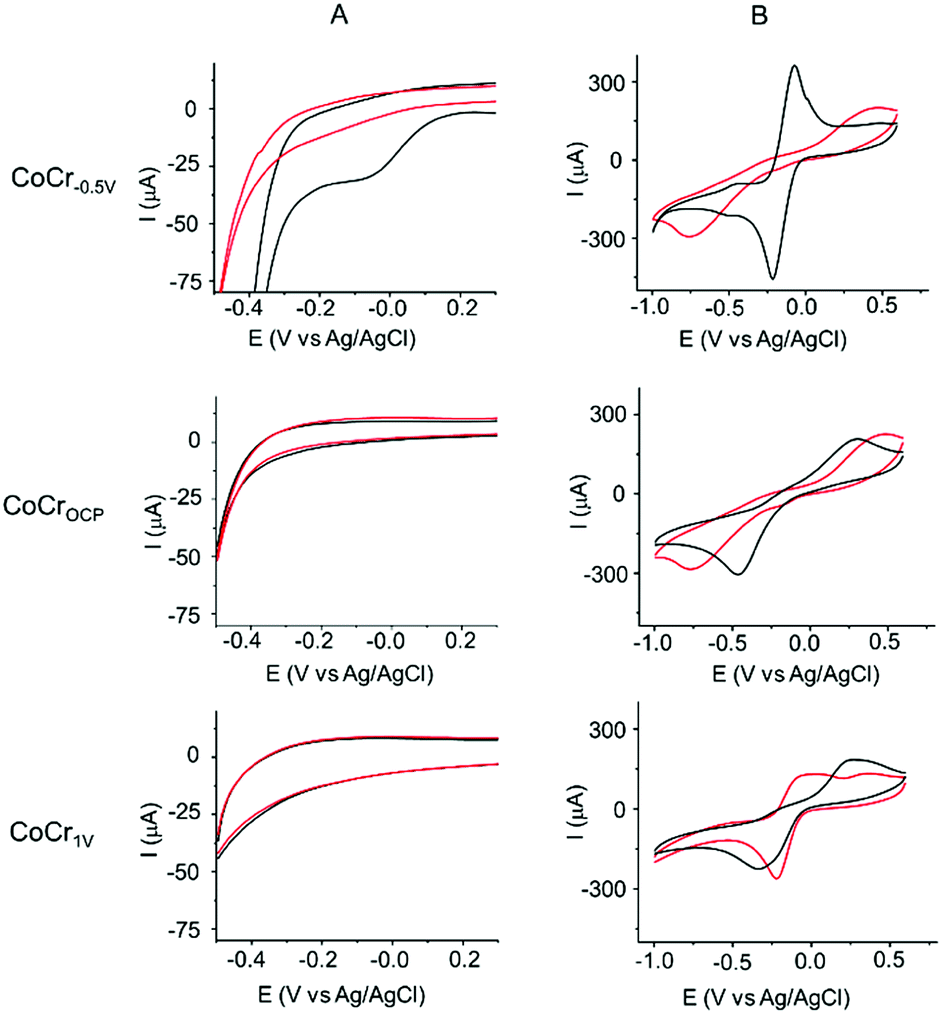 | ||
| Fig. 3 CVs measured on CoCr−0.5 V (first row), CoCrOCP (second row) and CoCr1 V (third row) during and after PAP grafting. (A) CVs performed in de-aerated 0.5 M HCl containing 2 mM of PPD and 1 equivalent of NaNO2. The black and red lines indicate the first and fifth cycles, respectively. (B) CVs performed in aqueous solution of 5 mM Ru(NH3)6Cl3/0.1 M KBr before (black) and after (red) electrochemical binding of PAP. Scan rate was 50 mV s−1. | ||
The first cycle of the CV recorded for PAP binding on CoCr−0.5 V (Fig. 3A, first row) showed a broad irreversible peak at −0.05 ± 0.1 V. In the subsequent CV scans, the current of this reductive peak is drastically diminished and vanishes in the fifth cycle, indicating the passivation of the CoCr−0.5 V electrode by an electrically insulating layer of PAP molecules. This CV behavior is characteristic of a covalent bonding between the in situ generated diazonium radical and the CoCr surface.44–46 No oxidative peak was found in the CV, indicating no polyaniline formation. The control experiments of PAP binding on glassy carbon and gold electrodes showed similar CV behaviour with an irreversible reduction wave at −0.3 V and −0.25 V respectively (Fig. S3†). On the other hand, CoCrOCP and CoCr1 V show a featureless CV suggesting the failure of PAP binding (Fig. 3A, second and third row).
We tested this hypothesis by investigating the blocking properties toward the Ru(NH3)63+/2+ redox couple of the substrates before and after PAP binding (Fig. 3B). The presence of a PAP layer is expected to slow the voltammetric response, causing an increase in the separation between the anodic and cathodic peak potential (ΔEp) and a decrease in the intensity of the cathodic and anodic currents.
Even before electrochemical reduction of PAP (red lines in Fig. 3B), the three surfaces showed different barrier properties toward Ru(NH3)63+/2+. CoCrOCP (Fig. 3B, second row) revealed a large ΔEp (>0.9 V) confirming the presence of a passivating oxide layer on CoCr at OCP. This value is much higher than that measured on CoCr−0.5 V (0.14 V, Fig. 3B, first row) and CoCr1 V (0.6 V, Fig. 3B, third row). The lower barrier towards Ru(NH3)63+/2+ redox reaction shown by CoCr−0.5 V agrees well with the thinner oxide layer observed at cathodic potentials by XPS, while on CoCr1 V the inhomogeneous texture of the transpassive oxide might explain the low resistivity of the surface.47
After PAP binding (black lines in Fig. 3B), no big changes are visible on the CVs measured on CoCrOCP and CoCr1 V (Fig. 3B). This result confirms that PAP binding was inhibited on the oxidized surfaces of CoCrOCP and CoCr1 V. On the contrary, the PAP film grown on CoCr−0.5 V strongly blocks the redox reactions of Ru(NH3)63+/2+, as shown by the marked increase in ΔEp and the significant attenuation of the cathodic and anodic currents (Fig. 3B). The PAP layer formed on CoCr−0.5 V is inhomogeneous (Fig. S5†) and a few nanometer thick, causing an increase in RMS roughness from 1.7 nm before coating to 6 nm after coating (Fig. S6†).
We further assessed PAP formation on the substrates by performing XPS on the PAP coated samples (Fig. 4). As for the uncoated CoCr substrates, the survey scans showed the presence of Cr, Co, O, C and N on all samples (Fig. S4†).
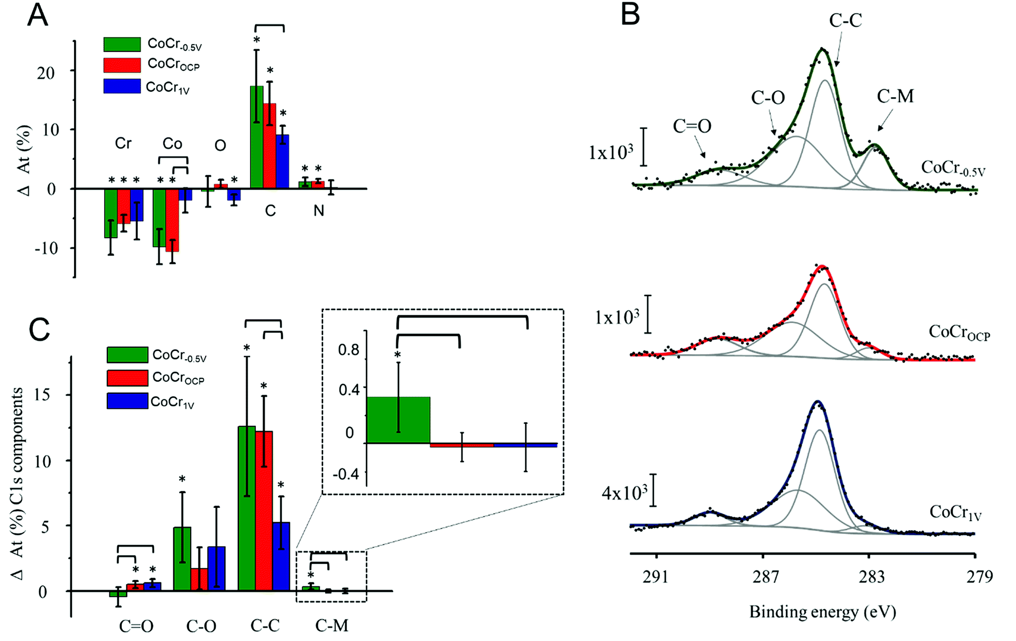 | ||
| Fig. 4 PAP electrografting on CoCr−0.5 V, CoCrOCP, and CoCr1 V analyzed by XPS. (A) Differences in elemental composition measured by XPS survey scans before and after electrografting. (B) Representative high resolution C1s XPS spectra recorded after PAP electrografting. (C) Differences in relative intensities of the components used to deconvolute C1s spectra measured on samples before and after PAP electrografting. Asterisk signs indicate a significant change within the same sample group following PAP treatment (p < 0.05). Brackets indicate statistically significant differences between two groups (p < 0.05). | ||
After PAP binding, we observed a significant increase in C accompanied with a decrease of Co and Cr. The O content remained almost constant and N increased slightly after electrografting on CoCr−0.5 V and CoCrOCP (Fig. 4A). This result indicates the presence of a carbon based organic coating at all CoCr surfaces (regardless of the nature of the oxide layer). The coating might be attributed to PAP film formation, but also to adventitious carbon-based contamination, since electrochemistry did not show evidence of electrografting taking place on CoCrOCP and CoCr1 V (Fig. 3).
To further assess the nature of this organic coating, we analysed the high resolution C1s spectra of the three CoCr substrates (Fig. 4B). The C–C and C–O components increased significantly on all surfaces and are higher on the CoCr−0.5 V than on others; no significant differences among surfaces are detected for the C–O component, and less CO is found on CoCr−0.5 V than on the other surfaces (Fig. 4C). However, again, these components may originate from both PAP layer formation and adventitious contaminants that are hardly avoidable during XPS analysis. The C–M component instead can only originate from the covalent binding between PAP and CoCr. Due to the complex alloy surface composition, we were unable to determine the exact nature of the carbide bond. However, we hypothesize that PAP forms a bond with Cr, since this element is predominantly present on the surface of CoCr−0.5 V (Fig. 2).
The C–M component was previously reported to be a direct proof for the existence of a covalent bond between the aryl group and different substrates (i.e. iron48 and stainless steel49).
After electrografting, this component increased significantly on CoCr−0.5 V compared to CoCrOCP and CoCr1 V. This result indicates that a covalent bond forms only between PAP and the surface of CoCr−0.5 V, which is covered with a thin and inhomogeneous oxide layer. The high resolution N1s spectra of CoCr−0.5 V show a significant increase in the amine peak at 400 eV and decrease of the metal nitride peak at 394 eV after grafting compared to the pristine surface (Fig. S7†). These changes further confirm the presence of a PAP layer on this sample.
This result correlates well with previous studies on aryl diazonium grafting on oxide-free metals such as Au12 and Cu.21 From the XPS and electrochemistry data we can conclude that the electrografting occurs on CoCr when its oxide is reduced.
Efficacy of PAP layer in promoting binding of PMMA to CoCr
We tested the ability of the electrografted PAP layer to improve the adhesion of PMMA to CoCr by simply adding PMMA to the PAP-treated CoCr surfaces and measuring the tensile bond strength at the PMMA–CoCr interface (Fig. 5A). Our hypothesis was that the branched structure of the PAP layer could be exploited to promote PMMA binding through polymeric chain entanglement and hydrogen bonding.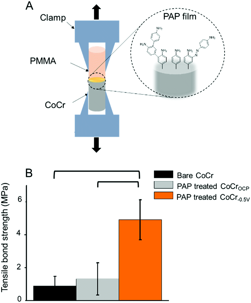 | ||
| Fig. 5 (A) Schematic of the mechanical test designed to measure the interfacial bond strength between different CoCr samples and PMMA. (B) Tensile bond strength between PMMA and bare CoCr (black), PAP-treated CoCrOCP (grey) and PAP-treated CoCr−0.5 V (orange). Brackets indicate statistically significant differences between groups (p < 0.05). | ||
While there were no significant differences between the bond strength measured between PMMA and bare CoCr (0.9 ± 0.6 MPa) vs. PMMA and PAP-treated CoCrOCP (1.4 ± 1.0 MPa), the tensile bond strength measured on PAP-treated CoCr−0.5 V was almost five times higher (5.1 ± 1.2 MPa) (Fig. 5B). This result confirms that the presence of a PAP layer on CoCr−0.5 V significantly increases the bond strength between PMMA and CoCr, likely due to chain entanglement and hydrogen bonds that form between the amine groups of PAP and the carbonyls of PMMA. The lack of significant differences between untreated CoCr and PAP-treated CoCrOCP confirms the failure of PAP coating in the presence of an oxide layer on CoCr.
Several adhesives are reported in the literature to bind PMMA to metals, namely those based on silane and phosphonate molecules.37–39 However, due to differences in test methodology and the fact that the reported coupling agents required some type of surface pretreatment such as sandblasting,44,50 silica coating,51 and alloy priming,52,53 a straightforward comparison between these adhesives and diazonium chemistry is not possible. Instead, the difference between the control and treated groups could be used as an indication of the efficiency of diazonium treatment: in fact, the five fold improvement in tensile bond strength obtained with diazonium is comparable54 than most of the values reported in literature for silane and phosphonates based adhesives, which range between 1.5 and 5 fold.
4. Conclusions
We show that the efficacy of electrografting PAP on CoCr is closely related to the composition of the CoCr surface. The presence of a passivating oxide layer on CoCr at OCP or when electrochemically treated at anodic potentials hinders PAP electrografting. In contrast, reducing the oxide thickness by treating CoCr at cathodic potentials favors PAP electrografting through the formation of metal carbide bonds. The presence of a PAP coating on CoCr−0.5 V results in a 5-fold increase in bond strength between PMMA and CoCr compared to uncoated CoCr samples. Thus, aryl diazonium coating offers a strong and stable alternative to the commonly used silane and phosphonate adhesives: in addition to the comparable or higher increase in strength measured in this work, the bonds formed by diazonium are much more stable in aqueous environments and large pH intervals thanks to the remarkable resistance of C–M bond to hydrolysis.46,55Conflicts of interest
There are no conflicts of interest to declare.Acknowledgements
We acknowledge Natural Sciences and Engineering Research Council (NSERC) of Canada, the Fonds de recherche du Québec – Nature et technologies (FRQNT), the Canada Research Chair foundation (CRC), and the Center of Self-Assembled Chemical Structures. M. A acknowledge the Network for Oral and Bone Health Research (RSBO) and 3DRPDMD for their financial support. Help extended by Dr Bruce Lennox, Dr Sasha Omanovic and Dr Mario Ascencio Pinedo in electrochemical experiments is also acknowledged.Notes and references
- M. Delamar, R. Hitmi, J. Pinson and J. M. Saveant, J. Am. Chem. Soc., 1992, 114, 5883–5884 CrossRef.
- A. Chaussé, M. M. Chehimi, N. Karsi, J. Pinson, F. Podvorica and C. Vautrin-Ul, Chem. Mater., 2002, 14, 392–400 CrossRef.
- C. Cao, Y. Zhang, C. Jiang, M. Qi and G. Liu, ACS Appl. Mater. Interfaces, 2017, 9, 5031–5049 CrossRef PubMed.
- S. Mahouche-Chergui, S. Gam-Derouich, C. Mangeney and M. M. Chehimi, Chem. Soc. Rev., 2011, 40, 4143–4166 RSC.
- H. Mahjoubi, J. M. Kinsella, M. Murshed and M. Cerruti, ACS Appl. Mater. Interfaces, 2014, 6, 9975–9987 CrossRef PubMed.
- O. Alageel, M. N. Abdallah, Z. Y. Luo, J. Del-Rio-Highsmith, M. Cerruti and F. Tamimi, Dent. Mater., 2015, 31, 105–114 CrossRef PubMed.
- X. T. Le, N. D. Doan, T. Dequivre, P. Viel and S. Palacin, ACS Appl. Mater. Interfaces, 2014, 6, 9085–9092 CrossRef PubMed.
- S. Maldonado, T. J. Smith, R. D. Williams, S. Morin, E. Barton and K. J. Stevenson, Langmuir, 2006, 22, 2884–2891 CrossRef PubMed.
- P. Allongue, M. Delamar, B. Desbat, O. Fagebaume, R. Hitmi, J. Pinson and J.-M. Savéant, J. Am. Chem. Soc., 1997, 119, 201–207 CrossRef.
- J. Pinson and F. Podvorica, Chem. Soc. Rev., 2005, 34, 429–439 RSC.
- T. Itoh and R. L. McCreery, J. Am. Chem. Soc., 2002, 124, 10894–10902 CrossRef PubMed.
- L. Laurentius, S. R. Stoyanov, S. Gusarov, A. Kovalenko, R. Du, G. P. Lopinski and M. T. McDermott, ACS Nano, 2011, 5, 4219–4227 CrossRef PubMed.
- J. M. Hicks, Z. Y. Wong, D. J. Scurr, N. Silman, S. K. Jackson, P. M. Mendes, J. W. Aylott and F. J. Rawson, Langmuir, 2017, 33, 4924–4933 CrossRef PubMed.
- V. Rebuttini, E. Fazio, S. Santangelo, F. Neri, G. Caputo, C. Martin, T. Brousse, F. Favier and N. Pinna, Chemical Modification of Graphene Oxide through Diazonium Chemistry and Its Influence on the Structure-Property Relationships of Graphene Oxide-Iron Oxide Nanocomposites, Chem.–Eur. J., 2015, 21, 12465–12474 CrossRef PubMed.
- M. G. Paulik, P. A. Brooksby, A. D. Abell and A. J. Downard, J. Phys. Chem. C, 2007, 111, 7808–7815 CrossRef.
- A. Jacques, S. Devillers, J. Delhalle and Z. Mekhalif, Electrochim. Acta, 2013, 109, 781–789 CrossRef.
- H. Ma, L. Lee, P. A. Brooksby, S. A. Brown, S. J. Fraser, K. C. Gordon, Y. R. Leroux, P. Hapiot and A. J. Downard, J. Phys. Chem. C, 2014, 118, 5820–5826 CrossRef.
- B. Cui, J.-Y. Gu, T. Chen, H.-J. Yan, D. Wang and L.-J. Wan, Langmuir, 2013, 29, 2955–2960 CrossRef PubMed.
- D. R. Jayasundara, R. J. Cullen and P. E. Colavita, Chem. Mater., 2013, 25, 1144–1152 CrossRef.
- D. Belanger and J. Pinson, Chem. Soc. Rev., 2011, 40, 3995–4048 RSC.
- B. L. Hurley and R. L. McCreery, J. Electrochem. Soc., 2004, 151, B252–B259 CrossRef.
- Y. A. Atmane, L. Sicard, A. Lamouri, J. Pinson, M. l. Sicard, C. Masson, S. Nowak, P. Decorse, J.-Y. Piquemal and A. Galtayries, J. Phys. Chem. C, 2013, 117, 26000–26006 CrossRef.
- K. Bell, P. Brooksby, M. Polson and A. Downard, Chem. Commun., 2014, 50, 13687–13690 RSC.
- M. Hinge, M. Ceccato, P. Kingshott, F. Besenbacher, S. U. Pedersen and K. Daasbjerg, New J. Chem., 2009, 33, 2405–2408 RSC.
- K. Brymora, J. Fouineau, A. Eddarir, F. Chau, N. Yaacoub, J.-M. Grenèche, J. Pinson, S. Ammar and F. Calvayrac, J. Nanopart. Res., 2015, 17, 438 CrossRef.
- F. Lamberti, S. Agnoli, L. Brigo, G. Granozzi, M. Giomo and N. Elvassore, ACS Appl. Mater. Interfaces, 2013, 5, 12887–12894 CrossRef PubMed.
- M. Hinge, E. S. Gonçalves, S. U. Pedersen and K. Daasbjerg, Surf. Coat. Technol., 2010, 205, 820–827 CrossRef.
- S. Mercier, F. Iozzelli, M. P. Bacos and P. Josso, in Materials Science Forum, 2004, vol. 461–464, pp. 949–956 Search PubMed.
- Y. S. Wang, S. Narasimhan, J. M. Larson and S. K. Schaefer, J. Mater. Eng. Perform., 1998, 7, 53–65 CrossRef.
- S. H. Teoh, Engineering materials for biomedical applications, World scientific, 2004 Search PubMed.
- L. Shi, D. O. Northwood and Z. Cao, J. Mater. Sci., 1994, 29, 1233–1238 CrossRef.
- Y. S. Al Jabbari, J. Adv. Prosthodont., 2014, 6, 138–145 CrossRef PubMed.
- B. Bergman, A. Hugoson and C. O. Olsson, J. Oral Rehabil., 1995, 22, 595–599 CrossRef PubMed.
- B. E. Pjetursson, W. C. Tan, K. Tan, U. Brägger, M. Zwahlen and N. P. Lang, Clin. Oral. Implants Res., 2008, 19, 131–141 CrossRef PubMed.
- D. G. Castner and B. D. Ratner, Surf. Sci., 2002, 500, 28–60 CrossRef.
- S. Taksali, J. N. Grauer and A. R. Vaccaro, Spine J., 2004, 4, S231–S238 CrossRef PubMed.
- A. Hodgson, S. Kurz, S. Virtanen, V. Fervel, C.-O. Olsson and S. Mischler, Electrochim. Acta, 2004, 49, 2167–2178 CrossRef.
- H. E. Placko, S. A. Brown and J. H. Payer, J. Biomed. Mater. Res., Part A, 1998, 39, 292–299 CrossRef.
- Y. Liao, E. Hoffman, M. Wimmer, A. Fischer, J. Jacobs and L. Marks, Phys. Chem. Chem. Phys., 2013, 15, 746–756 RSC.
- S. Hiromoto, E. Onodera, A. Chiba, K. Asami and T. Hanawa, Biomaterials, 2005, 26, 4912–4923 CrossRef PubMed.
- A. Katerski, A. Mere, V. Kazlauskiene, J. Miskinis, A. Saar, L. Matisen, A. Kikas and M. Krunks, Thin Solid Films, 2008, 516, 7110–7115 CrossRef.
- T. Kilner, R. Pilliar, G. Weatherly and C. Allibert, J. Biomed. Mater. Res., Part A, 1982, 16, 63–79 CrossRef PubMed.
- J. Wilson, J. Walton and G. Beamson, J. Electron Spectrosc. Relat. Phenom., 2001, 121, 183–201 CrossRef.
- T. E. Jacobson, Int. J. Prosthodont., 1989, 2, 163–172 Search PubMed.
- H. Shimizu, K. S. Kurtz, Y. Tachii and Y. Takahashi, J. Dent., 2006, 34, 117–122 CrossRef PubMed.
- M. Rosso, A. Arafat, K. Schroën, M. Giesbers, C. S. Roper, R. Maboudian and H. Zuilhof, Langmuir, 2008, 24, 4007–4012 CrossRef PubMed.
- M. Bojinov, G. Fabricius, T. Laitinen, T. Saario and G. Sundholm, Electrochim. Acta, 1998, 44, 247–261 CrossRef.
- K. Boukerma, M. M. Chehimi, J. Pinson and C. Blomfield, Langmuir, 2003, 19, 6333–6335 CrossRef.
- X. T. Le, G. Zeb, P. Jégou and T. Berthelot, Electrochim. Acta, 2012, 71, 66–72 CrossRef.
- L. Mudford, R. Curtis and J. Walter, J. Dent., 1997, 25, 415–421 CrossRef PubMed.
- K. B. May, J. Fox, M. E. Razzoog and B. R. Lang, J. Prosthet. Dent., 1995, 73, 428–431 CrossRef PubMed.
- C. Ohkubo, I. Watanabe, T. Hosoi and T. Okabe, J. Prosthet. Dent., 2000, 83, 50–57 CrossRef PubMed.
- M. Bulbul and B. Kesim, J. Prosthet. Dent., 2010, 103, 303–308 CrossRef PubMed.
- S.-S. Kim, M.-S. Vang, H.-S. Yang, S.-W. Park and H.-P. Lim, J. Adv. Prosthodont., 2009, 1, 41–46 CrossRef PubMed.
- R. A. Franking, E. C. Landis and R. J. Hamers, Langmuir, 2009, 25, 10676–10684 CrossRef PubMed.
Footnote |
| † Electronic supplementary information (ESI) available. See DOI: 10.1039/c8ra02634c |
| This journal is © The Royal Society of Chemistry 2018 |