 Open Access Article
A facile one-step hydrothermal approach to synthesize hierarchical core–shell NiFe2O4@NiFe2O4 nanosheet arrays on Ni foam with large specific capacitance for supercapacitors†
Xinyang Zhang,
Ziqing Zhang,
Shuanggan Sun,
Yunpeng Wu,
Qiushi Sun and
Xiaoyang Liu *
*
State Key Laboratory of Inorganic Synthesis and Preparative Chemistry, College of Chemistry, Jilin University, Changchun 130012, China. E-mail: liuxy@jlu.edu.cn; Fax: +86-0431-85168316; Tel: +86-0431-85168316
First published on 23rd April 2018
Abstract
In this contribution, NiFe2O4@NiFe2O4 nanosheet arrays (NSAs) with three-dimensional (3D) hierarchical core–shell structures were synthesized by a facile one-step hydrothermal method and they were used as electrode materials for supercapacitors (SCs). The NiFe2O4@NiFe2O4 composite electrode showed a high specific capacitance of 1452.6 F g−1 (5 mA cm−2). It also exhibited a superior cycling stability (93% retention after 3000 cycles). Moreover, an asymmetric supercapacitor (ASC) was constructed utilizing NiFe2O4@NiFe2O4 NSAs and activated carbon (AC) as the positive and negative electrode, respectively. The optimized ASC shows extraordinary performances with a high energy density of 33.6 W h kg−1 at a power density of 367.3 W kg−1 and an excellent cycling stability of 95.3% capacitance retention over 3000 cycles. Therefore, NiFe2O4@NiFe2O4 NSAs have excellent pseudocapacitance properties and are good electrode materials for high energy density.
Introduction
With the continuous development of science and technology, the demand for electric energy is increasing. Therefore, higher electric energy storage is urgently needed. Tremendous efforts have been made to design and develop advanced energy storage devices.1–4 In recent years, supercapacitors (SCs) have been becoming promising and efficient energy storage devices due to their high power density, long cycling life and fast recharge capability.5–7 According to charging and storage mechanisms, SCs can be divided into two classes: electric double-layer capacitors (EDLCs) and pseudocapacitors.8 Pseudocapacitors which utilize the fast reversible redox faradaic reaction of the electrode materials can provide 2–3 times higher specific capacitance than EDLCs.9–12 In this respect, various high-performance electrode materials for pseudocapacitors, including conductive polymers,13–15 transition metal oxides,16–19 hydroxides,20–22 and sulfides23–25 have been investigated in the past few years. As the most promising candidates, ternary transition metal oxides such as ZnFe2O4,26,27 CoFe2O4,28,29 NiFe2O4,30–32 CuFe2O4,33,34 etc., have received considerable attention because of their low cost, natural abundance and environmental compatibility. In particular, ternary nickel ferrite (NiFe2O4) can be utilized as an electrode material for high performance SCs due to it exhibits better electrical conductivity and electrochemical performance than those of binary nickel oxide (NiO) and iron oxide (Fe2O3).35However, due to the low electrical conductivity and relatively small surface areas of transition metal oxides, the kinetics was limited in the redox reaction.36,37 To further improve the specific surface areas of these materials and achieve high specific capacitance, rational design of core–shell nanoarchitectures electrodes on conductive substrates as additive/binder-free electrodes became an attractive strategy.38–41 For instance, You et al. synthesized Co3O4/ZnFe2O4 hollow nanocomposite with a novel starfish-shaped structure by a simple hydrothermal method, of which a high specific capacitance of 326 F g−1 at 1 A g−1 was achieved and a good electrochemical cycling stability (80.7% retention after 1000 cycles) was showed.42 According to Zhang et al., the hierarchical NiCo2O4@MnMoO4 core–shell nanoflowers were synthesized by the hydrothermal method, which showed a good electrochemical performance with specific capacitance of 1118 F g−1 at 1 A g−1, and extraordinary cycling stability (only 12.15% electrochemical performance loss after 5000 cycles).43 More recently, a three dimensional (3D) NiCo2O4@NiCo2O4 core–shell nanoflake arrays were synthesized by Tu et al. using a two-step hydrothermal method, which exhibited a high capacitance of 1.55 F cm−2 at a current density of 2 mA cm−2, and a high electrochemical performance retention rate of 98.6% over 4000 cycles.39
To the best of our knowledge, the core–shell nanomaterials were traditionally fabricated via two steps, by “core” formation on a conductive substrate via electrodeposition or hydrothermal method, and a subsequent “shell” growth step on the surface of the “core”. In this work, we presented a facile one-step synthesis method to fabricate hierarchical NiFe2O4@NiFe2O4 core–shell NSAs on Ni foam as binder-free electrode. It was showed that the nanostructure of NiFe2O4@NiFe2O4 hierarchical core–shell nanosheets can be controlled by simply tuning the reaction time. As expected, the NiFe2O4@NiFe2O4 with the unique core–shell nanostructure manifested high faradaic capacitance as an additive/binder-free electrode for SCs. In addition, we had constructed an asymmetric supercapacitor (ASC) with NiFe2O4@NiFe2O4 NSAs as the positive electrode and AC as the negative electrode. The optimized ASC exhibited a high energy density of 33.6 W h kg−1 at the power density of 367.3 W kg−1, and outstanding cycling stability (95.3% of retention of initial electrochemical performance) after 3000 cycles, indicative of its great potential in high-performance SC applications.
Experimental
Preparation of hierarchical NiFe2O4@NiFe2O4 core–shell NSAs on Ni foam
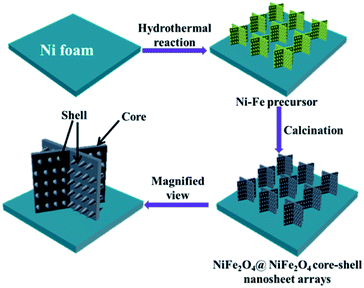
Prior to the synthesis, Ni foam (length × width × thickness = 2 cm × 1 cm × 1.6 mm) were prepared and ultrasonicated cleaned using 3 M HCl solution, deionized water, acetone, and ethanol in sequence to eliminate the possible nickel oxide layer on the surface. NiFe2O4@NiFe2O4 NSAs were synthesized on Ni foam by a facile one-step hydrothermal process. 3 mmol of Ni(NO3)2·6H2O, 2 mmol of Fe3(SO4)2·7H2O, 8 mmol of NH4F and 12 mmol of CO(NH2)2 were dissolved in 100 mL deionized water. The solution was stirred at room temperature and a yellow solution was obtained. The solution was then transferred to a Teflon-lined stainless steel autoclave and the pre-treated Ni foam was immersed into the solution. Subsequently, the autoclave was heated to 100 °C in an airflow electric oven for 2 h, 4 h and 6 h, respectively. After cooling down naturally, the Ni foam was taken out and rinsed with distilled water and alcohol, and it was annealed at 500 °C for 3 h (heating rate of 5 °C min−1). Then the NiFe2O4@NiFe2O4 NSAs could be obtained on the Ni foam surface. The composites obtained with different reaction time of 2 h, 4 h and 6 h were denoted as NFNF-2, NFNF-4 and NFNF-6. Scheme 1 schematically illustrated the fabrication of the NiFe2O4@NiFe2O4 NSAs on the surface Ni foam surface via our proposed one-step hydrothermal method.Materials characterization
The morphology of the NiFe2O4@NiFe2O4 NSAs was characterized by field-emission scanning electron microscopy (SEM, JEOL JSM 6700F) and transmission electron microscopy (TEM, FEI Tecnai G2 F20 S-Twin D573) with acceleration voltage of 200 kV. The energy dispersive X-ray spectroscopy (EDS) spectra were also acquired using a JEOL JSM 6700F microscope. The composition and structure of NiFe2O4@NiFe2O4 NSAs were examined by powder X-ray diffraction (XRD, Rigaku D/Max 2550V/PC, Japan Cu-Kα radiation, λ = 0.15418 nm), and further confirmed by X-ray photoelectron spectroscopy (XPS, ESCALAB 250).Electrochemical characterization
The electrochemical properties of as-prepared electrodes were measured on a CHI 760E electrochemical workstation using a three-electrode system in a 2 M KOH solution. Three-electrode system was consisted of a platinum counter electrode, a saturated calomel electrode (SCE) and the as-prepared hierarchical NiFe2O4@NiFe2O4 NSAs on Ni foam (1 cm × 1 cm), and they acted as the counter electrode, the reference electrode and the working electrode, respectively.Fabrication of NiFe2O4@NiFe2O4//AC ASC
The ASC device was fabricated with NiFe2O4@NiFe2O4 NSAs as the positive electrode, AC as the negative electrode, and the 2 M KOH solution was used as the electrolyte. The specific capacitance, energy densities and power densities of the assembled ASC device were all calculated based on the total mass of both the NiFe2O4@NiFe2O4 and AC electrodes.Results and discussion
Representative XRD and XPS patterns of the hierarchical NiFe2O4@NiFe2O4 NSAs were shown in Fig. 1. To eliminate the influence of the Ni foam, the composites were scratched from the Ni foam before measurement. The XRD patterns of NFNF-2, NFNF-4 and NFNF-6 were shown in Fig. 1a, all the peaks can be readily indexed to the monoclinic NiFe2O4 phase (JCPDS card no. 10-0325), indicating all the three samples were NiFe2O4.44 XPS was carried out to further investigate the surface information of the NiFe2O4@NiFe2O4 NSAs (Fig. 1b–d). As can be seen in the survey scan of as-prepared hierarchical NiFe2O4@NiFe2O4 NSAs (Fig. 1b), the peaks of Ni, Fe and O were observed. Fig. 1c showed that the Ni 2p spectra. The peaks at 873.4 eV and 855.2 eV can be assigned to Ni 2p1/2 and Ni 2p3/2, respectively, which exhibited an separation of 18.2 eV consistent with the previously report.45 The Fe 2p XPS pattern (Fig. 1d) showed two peaks at 725.4 and 711.8 eV, which could be assigned to the binding energy of Fe 2p1/2 and Fe 2p3/2, respectively, suggesting of the existence of Fe3+.46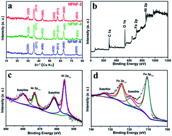 | ||
| Fig. 1 (a) XRD pattern of hierarchical NiFe2O4@NiFe2O4 NSAs scratched from Ni foam; XPS spectra of (b) survey spectrum; (c) Ni 2p; (d) Fe 2p. | ||
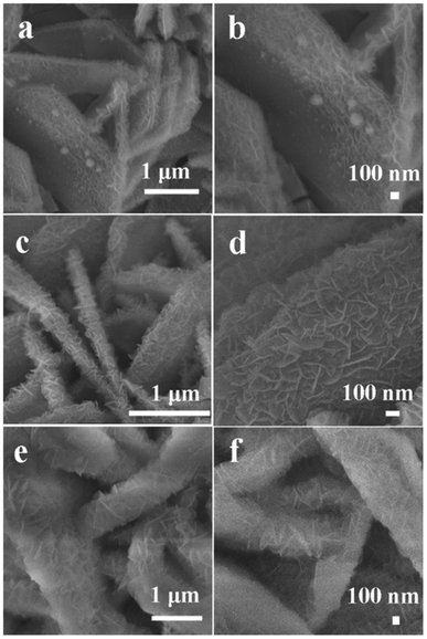
To explore the morphologies of the NiFe2O4@NiFe2O4 NSAs prepared with a different hydrothermal reaction time, the SEM was characterized and the images were collected and shown in Fig. 2. Within a short time (2 h), a number of the tiny NiFe2O4 nanoparticles appeared on the surface of the NiFe2O4 NSAs, acting as the ideal conductive scaffolds. After hydrothermal treatment for 4 h (Fig. 2b), the ultrathin NiFe2O4 nanoflakes were formed and uniformly covered on the surface of the NiFe2O4 nanosheets, developing a unique hierarchical core–shell NiFe2O4@NiFe2O4 NSAs with approximately 1.9 μm wide and 210 nm thick. The hierarchical core–shell NSAs interconnected with each other, and thus a highly porous structure was formed resulting in a large specific surface area, which was beneficial for the electrolyte penetration and ion transportation.47 When the reaction time extended to 6 h (Fig. 2c), the NiFe2O4 nanoflakes gradually occupied the free space between the “core” sheets and almost completely covered the surface of NiFe2O4 nanosheets. In order to obtain the uniform of the core–shell structure of NiFe2O4@NiFe2O4 NSAs on Ni foam, the low magnification SEM was measured and the images were shown in Fig. S1.†
The corresponding TEM images in Fig. 3a–c also revealed the growth process of the NiFe2O4@NiFe2O4 NSAs. As shown in Fig. 3b, the NiFe2O4 core nanosheets were composed of NiFe2O4 nanoflakes of 37 nm in length. Moreover, the representative HRTEM image in Fig. 3d showed that the NFNF-4 NSAs had a set of lattice fringes with interplanar distance of 0.26 nm, well corresponding to the (311) plane of cubic spinel NiFe2O4 (JCPDS card no. 10-0325). To further verify the elemental distribution in the electrode material, the EDS mapping image was obtained and shown in Fig. 3e–h. The results indicated that the Ni, Fe, O elements were uniformly distributed throughout the core–shell nanostructure. Furthermore, the EDS pattern also confirmed the presence of Ni and Fe with an atomic ratio of about 1![[thin space (1/6-em)]](https://www.rsc.org/images/entities/char_2009.gif) :
:![[thin space (1/6-em)]](https://www.rsc.org/images/entities/char_2009.gif) 2 (Fig. S2†).
2 (Fig. S2†).
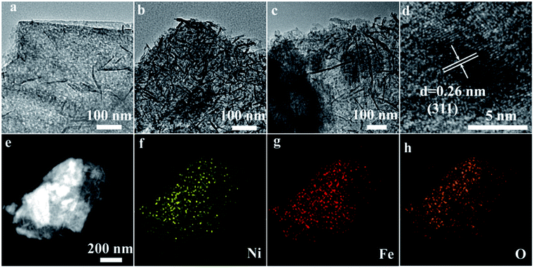 | ||
| Fig. 3 TEM characterization. (a) NFNF-2; (b) NFNF-4; (c) NFNF-6; (d) HRTEM image of NFNF-4 NSAs; (e) EDS of element: (f) Ni, (g) Fe and (h) O. | ||
Electrochemical performance of NiFe2O4@NiFe2O4 NSAs
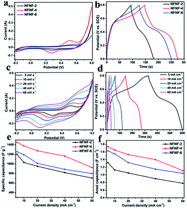
Electrochemical characterizations of NFNF-2, NFNF-4 and NFNF-6 as electrode materials for SCs were carried out by using the three-electrode system in 2 M KOH aqueous solutions (Fig. 4). The cyclic voltammetry (CV) comparison curves of NFNF-2, NFNF-4 and NFNF-6 at the same scanning rate (5 mV s−1) and in the same potential window (−0.2 to 0.8 V) were shown in Fig. 4a. As shown in Fig. 4a, each of the CV curves had a pair of obvious redox peaks, suggesting of the presence of a faradaic reaction. During the charge–discharge process of electrode materials, the mechanism of redox reaction can be represented as the following reaction:31| NiFe2O4 + H2O + OH− ↔ NiOOH + 2FeOOH + e− |
Furthermore, the CV-integral area of the NFNF-4 electrode was higher than those of NFNF-2, NFNF-6 electrodes, demonstrating a significant increase of the areal capacitance. This fact could also be further evidenced by the CD measurements at the same current density (10 mA cm−2) in Fig. 4b. Evidently, the CD curves of NFNF-2, NFNF-4 and NFNF-6 showed a good symmetry, indicating an excellent reversibility. Besides, the CD curve of the NFNF-4 electrode had the longest discharging time, exhibiting the most extraordinary pseudocapacitivity among the three electrodes, which was consistent with the above CV analysis.
Fig. 4c showed the CV curves of the NFNF-4 NSAs electrode for supercapacitor with a same potential range of −0.2 to 0.8 V at various scan rates from 5 to 60 mV s−1. Specifically, a pair of similar redox peaks was observed in all the CV curves, implying that a high-rate faradaic redox reaction happened on the electrode. The NFNF-4 NSAs displayed a pair of redox peaks at 0.520 V and 0.275 V at a slow scan rate of 5 mV s−1. As the scan rate gradually increased, the peak current increased and shape of the CV curves were slightly change, indicating that electrode materials could provide or accept electrons through redox reactions.48 The electrochemical characterizations of the NFNF-4 NSAs was further confirmed by CD measurements at current densities of 5, 10, 20, 40 and 60 mA cm−2 (Fig. 4d). For comparison, the detailed CV and CD measures of the NFNF-2 and NFNF-6 composite electrodes were shown in Fig. S3.†
The mass specific capacitance and areal specific capacitance of the NFNF-2, NFNF-4, and NFNF-6 NSAs electrodes were calculated from the discharge time by the following equations:
| Cm = I × Δt/m × ΔV | (1) |
| Ca = I × Δt/S × ΔV | (2) |
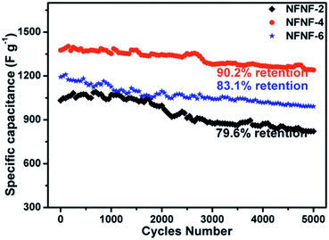
The cycling performance of the NFNF-2, NFNF-4, and NFNF-6 NSAs were also investigated to further evaluate the potential to serve as electrode materials for SCs. As depicted in Fig. 5, cycling stability tests for the NFNF-2, NFNF-4 and NFNF-6 NSAs were performed by measuring the retention rates of their initial capacitances over 5000 cycles at a current density of 10 mA cm−2. After 5000 cycles, the specific capacitance retention rates of the three electrodes were all above 79%. The specific capacitance retention rate of the NFNF-4 electrode (1241.2 F g−1, 90.2% retention) was the highest among the three electrodes, demonstrating the superior electrochemical stability originated from the three-dimensional core–shell structure. Fig. S5 and S6† showed the SEM and Nyquist plots of NiFe2O4@NiFe2O4 core–shell NSAs after 5000 cycling tests. We can observe that the morphology of the core–shell nanosheet arrays retained almost intact, which further demonstrated its high stability.
Electrochemical performance of the NiFe2O4@NiFe2O4//AC ASC
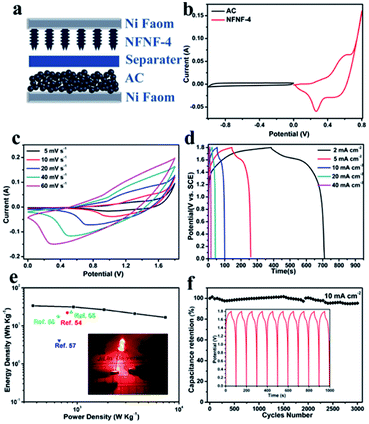
An ASC was assembled utilizing NiFe2O4@NiFe2O4 NSAs as the positive electrode and AC as the negative electrode in 2 M KOH electrolyte, to further confirm the extraordinary electrochemical performance that could be potentially applied in practical applications (Fig. 6a). Fig. 6b showed the CV curves of NFNF-4 and AC electrodes using a three-electrode system at a scan rate of 5 mV s−1. It can be seen that NFNF-4 was measured within a potential window of 0 to 0.8 V, and AC electrode within a potential window of −1.0 to 0 V. The CV curve of AC electrode exhibited a nearly ideal rectangular shape without any redox peaks, demonstrating a typical characteristic of EDLC behavior.53 Based on these results, the total potential window of the assembled ASC could be extended to 0–1.8 V. From the CV curves of the ASC device (Fig. 6c) recorded at different scan rates of 5–60 mV s−1, it was found that the overall capacitance of the NiFe2O4@NiFe2O4//AC ASC device was a result from the combination of both faradaic pseudocapacitance and EDLC-type capacitance. Fig. 6d showed the CD curves of the ASC device at current densities of 2–40 mA cm−2 with the potential window of 0–1.8 V. Ragone plot relative to the corresponding energy density (E) and power density (P) were calculated as follows:| E = C × ΔV2/7.2 | (3) |
| P = 3600 × E/Δt | (4) |
Conclusions
In summary, we have controlled synthesized the hierarchical NiFe2O4@NiFe2O4 core–shell NSAs directly on Ni foam as a additive/binder-free electrode by a facile one-step hydrothermal. The as-prepared NiFe2O4@NiFe2O4 NSAs showed an extraordinary performance with a high specific capacitance for 1377.4 F g−1 (1.65 F cm−2) at 10 mA cm−2, together with an excellent cycling stability of 90.2% retention rate at a high current density of 10 mA cm−2 over 5000 cycles. In addition, the ASC device had been assembled by the NiFe2O4@NiFe2O4 NSAs and AC, which exhibited a high energy density of 33.6 W h kg−1 at a power density of 367.3 W kg−1. The NiFe2O4@NiFe2O4 NSAs was a promising electrode material candidate that could be well applied in the field of renewable energy storage.Conflicts of interest
There are no conflicts to declare.Acknowledgements
This work was supported by the National Sciences Foundation of China (No. 21271082 and 21371068).References
- A. S. Aricò, P. Bruce, B. Scrosati, J. M. Tarascon and W. Van Schalkwijk, Nat. Mater., 2005, 4, 366–377 CrossRef PubMed.
- M. Armand and J. M. Tarascon, Nature, 2008, 451, 652–657 CrossRef CAS PubMed.
- N. S. Choi, Z. Chen, S. A. Freunberger, X. Ji, Y. K. Sun, K. Amine, G. Yushin, L. F. Nazar, J. Cho and P. G. Bruce, Angew. Chem., Int. Ed., 2012, 51, 9994–10024 CrossRef CAS PubMed.
- J. Jiang, Y. Li, J. Liu, X. Huang, C. Yuan and X. W. D. Lou, Adv. Mater., 2012, 24, 5166–5180 CrossRef CAS PubMed.
- T. Brezesinski, J. Wang, S. H. Tolbert and B. Dunn, Nat. Mater., 2010, 9, 146–151 CrossRef CAS PubMed.
- C. Liu, F. Li, L. P. Ma and H. M. Cheng, Adv. Mater., 2010, 22, E28–E62 CrossRef CAS PubMed.
- J. R. Miller and P. Simon, Science, 2008, 321, 651–652 CrossRef CAS PubMed.
- X. Lang, A. Hirata, T. Fujita and M. Chen, Nat. Nanotechnol., 2011, 6, 232–236 CrossRef CAS PubMed.
- X. Li and B. Wei, Nano Energy, 2013, 2, 159–173 CrossRef CAS.
- S. Peng, L. Li, H. B. Wu, S. Madhavi and X. W. D. Lou, Adv. Energy Mater., 2015, 5, 1401172 CrossRef.
- J. Liu, J. Jiang, C. Cheng, H. Li, J. Zhang, H. Gong and H. J. Fan, Adv. Mater., 2011, 23, 2076–2081 CrossRef CAS PubMed.
- G. Wang, L. Zhang and J. Zhang, Chem. Soc. Rev., 2012, 41, 797–828 RSC.
- H. Mi, X. Zhang, X. Ye and S. Yang, J. Power Sources, 2008, 176, 403–409 CrossRef CAS.
- J. Zhang and X. Zhao, J. Phys. Chem. C, 2012, 116, 5420–5426 CAS.
- T. Liu, L. Finn, M. Yu, H. Wang, T. Zhai, X. Lu, Y. Tong and Y. Li, Nano Lett., 2014, 14, 2522–2527 CrossRef CAS PubMed.
- Z. Lu, Z. Chang, J. Liu and X. Sun, Nano Res., 2011, 4, 658–665 CrossRef CAS.
- W. Wei, X. Cui, W. Chen and D. G. Ivey, Chem. Soc. Rev., 2011, 40, 1697–1721 RSC.
- B. Wang, J. S. Chen, Z. Wang, S. Madhavi and X. W. D. Lou, Adv. Energy Mater., 2012, 2, 1188–1192 CrossRef CAS.
- Q. Yang, Z. Lu, X. Sun and J. Liu, Sci. Rep., 2013, 3, 3537 CrossRef PubMed.
- J. Yang, C. Yu, X. Fan and J. Qiu, Adv. Energy Mater., 2014, 4, 1400761 CrossRef.
- D. Yu, Y. Wang, L. Zhang, Z. X. Low, X. Zhang, F. Chen, Y. Feng and H. Wang, Nano Energy, 2014, 10, 153–162 CrossRef CAS.
- Y. Zhu, C. Cao, S. Tao, W. Chu, Z. Wu and Y. Li, Sci. Rep., 2014, 4, 5787 CrossRef CAS PubMed.
- S. Peng, L. Li, C. Li, H. Tan, R. Cai, H. Yu, S. Mhaisalkar, M. Srinivasan, S. Ramakrishna and Q. Yan, Chem. Commun., 2013, 49, 10178–10180 RSC.
- W. Chen, C. Xia and H. N. Alshareef, ACS Nano, 2014, 8, 9531–9541 CrossRef CAS PubMed.
- H. Chen, J. Jiang, L. Zhang, D. Xia, Y. Zhao, D. Guo, T. Qi and H. Wan, J. Power Sources, 2014, 254, 249–257 CrossRef CAS.
- S. S. Raut and B. R. Sankapal, Electrochim. Acta, 2016, 198, 203–211 CrossRef CAS.
- M. M. Vadiyar, S. C. Bhise, S. S. Kolekar, J. Y. Chang, K. S. Ghule and A. V. Ghule, J. Mater. Chem. A, 2016, 4, 3504–3512 CAS.
- L. Liu, H. Zhang, Y. Mu, J. Yang and Y. Wang, ACS Appl. Mater. Interfaces, 2016, 8, 1351–1359 CAS.
- Z. Wang, W. Jia, M. Jiang, C. Chen and Y. Li, Nano Res., 2016, 9, 2026–2033 CrossRef CAS.
- G. Huang, F. Zhang, L. Zhang, X. Du, J. Wang and L. Wang, J. Mater. Chem. A, 2014, 2, 8048–8053 CAS.
- Z. Y. Yu, L. F. Chen and S. H. Yu, J. Mater. Chem. A, 2014, 2, 10889–10894 CAS.
- M. S. Javed, C. Zhang, L. Chen, Y. Xi and C. Hu, J. Mater. Chem. A, 2016, 4, 8851–8859 CAS.
- M. Zhu, D. Meng, C. Wang and G. Diao, ACS Appl. Mater. Interfaces, 2013, 5, 6030–6037 CAS.
- W. Zhang, B. Quan, C. Lee, S. K. Park, X. Li, E. Choi, G. Diao and Y. Piao, ACS Appl. Mater. Interfaces, 2015, 7, 2404–2414 CAS.
- L. Huang, D. Chen, Y. Ding, S. Feng, Z. L. Wang and M. Liu, Nano Lett., 2013, 13, 3135–3139 CrossRef CAS PubMed.
- X. Wang, X. Han, M. Lim, N. Singh, C. L. Gan, M. Jan and P. S. Lee, J. Phys. Chem. C, 2012, 116, 12448–12454 CAS.
- G. Q. Zhang, H. B. Wu, H. E. Hoster, M. B. Chan Park and X. W. D. Lou, Energy Environ. Sci., 2012, 5, 9453–9456 CAS.
- X. Xia, J. Tu, Y. Zhang, X. Wang, C. Gu, X. b. Zhao and H. J. Fan, ACS Nano, 2012, 6, 5531–5538 CrossRef CAS PubMed.
- X. Liu, S. Shi, Q. Xiong, L. Li, Y. Zhang, H. Tang, C. Gu, X. Wang and J. Tu, ACS Appl. Mater. Interfaces, 2013, 5, 8790–8795 CAS.
- K. Xu, R. Zou, W. Li, Q. Liu, X. Liu, L. An and J. Hu, J. Mater. Chem. A, 2014, 2, 10090–10097 CAS.
- Q. Yang, Z. Lu, T. Li, X. Sun and J. Liu, Nano Energy, 2014, 7, 170–178 CrossRef CAS.
- X. W. Hu, S. Liu, B. T. Qu and X. Z. You, ACS Appl. Mater. Interfaces, 2015, 7, 9972–9981 CAS.
- Z. Gu and X. Zhang, J. Mater. Chem. A, 2016, 4, 8249–8254 CAS.
- J. Shao, X. Li, Y. Ding, Z. Wan, H. Liu, J. Yun, Y. Liu, Q. Qu and H. Zheng, Electrochem. Commun., 2014, 40, 9–12 CrossRef CAS.
- J. W. Lee, T. Ahn, D. Soundararajan, J. M. Ko and J. D. Kim, Chem. Commun., 2011, 47, 6305–6307 RSC.
- Q. X. Low and G. W. Ho, Nano Energy, 2014, 5, 28–35 CrossRef CAS.
- D. P. Dubal, G. S. Gund, C. D. Lokhande and R. Holze, ACS Appl. Mater. Interfaces, 2013, 5, 2446–2454 CAS.
- R. Zou, Z. Zhang, M. F. Yuen, J. Hu, C. S. Lee and W. Zhang, Sci. Rep., 2015, 5, 07862 CrossRef PubMed.
- X. Feng, Y. Huang, X. Chen, C. Wei, X. Zhang and M. Chen, J. Mater. Sci., 2018, 53, 2648–2657 CrossRef CAS.
- Y. Zhao, L. Xu, J. Yan, W. Yan, C. Wu, J. Lian, Y. Huang, J. Bao, J. Qiu, L. Xu, Y. Xu, H. Xu and H. Li, J. Alloys Compd., 2017, 726, 608–617 CrossRef CAS.
- P. Bhojane, A. Sharma, M. Pusty, Y. Kumar, S. Sen and P. Shirage, J. Nanosci. Nanotechnol., 2017, 17, 1387–1392 CrossRef CAS.
- B. Senthilkumar, K. V. Sankar, C. Sanjeeviraja and R. K. Selvan, J. Alloys Compd., 2013, 553, 350–357 CrossRef CAS.
- M. D. Stoller, S. Park, Y. Zhu, J. An and R. S. Ruoff, Nano Lett., 2008, 8, 3498–3502 CrossRef CAS PubMed.
- K. Ma, F. Liu, M. Zhang, X. Zhang and J. P. Cheng, Electrochim. Acta, 2017, 225, 425–434 CrossRef CAS.
- N. Kumar, A. Kumar, G.-M. Huang, W.-W. Wu and T. Y. Tseng, Appl. Surf. Sci., 2018, 433, 1100–1112 CrossRef CAS.
- C. Zhao, X. Shao, Y. Zhang and X. Qian, ACS Appl. Mater. Interfaces, 2016, 8, 30133–30142 CAS.
- X. Gao, H. Lv, Z. Li, Q. Xu, H. Liu, Y. Wang and Y. Xia, RSC Adv., 2016, 6, 107278–107285 RSC.
Footnote |
| † Electronic supplementary information (ESI) available. See DOI: 10.1039/c8ra02559b |
| This journal is © The Royal Society of Chemistry 2018 |

