 Open Access Article
Bismuth film electrode and chloranilic acid as a new alternative for simple, fast and sensitive Ge(IV) quantification by adsorptive stripping voltammetry
Malgorzata Grabarczyk * and
Marzena Adamczyk
Faculty of Chemistry, Maria Curie-Sklodowska University, 20-031 Lublin, Poland. E-mail: mgrabarc@poczta.umcs.lublin.pl; Fax: +48 81 5375553; Tel: +48 81 5375588
First published on 23rd April 2018
Abstract
An analytical procedure regarding the voltammetric determination of germanium(IV) by adsorptive stripping voltammetry (AdSV) exploiting the in situ plated bismuth film electrode (BiFE) is described. The use of mercury free electrode as a working electrode is the first time proposed in AdSV germanium determination. The method is based on adsorptive accumulation of the Ge(IV)–chloranilic acid complex at a BiFE by a nonelectrochemical process followed by the cathodic stripping step. Experimental variables, including bismuth and chloranilic acid concentrations, deposition potential and time were carefully optimized. Under optimized conditions the cathodic stripping peak current was directly proportional to the concentration of Ge(IV) in the range from 3 × 10⁻⁹ to 1.5 × 10⁻⁷ mol L−1 with the correlation coefficient 0.997. Because the AdSV technique could be invalidated due to real samples matrix the influence of foreign ions, surface active substances, and humic substances on the Ge(IV) signal was precisely examined. The satisfying minimization of potential matrix interferences was also suggested. Analytical results of natural water samples analysis showed that the proposed procedure of trace germanium(IV) determination is suitable for direct environmental water analysis.
1. Introduction
Germanium has both metallic and nonmetallic properties, similarly to its counterparts in group 14 of the periodic table (carbon, silicon, tin and lead). It has a valence of +2 or +4 but it is usually quadrivalent. Germanium comes in two forms: organic and inorganic, the properties of which differ. The organic form is beneficial for human health, it is believed to have antioxidant properties and anticancer effects. Organic bound germanium is an important element for the immune system and it could capture and discharge the heavy metal toxins such as cadmium and lead.1–4 That is why organic germanium began to be used as an ingredient in health foods and dietary supplements. The germanium-containing supplements became popular in the 1980s and the most common organic germanium compound is known as Ge-132 with the chemical name biscarboxyethyl germanium sesquioxide. However, from the very beginning there was much confusion surrounding the safety of this trace mineral. In 1989 the UK Department of Health warned against germanium supplements holding that they had no nutritional or medical value and that taking them was a health risk, rather than a benefit.5 The inorganic form of germanium is generally considered toxic, as its high intakes can lead to accumulation inside the body and create health hazards. Relatively high doses of germanium dioxide (GeO2) and other inorganic germanium compounds caused severe poisoning including impairments in kidneys, nerves, muscles, and bone marrow.1–4Germanium and its compounds or alloys are widely used in the optical and electronics industries, which presently develop toward smaller and more powerful devices requiring small, high density semiconductor materials. The largest use of germanium is now in the production of infrared sensing and identification systems.6–10 As a result, the world production of germanium products is now increasing and the level of germanium in the environment is beginning to rise. Moreover, germanium is often present in very low levels in environmental waters,11 so it is necessary to perform the determination of trace amounts of germanium in environmental water samples.
The adsorptive stripping voltammetry is a powerful technique for the determination of trace metals in environmental samples. The major advantages of this method are simple and cheap apparatus featuring fast response and high sensitivity, affording adsorptive accumulation of the determined metal as a complex. In the literature several complexing agents for adsorptive accumulation of germanium were employed such as pyrogallol,12 3,4-dihydroxybenzaldehyde (DHB),13 pyrocatechol violet,14 catechol,15–18 gallic acid,19 and recently chloranilic acid.20
A key element of AdSV procedures besides the complexing agent is the kind of working electrode on which the adsorption of metal complexes is performed. Mercury electrodes are almost ideal for this application, so they were used in the overwhelming majority of voltammetric procedures of metals determination. However, the toxicity of mercury electrodes is a serious drawback, so the search for suitable and less toxic electrodes began. A breakthrough in this field was the year 2000 when the bismuth film electrode was introduced by Wang's team.21–23 In the following years numerous analytical applications of this electrode were described in the literature for trace determinations of different metals, such as As(III), Cd(II), Co(II), Cr(VI), Fe(III), Ga(III), In(III), Ni(II), Pb(II), Sb(III), Ti(IV), Tl(I).24–42
In the case of germanium, which is the subject of this work, in almost all AdSV procedures described in the literature mercury electrodes were used12–20 and only in one paper the bismuth film electrode (BiFE) was proposed.21 This may indicate that it is very difficult to replace the toxic mercury electrode by the more environmentally friendly mercury free electrode in compliance with requested analytical parameters. We have described a new adsorptive voltammetric strategy for trace germanium determination using the bismuth film electrode as a working electrode and chloranilic acid as a complexing agent. The main advantage of this procedure of germanium determination in comparison with the earlier described procedure using bismuth film electrode21 is the method of preparation of the working electrode. Zhong et al. recommend that the bismuth film electrode should be organized in ex situ mode, which required an additional step of applying the potential of −1.0 V for 5 min in a separate voltammetric cell and next the transfer of the three-electrode system to a new voltammetric cell containing the analyzed sample where accumulation of germanium for 150 s was performed.21 In our procedure the in situ bismuth film electrode was used, so the whole measurement including preparation of BiFE, germanium accumulation, and stripping was performed in one cell and proceeded in less than one minute.
Another advantage of our procedure is its insensitivity to relatively high concentrations of organic compounds, such as surface active compounds, humic compounds and natural organic matter, which disturb the voltammetric signal of germanium in other voltammetric procedures using both the bismuth film electrode21 and the mercury electrode.19
2. Experimental
2.1. Apparatus
The measurements were performed using a μAutolab PGSTAT 10 analyzer (Utrecht, The Netherlands). The classical three-electrode voltammetric quartz cell consisted of a glassy carbon electrode give supplier on which bismuth film was in situ plated, a Pt wire as an auxiliary electrode and an Ag/AgCl reference electrode (saturated NaCl). Before each series of measurements the glassy carbon electrode of 1 mm diameter was polished daily on 2000 grit sandpaper whereupon using 0.3 μm alumina slurry on the Buehler polishing pad.2.2. Reagents
A stock solution of 1 g L−1 Ge(IV) was obtained from Merck (Darmstadt, Germany), the working solutions of Ge(IV) of lower concentrations were prepared by dilution of the stock solution by 5 × 10⁻³ mol L−1 of HNO3 as required. A standard solution of 1 g L−1 Bi(III), chloranilic acid, Triton X-100, sodium dodecyl sulfate (SDS), and cetyltrimethylammonium bromide (CTAB) were purchased from Fluka (Buchs, Switzerland). A working solution of 1 × 10⁻² mol L−1 of chloranilic acid was prepared by dissolving 0.0209 g of the reagent in water in a 10 mL volumetric flask. Suprapur CH3COOH and NaOH were obtained from Merck. Humic acid sodium salt (HA) was obtained from Aldrich. Natural organic matter (NOM) and river fulvic acid (FA) were obtained from the Suwannee River and purchased from the International Humic Substances Society. Biosurfactant (rhamnolipids) and Amberlite XAD-7 resin were obtained from Sigma (St. Luis, MO, USA). Amberlite XAD-7 was washed four times with triply distilled water before use and dried at the temperature of 50 °C.2.3. Sample preparation
In order to minimize organic matrix interferences the samples containing surfactants or humic substances were mixed with the Amberlite XAD-7 resin before the voltammetric measurement. For this purpose a sample solution, 1 mL of 1 mol L−1 CH3COOH and an adequate volume of triply distilled water, so that the final volume of the solution was 10 mL, were added to a glass vial and next 0.5 g of XAD-7 resin was inserted. Then, the resulting solutions was stirred using a magnetic stirring bar for 5 min. During that time the organic substances were adsorbed on the resin, while germanium(IV) ions remained in solution. Finally, after sedimentation of the resin 5 mL of the solution was pipetted into the electrochemical cell, and a voltammetric measurement was performed.2.4. Measurement procedure
All voltammetric measurements were carried out in 0.1 mol L−1 acetic acid solution containing 2.5 × 10⁻⁵ mol L−1 Bi(III) to generate bismuth film and 5 × 10⁻⁴ mol L−1 chloranilic acid as a complexing agent. The experiments were carried out in non-deaerated solutions at room temperature. The voltammetric procedure consisted of the following main steps:• −1.0 V for 20 s (bismuth film was plated by the reduction of Bi(III) to bismuth metallic state);
• −0.35 V for 30 s (accumulation of Ge(IV)–chloranilic acid complexes on BiFE);
• the potential was scanned from −0.35 V to −0.8 V (differential pulse stripping voltammogram was recorded corresponding to the reduction of the accumulated complex; the germanium peak appeared at about −0.54 V).
A magnetic stirrer was used during the first two steps. After each measurement the electrochemical cleaning was carried out in the following way: −1.4 V for 15 s and +0.3 V for 15 s under stirring. During the first step the products from the measurement were reduced to the metallic state and then they and bismuth film were stripped from the glassy carbon electrode.
3. Optimization of analytical conditions
3.1. Supporting electrolyte
The influence of electrolyte composition on the peak current of germanium using the in situ plated BiFE was investigated separately. The previous articles about the application of such a working electrode show that the acetic acid solution should be used. Among electrolytes that were investigated in this work, such as H2SO4, HNO3, HClO4, HCl, CH3COOH, the best results (higher sensitivity) were obtained in acetic acid solution. So the effect of CH3COOH concentration was studied in the range from 0.05 to 0.2 mol L−1. The experiments showed that in the whole concentration range the analytical signal of germanium was the same. Consequently, as the supporting electrolyte 0.1 mol L−1 CH3COOH was used for further measurements.3.2. Bismuth concentration
In the case of an in situ plated bismuth film electrode Bi(III) should be added directly to the sample solution in the presence of acetic acid supporting electrolyte to avoid its hydrolysis. So the influence of Bi(III) concentration was studied for the synthetic solution containing 0.1 mol L−1 CH3COOH, 5 × 10⁻⁴ mol L−1 chloranilic acid, and 5 × 10⁻⁸ mol L−1 Ge(IV) while the concentration of Bi(III) was changed from 0 to 1 × 10⁻⁴ mol L−1. The obtained results are presented in Fig. 1. It was observed that the presence of the bismuth film is necessary to obtain the analytical signal for germanium. At Bi(III) concentration ranging from 2.5 × 10⁻⁶ mol L−1 to 2.5 × 10⁻⁵ mol L−1 the peak current of germanium increased and finally reached a maximum and next with the increase of bismuth concentration the germanium signal progressively decreased. On the basis of these results the Bi(III) concentration of 2.5 × 10⁻⁵ mol L−1 was chosen as the optimal one.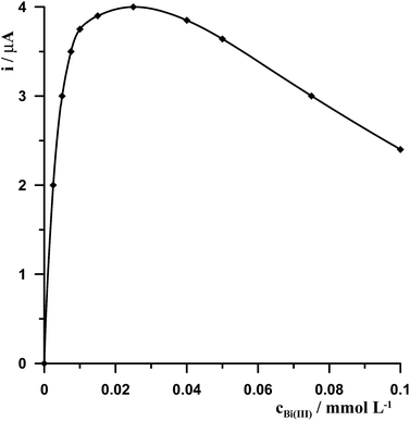 | ||
| Fig. 1 The influence of Bi(III) concentration on 5 × 10⁻⁸ mol L−1 Ge(IV) voltammetric signal. Concentrations of 5 × 10⁻⁴ mol L−1 chloranilic acid and 0.1 mol L−1 CH3COOH. | ||
3.3. Chloranilic acid concentration
The chloranilic acid concentration had a considerable effect on the linear range and sensitivity of the method, so it was studied for Ge(IV) at the levels of 1 × 10⁻⁸ mol L−1 and 5 × 10⁻⁸ mol L−1, while other standard measuring conditions remained constant (0.1 mol L−1 CH3COOH, 2.5 × 10⁻⁵ mol L−1 Bi(III)). Chloranilic acid concentration was changed from 0 to 2 × 10⁻³ mol L−1. The results show that in the absence or presence of low concentrations of chloranilic acid below 1 × 10⁻⁴ mol L−1 the germanium signal is not observed. Then with the increase of complexing agent concentrations to 2 × 10⁻³ mol L−1 the peak current increases, but at higher concentrations it increases very slightly. Moreover, at chloranilic acid concentration equal to 2 × 10⁻³ mol L−1 the linear range of the bismuth calibration curve is below one order of magnitude. So the concentration of the complexing agent equal to 5 × 10⁻⁴ mol L−1 was selected as a compromise between sensitivity and the linear range of the calibration curve.3.4. Potential and time of bismuth film formation and Ge(IV)–chloranilic acid accumulation
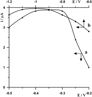
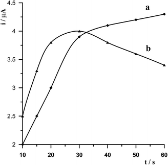
The effect of the electrode potential on bismuth film formation and Ge(IV)–chloranilic acid accumulation was studied for a solution containing 5 × 10⁻⁸ mol L−1 Ge(IV). On the basis of the performed measurements it was found that the best signal of germanium was obtained by applying a combination of two successive steps −1.0 V for 20 s followed by −0.35 V for 30 s. The optimization of these parameters was carried out by changing the second potential while the first potential was fixed and then the second potential was fixed while the first potential was modified. So at first the potential −1.0 V and time 20 s were selected for bismuth film formation while the potential of Ge(IV)–chloranilic acid accumulation was changed in the range from −0.5 V to −0.2 V and accumulation time 30 s. The obtained results are presented in Fig. 2a. It was found that for the potential of accumulation in the range from −0.4 V to −0.3 V the peak of germanium was the same, whereas for less negative and more negative potentials the peak height decreased. Therefore, the potential of −0.35 V for Ge(IV)–chloranilic acid accumulation was selected as the optimum one. The effect of Ge(IV)–chloranilic acid accumulation time was tested from 10 s to 60 s using the accumulation potential of −0.35 V. We have observed that the peak current of germanium increased as the accumulation time increased, however for a time longer than 30 s the growth of bismuth peak current was slight (Fig. 3a).Then the potential of Ge(IV)–chloranilic acid accumulation was fixed and was equal to −0.35 V and 30 s accumulation time, while the potential of bismuth film formation was changed in the range from −1.2 V to −0.6 V at 20 s. The obtained results are presented in Fig. 2b. To sum up the obtained results, in the range from −1.1 V to −0.9 V the peak of germanium remained the same, so the potential of −1.0 V for bismuth film formation was chosen as an optimum value. The effect of bismuth film formation time was tested by changing from 10 s to 60 s using the potential of −1.0 V. The peak current of germanium increased as the film formation time increased to 30 s and next progressively decreased (Fig. 3b).
3.5. Analytical parameters
The calibration graph for the determination of germanium was obtained for the solution under the optimized conditions, 0.1 mol L−1 CH3COOH, 2.5 × 10⁻³ mol L−1 Bi(III), and 5 × 10⁻⁴ mol L−1 chloranilic acid. Under such conditions the calibration graph for Ge(IV) was linear in the range from 3 × 10⁻⁹ to 1.5 × 10⁻⁷ mol L−1 and obeyed the equation y = 73.12x + 0.15, where y and x are the peak current (μampere) and Ge(IV) the concentration (μmol per liter), respectively. The linear correlation coefficient was r = 0.997. The precision expressed as the relative standard deviation (R.S.D.) was 3.3% for five successive measurements of the same sample 5 × 10⁻⁹ mol L−1 Ge(IV). The detection limit estimated from three times the standard deviation at low Ge(IV) concentration was about 1.2 × 10⁻⁹ mol L−1.4. Interferences
4.1. Effect of foreign ions
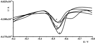
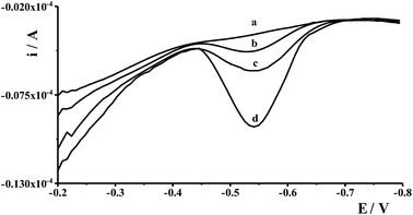
Interferences in the adsorptive voltammetric procedure may be caused by foreign ions as a result of their competitive adsorption or their complexes on the working electrode surface. The effects of co-existing ions were tested using a fixed concentration of Ge(IV) equal to 1 × 10⁻⁷ mol L−1 and different concentrations of several foreign ions. An ion was considered to interfere when its presence produced a variation in the germanium peak current > 5%. The results showed that up to a 100-fold excess of Al(III), Ca(II), Cr(III), Cr(VI), Cu(II), Ga(III), In(III), Mg(II), Mn(II), Pb(II), V(V), Zn(II), and 50-fold excess of Co(II), Cd(II), Ni(II), Fe(III), Sb(III) did not have a significant effect on the Ge(IV) peak. The most interfering ions were Hg(II), Mo(VI), Se(IV), and Ti(IV) whose 50-fold excess caused a decrease of the germanium peak to 40%, 70%, 75%, and 40% of its original value, respectively. The voltammograms recorded for solutions containing 1 × 10⁻⁷ mol L−1 Ge(IV) and 5 × 10⁻⁶ mol L−1 interfering ions: Hg(II), Mo(VI), Se(IV) and Ti(IV) are presented in Fig. 4.4.2. Effect of surface active and humic substances
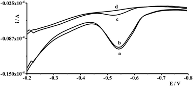
One of the drawbacks of adsorptive voltammetric methods is the sensitivity to organic matter, such as surface active and humic substances which are present in real samples. The interferences are caused mainly by the adsorption of those substances on the working electrode and consequently its blockade, which in turn results in a decrease or total decay of the analytical signal of the determined element. Organic matter interferences also concern adsorptive voltammetric determination of germanium using as a working electrode the mercury electrodes19,20 as well as BiFE as we have proved in this work. The measurements were performed by testing the influence of different kinds of surfactants on the germanium signal, such as Triton X-100 (non-ionic), cetyltrimethylammonium bromide (CTAB-cationic), sodium dodecylsulfate (SDS-anionic), and rhamnolipid (biosurfactant), humic acids (HA), fulvic acids (FA), and natural organic matrix (NOM). The experiments were performed by measuring the peak height of the germanium signal using the solutions containing a constant concentration of Ge(IV) equal to 5 × 10⁻⁸ mol L−1 and different concentrations of the organic substances. It was concluded that the voltammetric signal of germanium is very sensitive to the presence of both surface active substances and humic substances and that their concentrations in the range of 1–2 mg L−1 cause total decay of the germanium peak current. So with a view to eliminate these interferences the preliminary mixing of the analyzed sample with Amberlite XAD-7 resin as described in chapter Sample preparation was introduced. During this step the organic substances have a tendency to adsorb on the resin while the monitored germanium ions remain in solution. Applying such a procedure the organic substances do not affect the germanium signal in the concentration range of 5–20 mg L−1. Detailed results of the influence of different kinds of surface active substances and humic substances using a standard procedure and the procedure with mixing with the resin are presented in Table 1. In Fig. 5 the examples of voltammograms recorded in the presence of different concentrations of Triton X-1000 using the procedure with or without mixing with resin are shown.| Kind of organic substance | Standard procedure | Procedure with mixing with resin | ||
|---|---|---|---|---|
| Concentration of organic substance [mg L−1] | Decrease of Ge(IV) signal in % | Concentration of organic substance [mg L−1] | Decrease of Ge(IV) signal in % | |
| Triton X-100 | 0.5 | 75 | 20 | 0 |
| 1.0 | 95 | 40 | 10 | |
| 1.5 | No signal | 60 | 15 | |
| CTAB | 0.5 | 50 | 20 | 0 |
| 1.0 | 80 | 40 | 15 | |
| 2.0 | No signal | 60 | 25 | |
| SDS | 0.5 | 50 | 20 | 0 |
| 1.0 | 85 | 40 | 10 | |
| 2.0 | No signal | 60 | 20 | |
| Rhamnolipid | 0.5 | 40 | 5 | 0 |
| 1 | 90 | 10 | 20 | |
| 1.5 | No signal | 20 | 30 | |
| 40 | 50 | |||
| 60 | 65 | |||
| HA | 0.5 | 30 | 5 | 0 |
| 1.0 | 95 | 10 | 10 | |
| 1.5 | No signal | 20 | 40 | |
| 40 | 85 | |||
| FA | 0.5 | 80 | 5 | 0 |
| 1.0 | No signal | 10 | 5 | |
| 20 | 30 | |||
| 40 | 75 | |||
| NOM | 0.5 | 25 | 5 | 0 |
| 1.0 | 90 | 10 | 10 | |
| 1.5 | No signal | 20 | 40 | |
| 40 | 75 | |||
5. Application of the proposed procedures
In order to validate the proposed procedure, recovery tests were carried out by taking four fresh natural water samples collected from different places and by adding known quantities of Ge(IV) standard in the sample. The samples were collected from eastern areas of Poland, river waters (the Bystrzyca and the Krezniczanka rivers), stagnant water (Lake Zemborzyce), tap water and were submitted to analysis without any pretreatment. The voltammograms obtained in the course of Ge(IV) determination for water samples did not exhibit any signals, so the analyzed samples were spiked with Ge(IV) at different concentration levels and analyzed using the standard addition method based on three runs of measurements. The results of the recovered values were found to be within ±4.7%, which proved that the proposed procedure was adequately satisfactory for the analysis of natural water samples. The voltammograms obtained during the analysis of Lake Zemborzyce stagnant water are presented in Fig. 6.6. Conclusions
The bismuth film electrode and chloranilic acid as a new alternative for the simple, fast and sensitive Ge(IV) quantification by adsorptive stripping voltammetry were successfully proposed. The main advantage of the procedure is that the toxic mercury electrode was replaced by a more environmentally friendly in situ plated bismuth film electrode as a working electrode. The application of an in situ formed film electrode shortens the total time of measurements. Another advantage is the possibility to carry out the measurements in undeaerated solutions. Moreover, the proposed adsorptive stripping voltammetric method offers the advantages of accuracy as well as simplicity of reagents and apparatus. It should also be mentioned that the described procedure is insensitive to high concentrations of surface active substances and humic substances. To prove its practical applicability, the procedure was successfully tested for the detection of germanium in different non-pretreated and non-deaerated real water samples.Conflicts of interest
There are no conflicts to declare.References
- L. S. Keith, O. M. Faroon, N. Maples-Reynolds and B. E. Fowler, Germanium, Handbook on the Toxicology of Metals, ed. Gunnar Nordberg, B. Fowler and M. Nordberg, Elsevier, 4th edn, 2014, pp. 799–816 Search PubMed.
- M. Banasik, Germanium, in Hamilton and Hardy's Industrial Toxicology, ed. Raymond D. Harbison, M. M. Bourgeois and G. T. Johnson, Wiley, 6th edn, 2015, pp. 119–122 Search PubMed.
- Y. Katsuhiko, Germanium, Toxicity, in Encyclopedia of Metalloproteins, ed. R. H. Kretsinger, V. N. Uversky and E. A. Permyakov, Springer, 2013. pp. 842–846 Search PubMed.
- A. F. Koca, I. Koca and B. Tekguler, Acta Hortic., 2016, 1143, 297–302 CrossRef.
- J. Emsley, Nature's Building Blocks: An A-Z Guide to the Elements, Oxford University Press, New York, 2011, pp. 197–201 Search PubMed.
- E. Rosenberg, Rev. Environ. Sci. Bio/Technol., 2009, 8, 29–57 CrossRef CAS.
- R. R. Moskalyk, Miner. Eng., 2004, 17, 393–402 CrossRef CAS.
- B. Depuydt, A. Theuwis and I. Romandi, Mater. Sci. Semicond. Process., 2006, 9, 437–443 CrossRef CAS.
- E. E. Haller, Mater. Sci. Semicond. Process., 2006, 9, 408–422 CrossRef CAS.
- N. S. Medvedev, A. V. Shaverina, A. R. Tsygankova and A. I. Saprykin, Talanta, 2016, 155, 358–362 CrossRef CAS PubMed.
- S. Jianbo, T. Zhiyong, T. Chunhua, Ch. Quan and J. Zexiang, Talanta, 2002, 56, 711–716 CrossRef PubMed.
- Ch. Q. Sun, Q. Gao and L. L. Liu, Talanta, 1995, 42, 881–884 CrossRef CAS PubMed.
- Ch. Q. Sun, Q. Gao, J. Xi and H. Xu, Anal. Chim. Acta, 1995, 309, 89–93 CrossRef CAS.
- A. M. Bond, S. Kratsis and O. M. G. Newman, Electroanalysis, 1998, 10, 387–392 CrossRef CAS.
- J. L. Muniz Alvarez, J. A. Garcia Calzon and J. M. Lopez Fonseca, Electroanalysis, 1999, 11, 656–659 CrossRef CAS.
- J. L. Muniz Alvarez, J. A. Garcia Calzon and J. M. Lopez Fonseca, Talanta, 2001, 53, 721–731 CrossRef CAS PubMed.
- S. Y. Ly, S. S. Song, S. K. Kim, Y. S. Jung and Ch. H. Lee, Food Chem., 2006, 95, 337–343 CrossRef CAS.
- R. Piech, J. Appl. Electrochem., 2011, 41, 207–214 CrossRef CAS.
- Y. H. Li, X. H. Chen, M. H. Huang and F. Q. Zhou, Electroanalysis, 2007, 19, 704–708 CrossRef CAS.
- M. Grabarczyk, J. Electrochem. Soc., 2017, 164, H872–H876 CrossRef CAS.
- S. Zhong, J. Su, L. Chen, J. Tong, W. Jia, X. Li and H. Zou, Int. J. Electrochem. Sci., 2013, 2013, 735019 Search PubMed , 7 pages.
- J. Wang, J. Lu, S. B. Hocevar and P. A. M. Farias, Anal. Chem., 2000, 72, 3218–3222 CrossRef CAS PubMed.
- J. Wang, J. Lu, U. A. Kirgoz, S. B. Hocevar and B. Ogorevc, Anal. Chim. Acta, 2001, 434, 29–34 CrossRef CAS.
- L. Jiajie and Y. Nagaosa, Anal. Chim. Acta, 2007, 593, 1–6 CrossRef CAS PubMed.
- A. Królicka, R. Pauliukaite, I. Svancara, R. Metelka, A. Bobrowski, E. Norkus, K. Kalcher and K. Vytras, Electrochem. Commun., 2002, 4, 193–196 CrossRef.
- N. Lezi, A. Economou, P. A. Dimovasilis, P. N. Trikalitis and M. I. Prodromidis, Anal. Chim. Acta, 2012, 728, 1–8 CrossRef CAS PubMed.
- A. Krolicka, A. Bobrowski, K. Kalcher, J. Mocak, I. Svancara and K. Vytras, Electroanalysis, 2003, 15, 1859–1863 CrossRef CAS.
- A. Królicka and A. Bobrowski, Electrochem. Commun., 2004, 6, 99–104 CrossRef.
- M. Morfobos, A. Economou and A. Voulgaropoulos, Anal. Chim. Acta, 2004, 519, 57–64 CrossRef CAS.
- S. B. Hocevar, J. Wang and R. P. Deo, Electroanalysis, 2002, 14, 112–115 CrossRef CAS.
- E. Chatzitheodorou, A. Economou and A. Voulgaropoulos, Electroanalysis, 2004, 16, 1745–1754 CrossRef CAS.
- L. Lin, N. S. Lawrence, S. Thongngamdee, J. Wang and Y. Lin, Talanta, 2005, 65, 144–148 CrossRef CAS PubMed.
- M. Grabarczyk and J. Wasąg, Talanta, 2015, 144, 1091–1095 CrossRef CAS PubMed.
- J. Wasąg and M. Grabarczyk, Anal. Methods, 2016, 8, 3605–3612 RSC.
- K. Węgiel, M. Grabarczyk, W. W. Kubiak and B. Baś, Electrode, J. Electrochem. Soc., 2017, 164, H352–H357 CrossRef.
- G. Kefala, A. Economou and A. Voulgaropoulos, Talanta, 2003, 61, 603–610 CrossRef CAS PubMed.
- J. Su, S. Zhong, H. Li and H. Zou, J. Electrochem. Soc., 2014, 161, H512–H516 CrossRef CAS.
- A. Bobrowski, A. Królicka, K. Pacan and J. Zarębski, Electroanalysis, 2009, 21, 2415–2419 CAS.
- K. Węgiel, J. Robak and B. Baś, RSC Adv., 2017, 7, 22027–22033 RSC.
- K. Wegiel, K. Jedlińska and B. Baś, J. Hazard. Mater., 2016, 310, 199–206 CrossRef CAS PubMed.
- B. Baś, K. Węgiel and K. Jedlińska, Electrochim. Acta, 2015, 178, 665–672 CrossRef.
- B. Baś, K. Węgiel and K. Jedlińska, Anal. Chim. Acta, 2015, 881, 44–53 CrossRef PubMed.
| This journal is © The Royal Society of Chemistry 2018 |

